

Sirman PPJ20, PPJ10, PPJ10 2V-PP/PC, LCJ20, LCJ10 Instructions For Use And Maintenance Manual
...Page 1
16
7.1 - GENERALITIES
Before carrying out any maintenance activity it is necessary to:
Disconnect the plug from the electrical outlet to completely isolate the machine
from the rest of the system.
7.2 - BELT
The belt does not need any adjustments. Ususally, after 3/4 years it must be replaced, in this case call the “ASSISTANCE CENTER”.
7.3 - FEET
The feet could deteriorate with time, thus reducing the stability of the machine.
Therefore they must be replaced.
7.4 - FEEDING CABLE
Periodically check the wear of the cable and call the “ASSISTANCE CENTER”
to replace it.
CHAP. 8 - DISMANTLING
8.1 - PUTTING IT OUT OF WORK
If for some reason it is decided to put the machine out of work make sure that it
cannot be used by anyone: unplug the electrical connections.
8.2 - DISPOSAL
Once it has been put out of work the machine can be eliminated. To correctly dispose of the machine get information from any company responsible for such a
service and take careful note of the materials used for the various components.
ASSISTANCE CENTER
AUTHORIZED RETAILER
1
INSTRUCTIONS FOR USE AND MAINTENANCE MANUAL
Potato peeler: PPJ 10-20 CE
Mussel cleaner: LCJ 10 CE
Page 2
2
INTRODUCTION
• This manual has been written to provide the client with all information
concerning the machine and the norms pertaining to it, apart from the use and
maintenance instructions which enable it to be used in the best way possible,
therefore maintaining its efficiency through time.
• This manual must be given to all personnel who will use or do maintenance on
the machine.
INDEX
CHAP. 1 - MACHINE INFORMATION page 4
1.1 - GENERAL PRECAUTIONS
1.2 - SAFETY DEVICES INSTALLED ON THE MACHINE
1.3 - DESCRIPTION OF THE MACHINE
1.3.1 - General description
1.3.2 - Constructive features
1.3.3 - Machine makeup
CHAP. 2 - TECHNICAL DATA page 6
2.1 - DIMENSIONS, WEIGHT, CHARACTERISTICS ...
CHAP. 3 - RECEIVING THE MACHINE page 8
3.1 - SHIPPING THE MACHINE
3.2 - CHECKING THE PACKAGE UPON RECEIPT
3.3 - DISPOSING OF THE PACKAGE
CHAP. 4 - INSTALLATION page 9
4.1 - MACHINE PLACEMENT
4.2 - ELECTRICAL CONNECTIONS
4.2.1 - PPJ/LCJ with single-phase motor
4.2.2 - PPJ/LCJ with three-phase motor
4.3 - ELECTRICAL DIAGRAMS
4.3.1 - Diagram of single-phase electrical system
4.3.2 - Diagram of three-phase electrical system
4.4 - OPERATIONAL CHECK
CHAP. 5 - MACHINE USE page 13
5.1 - CONTROLS
5.2 - LOADING AND WORKING THE PRODUCT
CHAP. 6 - ROUTINE CLEANING page 15
6.1 - GENERALITIES
15
CHAP. 6 - ROUTINE CLEANING
Before starting this chapter it is important to point out that:
The line of professional PPJ/LCJ is outfitted with normative measures for the electrical and mechanical protections both in the working phase and the cleaning
and maintenance phases. All the same, RESIDUAL RISKS exist (CEE 89/392
point 1.7.2) which cannot be totally eliminated; they concern the danger of contusions caused by inexpert contact with the external surfaces or abrasive internal
ones of the machine.
ATTENTION: never put hands inside the moving machine
.
Cleaning and maintenance operations are carried out only when the machine is off
and the feeding cable is unplugged.
6.1 - GENERALITIES
Before cleaning the machine the feeding plug must be disconnected from the
network to completely isolate the machine.
• The machine must be cleaned at the end of every
work day and all the parts of the machine
(completely removable) which come into direct
or indirect contact with the worked foodstuff
must be carefully cared for.
• Both the inside and the outside of the machine
must be cleaned because the residual waste can
be seriously damaging.
• The machine must not be cleaned with water
cleaners, high-pressure jets of water, brushes,
and anything else which can damage it on the
surface. Acidic, corrosive or inflammmable substances must not be used.
• If the machine has a stand with a sieve repeat-
edly empty the slag tray to avoid the water dripping.
CHAP. 7 - MAINTENANCE
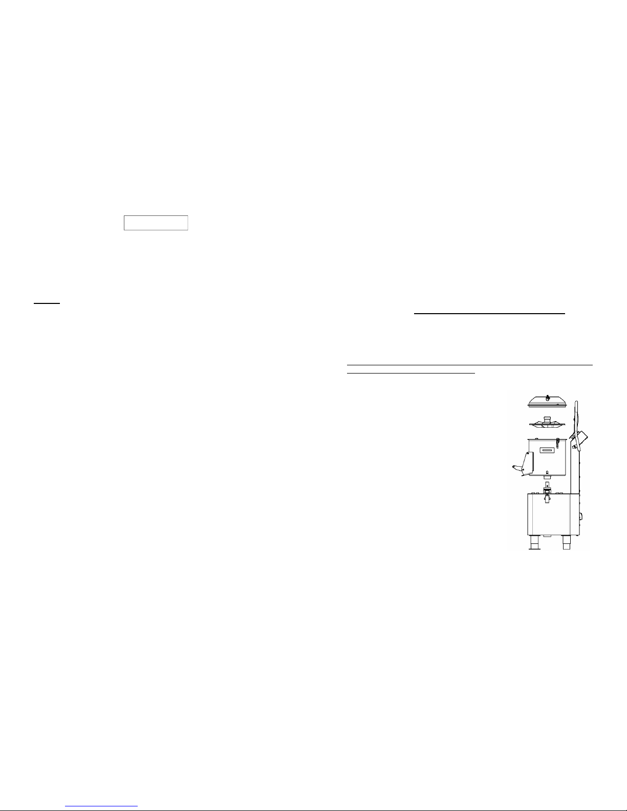
FIG. n°12 –Dismantled machine
Page 3
14
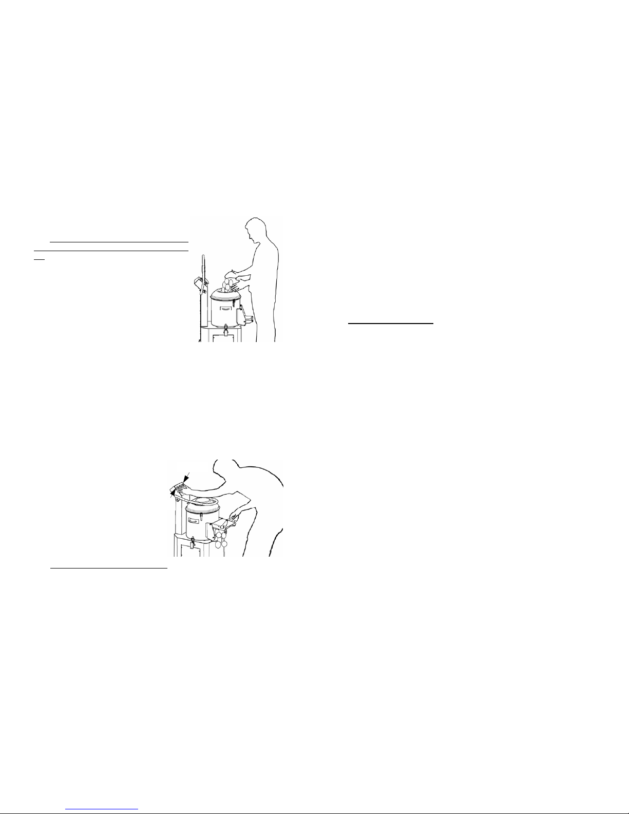
AND WORKING THE PRODUCT (see FIG.
n°10)
NB: The goods to be worked ar e loaded gradually
on the cap from the upper cover when the motor is
off.
Adhere to the following procedure:
1 load the product from the upper cover, making
sure that the discharge door is closed well;
2 check that the machine is not too full and that
the level of the product does not go over the a-
brasive band inside the machine;
3 close the upper cover;
4 open the water flow using the faucet on the
hopper;
Running:
1 set the desired work time with the timer
(max time 5 min.);
2 then start the machine by pressing the START pushbutton;
3 if the cover and/or discharge door are accidentally opened or moved while the
machine is running, the machine will stop; when closed press the START but-
ton;
4 open the water flow using the faucet on the hopper;
5 if the machine is ou tfitted with a stand with sieve, repeatedly unload the slag
tray, to avoid the water dripping.
Unloading the worked product:
(see FIG. n°11)
1 close the water faucet and put a big con-
tainer near the discharge outlet;
2 to unload the material open the dischar-
ge door, keeping it open with your right
hand; press the OUT and START
pushbutton at the same time with
your left hand; the machine will
start unloading the product by centrifu-
gal force;
3 once the unloading is complete the ma-
chine will stop by releasing the pu-
shbuttons and the discharge door;
N.B.: Avoid making an empty machine turn.
FIG. n°10 - Loading the product
FIG. n°11 -Unloading the product
START
OUT
3
CHAP. 7 - MAINTENANCE page 16
7.1 - GENERALITIES
7.2 - BELT
7.3 - FEET
7.4 - FEEDING CABLE
CHAP. 8 - DISMANTLING page 16
8.1 - PUTTING IT OUT OF WORK
8.2 - DISPOSAL
INDEX OF DRAWINGS
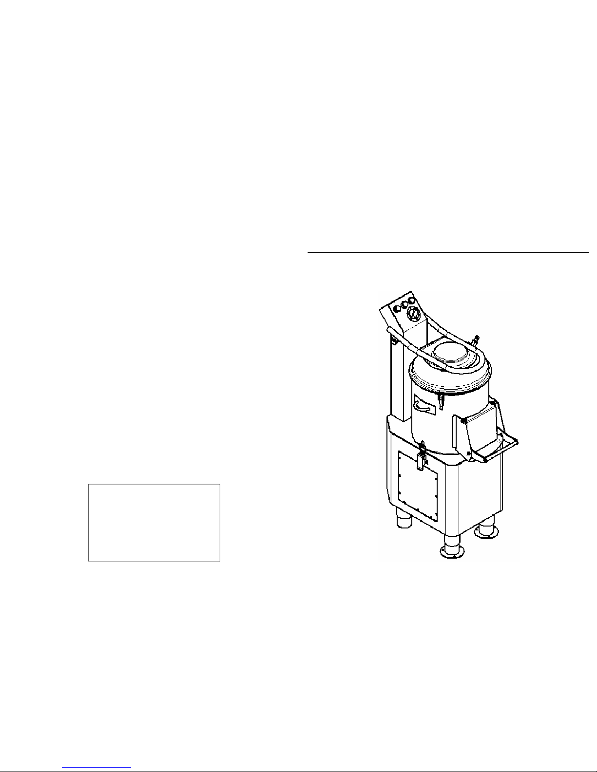
FIG. n°1 - Generale view of the machine pa ge 6
FIG. n°2 - Drawings of dimensions page 6
FIG. n°3 - Package description page 8
FIG. n°4 - Discharge diagram page 9
FIG. n°5 - Serial number—technical plate page 10
FIG. n°6 - Mn electrical diagram page 11
FIG. n°7 - Tf electrical diagram page 12
FIG. n°8 - Cap rotation page 13
FIG. n°9 - Position of controls page 13
FIG. n°10 - Loading the product page 14
FIG. n°11 - Unloading the product page 14
FIG. n°12 - Dismantled machine page 15
Page 4

4
CHAP. 1 - MACHINE INFORMATION
1.1 - GENERAL PRECAUTIONS
• The machine must only be used by trained personnel who are perfectly aware
of the safety norms contained in this manual.
• If there is a turnover of staff, promptly provide proper training for new
personnel.
• Even if safety devices are installed on the machine do not place hands near
moving parts and avoid touching the machine with wet or damp hands.
• Before carrying out any type of maintenance or cleaning, disconnect the
machine plug from the electrical outlet.
• When intervening for mainteannce or cleaning purposes (therefore the
protections are removed) carefully evaluate residual risks .
• During maintenance or cleaning always concentrate on the operations in
progress.
• Regularly check the state of the feeding cable (completely unwinding the
cable, avoiding twisting it, is advisable to avoid potential risks); a worn or
broken cable can present serious danger of the electrical kind; avoid
compressing the wire with weights, leaving it in contact with hot or sharp
surfaces and pulling on it to unplug it from the outlet.
• If the machine shows signs of malfunctioning or does not work, do not use it
or try to repair it; contact the “Assistance Center”, indicated on the back of
this manual.
• The combination of the OUT and START pu shbuttons must only be used for
unloading the worked product.
• The machine must only be used for cleaning potatoes / mussels / onions.
The manufacturer is not responsible in the following cases:
⇒ if the machine is mishandled or the safety devices are installed by
unauthorized personnel;
⇒ if components are replaced with unoriginal
parts;
⇒ if the instructions in this manual are not followed carefully;
⇒ if the machine surfaces are treated with inappropriate products ( inflammable,
corrosive or harmful substances).
1.2 - SAFETY DEVICES INSTALLED ON THE MACHINE
The safety devices against risks of electrical nature conform with the norms EN
60335-1, EN 55014 and the directives 73/23/CEE, 89/336/CEE, while the
mechanical safety devices conform with the directives 98/37 CEE.
The machine is equipped with:
• a starting device consisting of a control card insulated in IP 34, 24 Volts,
which enables:
- turning the machine on and off;
13
4.4 - OPERATIONAL CHECK
Before proceeding to testing make sure the upper cover and the discharge door are
well-blocked, then check the running of the machine with the following
procedure:
1 check that the upper cover and the discharge door are closed well;
2 press the START pushbutton and then the STOP one;
3 repeat the same operation, checking that the cap rotates in a counterclockwise
direction (see FIG. n°8) through the closed transparent upper cover;
4 check if the machine stops when running by opening the cover or discharge
door, and once it is closed if the machine restarts by pushing the START
pushbutton;
5 to discharge the material open the discharge door, keeping it open with your
right hand and at the same time pushing the OUT and START buttons on the
pushbutton strip with your left hand; the machine will start by unloading the
potatoes by centrifugal force (see FIG.n°11).
CHAP. 5 - MACHINE USE
5.1 - CONTROLS
The controls are located on the pushbutton strip above
5.2 - LOADING
FIG. n°8 - Cap rotation
4
3
2
1
1 OUT is the pushbutton for the automatic
discharge of the product; it works only if it is
pressed at the same time as the START
button.
2 STOP is the pushbutton to stop the machine.
3 START is the pushbutton to start the
machine.
4 Timer (max time 5 min.)
FIG. n°9 - Position of controls
Page 5

12
FIG. n°7 - Tf electrical diagram
4.3.2 - Diagram of three-phase electrical system
FEED
TENSION CHANGE
DOOR MICROSWITCH
COVER MICRO
GREEN/BLACK
BLUE/BLACK
RED
WHITE
BLACK
DISCHARGE PUSHBUTTON
ON BUTTON OFF BUTTON
5
- controlling the unloading of the product;
- controlling the safety micros;
• a micro, which causes the machine to stop in case the cover or discharge door
opens (see FIG. n°1), does not allow the machine to turn on if it is not in the
closed position;
• an N.V.R. device in the control circuit which requires the machine to be
restarted if there is an accidental lack of electricity and it enables restarting the
machine only by using the START pushbutton;
Furthermore the machine is equipped with an upper transparent cover which
enables checking the working of the product in progress without any risk s.
1.3 - DESCRIPTION OF THE MACHINE
1.3.1 - General description
The line of CED professional PPJ/LCJs has been designed and manufactured by
our company with the precise objective of guaranteeing:
- maximum safety during use, cleaning and maintenance;
- maximum hygiene, the result of the careful selection of materials which come
into contact with foodstuffs and due to the elimination of sharp edges from the
part which comes into contact with the product, in such a way to guarantee
easy and thorough cleaning;
- all the components are robust and stable;
- maximum silence thanks to the belt transmission.
1.3.2 - Constructive features
Professional I PPJ/LCJ are made of AISI 304 steel.
The discharge door is polished aluminum; the adjustable feet are stainless steel;
the cover is a plastic material, while the hopper is made of AISI 304 steel, the
work plate is aluminum with the disk made of AISI 304 steel; the internal walls of
the container are in abrasive resin to enable a higher level of abrasion with the
product to be worked.
Page 6

6
KEY:
1. Pushbutton strip
2. Hopper
3. Cover block hinge
4. Pan
5. Pan block hinge
6. Maintenance door
7. Feet
8. Flanged feet
9. Structure
10. Discharge door
11. Cover
12. Feeding tap
13. Handle
14. Stand
15. Sieve
NB: there is the possibility of adding the sieve to the stan d
to collect waste.
CHAP. 2 - TECHNICAL DATA
2.1 - DIMENSIONS, WEIGHT, CHARACTERISTICS ...
1.3.3 - Machine makeup
14
15
3
1
2
5
7
9
4
8
10
12
13
6
11
11
4.3 - ELECTRICAL DIAGRAMS
4.3.1 - Diagram of the single-phase electrical system
FIG. n°6 - Mn electrical diagram
FEED
TENSION CHANGE
DOOR MICROSWITCH
COVER MICRO
DISCHARGE PUSHBUTTON
GREEN/BLACK
BLUE/BLAK
RED
WHITE
BLACK
ON BUTTON OFF BUTTON
Page 7

10
4.2 - ELECTRICAL CONNECTIONS
4.2.1 - PPJ/LCJ/PCJ with single-phase motor
The machine is outfitted with a feeding cable with a cross section area of 3x1.5
mm
2
, length 1.5m.
Connect the machine to 230V./50Hz by means of a blue CEI plug, interposing a
magnetothermic-differential switch of 10A, ∆ I = 0.03A. At this point make sure
that the grounding system works perfectly.
Furthermore check that the data shown on the serial number-technical plate (FIG.
n°5) correspond to the data on the delivery notes.
4.2.2 - PPJ/LCJ with three-phase motor
The machine is outfitted with a feeding cable with a cross section area of 5 x 1.5
mm²; length ≅ 1.5 m.
Connect the machine to the 400V./50Hz three-phase electrical network by means
of a CEI plug, interposing a magnetothermic-differential switch of 10 A, ∆I =
0.03 A.
At this point make sure that the grounding system works perfectly.
Before finally connecting the machine to the three-phase feeder line, check the
direction of rotation of the cap by pressing the START pushbutton (see FIG. n.°9)
then immediately stop it by pressing the STOP pushbutton.
The direction of rotation of the cap seen from the discharge outlet must be
counterclockwise; if the direction of rotation is not exact, invert two of the three
feeding wires in the plug or outlet (see FIG. n°8).
The three-phase motor can run with a tension of either 230 V.or 400V. If not
otherwise specified the connections are carried out for 400V.; to adapt to a threephase 230V. network ask for assistance from the “ASSISTANCE CENTER”.
which do not bring about its malfunctioning.
FIG. n°5 - Serial number-technical plate
7
TAB. n°1 - MEASUREMENTS AND TECHNICAL FEATURES
ATTENTION: The electrical characteristics the machine is prearranged for are
indicated by a plate (attached to the back); before connecting the machine see 4.2
electrical connection.
Model u.m. PPJ10 PPJ20 LCJ10 LCJ20 PPJ10 2V
- PP/PC
PPJ10 2V
- PP/AV
Power source Mn
Tf
230 V. / 50 Hz
230 - 400 V. / 50 Hz
Length A mm
775 880 775 880 775 775
Length B mm
470 560 470 560 470 470
Height C mm
1310 1500 1310 1500 1.310 1.310
Height D mm
1040 1190 1040 1190 1.040 1.040
Capacity kg
10 20 10 20 10 10
Revolutions r.p.m
- 275 - 150 150/300 310/460
Motor Hp
0.75 1,5 0,75 1,5 0,50/0,90 0,50/0,75
Power watt
550 1.102 550 1.102 368/338 368/552
Net weight
kg
46.5 59 46.5 59 48,5 48,5
Noise level dB
≤70 ≤70 ≤70 ≤70 ≤70 ≤70
400V/50Hz
Page 8

8
CHAP. 3 - RECEIVING THE MACHINE
3.1 - SHIPPING THE MACHINE (see FIG. n°3)
The machine leaves our warehouses correctly packaged, such a package consists
of: a) an external box in robust cardboard and a wooden pallet;
b) the machine;
c) this manual;
d) the CE compliance certificate.
If requested/ordered:
e) stand with sieve.
FIG. n°3 - Package description
b)
e)
a)
c)
d)
9
3.2 - CHECKING THE PACKAGE UPON RECEIPT
When the package is received, if there is no external damage, open the package
and check that all the material is inside (see FIG. n°3).
If the package shows signs of mishandling, bumps or falls upon delivery, the
shipping company must be made aware of the damage within 3 days of the
delivery date indicated on the documents, and a detailed report must be written on
the damage to the machine. Do not overturn the package!! When the package is
being moved make sure that it is firmly held in the four fundamental points
(keeping it parallel to the floor).
3.3 - DISPOSING OF THE PACKAGE
The package components (cardboard, pallets, plastic and polyurethan foam strap)
are produced like solid urban waste, therefore they can easily be disposed of.
If the machine is installed in countries with particular norms, dispose of the
packages according to the laws in force.
CHAP. 4 - INSTALLATION
4.1 - MACHINE PLACEMENT
When choosing the plane the machine will be placed on the dimensions shown in
Tab. 1 must be considered (based on the model), therefore the surfaces must be
wide enough to hold it, and it must be well-levelled and dry.
Prearrange a discharge tube (ø60 mm.) under the machine and a drain trap on the
floor, or a floor grate to collect
the water or other waste
material.
Furthermore the machine must
be placed as near as possible to
a faucet (ø12 mm.), which
enables the feeding tube to be
easily and safely attached (see
FIG. n°4).
Once the machine is placed
proceed to blocking it by
fastening it to the floor with the
setscrews on the flanged feet
(see FIG.). Furthermore the
machine must be placed in an
environment with a maximum
humidity of 75%, which is not
salty and has a temperature
between +5°C and +25°C; in
any case in environments
Fig. n°4 - Discharge diagram
Load ø12
PPJ/LCJ/PCJ10
h.910 mm.
Discharge
120
 Loading...