

Page 1
1 February 2011 / Change 4
Aircraft Serial No: ________
Author: Ing. M. Zahálka, TL-Ultralight, s.r.o.
This Pilot Operating Handbook must remain in the aircraft and be accessible to the pilot all times.
Page 2

(THIS PAGE BLANK)
Page 3

Pilot Operating Handbook Section 0
TL3000 Sirius Introduction
Dear Sirius Owner:
Congratulations on the purchase of your TL-3000 Sirius which is the result
of many years of development by our company. We strive to be the leading
designer of quality aircraft worldwide. You will find your new Sirius aircraft very
enjoyable, extremely economical, and easy to maintain.
The Sirius is the ideal Light Sport Airplane. It is fast, economical, pleasing to the
eye, and user friendly. We at TL Aircraft are certain that your Sirius will give you
hours and hours of leisure flying and enjoyment. With this Pilot Operating
Handbook (POH), we hope to help inform you about the design and operation of
your aircraft.
This Pilot Operating Handbook is to be used as a guide to assist the pilot to safely
use the Sirius aircraft. The contents are not intended to be a final authority and
although proofed extensively they are still not considered error free. Therefore, the
pilot in command is the final authority for the safe operation of the aircraft. Should
there be any questions or errors found in reading this handbook please contact us
immediately and we will issue a clarification.
I believe that your airplane will be very satisfying and provide you with years of
pure enjoyment. Please study and become familiar with this POH manual and the
respective manuals for the propeller and rescue system.
Thank you again for your business. We look forward to a continuing satisfied
customer relationship. Feel free to contact us if you have any questions or
comments regarding your Sirius aircraft.
I wish you a lot of joy flying your new TL-3000 Sirius.
In Hradec Králové 1st January 2010.
TL Ultralight L.T.D.
(sig)
Jiri Tlusty
1 Feb 11 – Chg 4 i
Copyright © 2011 Reproduction of this document or any of its parts is forbidden
Page 4

Pilot Operating Handbook Section 0
TL3000 Sirius Introduction
Notice! The information contained in this document is for reference and information only.
The pilot is the final and only responsible party for the safe operation of this aircraft.
TL-ULTRALIGHT s.r.o.
Airport, building 84
503 41 Hradec Kralove
tel/fax 495213378
tel 495.218.910.521.1753
info@tl-ultralight.cz
www.tl-ultralight.cz
1 Feb 11 – Chg 4 ii
Copyright © 2011 Reproduction of this document or any of its parts is forbidden
Page 5

Pilot Operating Handbook Section 0
TL3000 Sirius Introduction
Notice! The information contained in this document is for reference and information only.
The pilot is the final and only responsible party for the safe operation of this aircraft.
SECTION INDEX
GENERAL INFORMATION .............................................. 1
OPERATING LIMITATIONS ............................................ 2
EMERGENCY PROCEDURES ........................................ 3
NORMAL PROCEDURES ............................................... 4
PERFORMANCE ............................................................. 5
WEIGHT & BALANCE INFORMATION ........................... 6
AIRPLANE and SYSTEMS DESCRIPTION ..................... 7
REQUIRED PLACARDS & MARKINGS .......................... 8
AIRCRAFT HANDLING, SERVICE & MAINTENANCE ... 9
SUPPLEMENTARY INFORMATION & APPENDIX A ..... 10
1 Feb 11 – Chg 4 iii
Copyright © 2011 Reproduction of this document or any of its parts is forbidden
Page 6

Pilot Operating Handbook Section 0
NOTE
CAUTION
WARNING
TL3000 Sirius Introduction
Notice! The information contained in this document is for reference and information only.
The pilot is the final and only responsible party for the safe operation of this aircraft.
NOTES, CAUTIONS, AND WARNINGS
Throughout this manual, small boxes are inserted referencing a Note, Caution,
or Warning. These are items which require particularly close attention for
special conditions or procedures.
This text box emphasizes specific operating conditions, steps in a
procedure, helpful hints or useful advice.
This text box represents danger to equipment or operation. By not
observing the cautions, the result could be the destruction of
equipment and possibly personal danger and injury.
This text box represents a hazardous situation. Warnings are
used to call attention to operating procedures or conditions
which, if not strictly observed, may result in personal injury or
death.
Every owner, pilot, operator, or user of the Sirius should become familiar with the
entire contents of this Pilot Operating Handbook (POH). The text consists of
flight and maintenance information combined with training instruction, Section 10,
in accordance with ASTM 2245 and is required to be on board the plane and
available to the pilot during all flights. It also incorporates only partial information
about related systems from Rotax®, the engine manufacturer, Woodcomp® or
DUC® ,the propeller suppliers, and Galaxy
system. Please refer to the latest edition of those manufacturer manuals for
specific and complete detailed operation of each aircraft system.
®,
the installed aircraft parachute
1 Feb 11 – Chg 4 iv
Copyright © 2011 Reproduction of this document or any of its parts is forbidden
Page 7

Pilot Operating Handbook Section 0
CAUTION
TL3000 Sirius Introduction
Notice! The information contained in this document is for reference and information only.
The pilot is the final and only responsible party for the safe operation of this aircraft.
This flight and operational manual produced by TL Ultralight is designed to
introduce TL -3000 SIRIUS aircraft to its operator. It provides the basic usage
information and operational procedures ensuring the most effective aircraft
utilization by the operator.
Each holder of this flight and operational manual and/or its parts is obliged to
maintain it in updated state by implementation of amendments, revisions
and changes as published in the bulletin through the following web-page:
http:/sirius.aero/owners/downloads
Owners are encouraged to keep their address and contact information
current in order to receive the latest continued airworthiness program
information. See the contact information below to email, fax, call or mail
your contact data so that you can be informed and kept current on the safe
operation of your aircraft.
This flight and operational manual is divided by topics into several sections
that are split into paragraphs according to the significance and importance of
their subject matter. Page replacement, amendment or handwriting revision,
must all be recorded on the ‗List of Changes‘ log page by recording the
change or amendment serial number, number of the published change or
page changed or amended, new page or change publishing date, and
implementation date and signature.
This operational manual is established in such a way that any revision or
amendment execution is only possible by replacing or adding the
appropriate pages and discarding the obsolete pages. Therefore, it is
necessary that all manual holders pay increased attention to recording all
changes and amendments and their implementing instructions.
1 Feb 11 – Chg 4 v
Copyright © 2011 Reproduction of this document or any of its parts is forbidden
The Sirius meets the standard specification Design and Performance
(D&P) established by ASTM International, Inc, (ASTM) Document F
2245, and it is therefore restricted by that guideline. The aircraft does
not comply with any FAA Part 22, or 23 certification processes.
Compliance with regulations placed upon the airplane category
should be strictly adhered to by the pilot in command (PIC)
Page 8

Pilot Operating Handbook Section 0
CAUTION
NOTE
TL3000 Sirius Introduction
Notice! The information contained in this document is for reference and information only.
The pilot is the final and only responsible party for the safe operation of this aircraft.
The items discussed in each of the amplified procedures are
intended to comply with ASTM airplane Flight Training Supplement
(FTS) in lieu of a separate manual. Additional flight training
information is available in Section 10 of this manual. None of these
items or procedures is intended to replace properly qualified ground
or in-flight instruction by an FAA certified flight instructor (CFI).
This POH manual is valid only if the PIC complies with any changes
that may be issued at a later date. Any pages affected by a change
should be removed and replaced with the current effective pages
immediately.
The aircraft manufacturer issues notices of information and mandatory
bulletins to ensure continued airworthiness in accordance with ASTM
2295 for the TL-3000 Sirius Special Light Sport Aircraft (SLSA). The
notices are provided to all known owners of the Sirius aircraft.
All bulletins may be downloaded from:
http://www.sirius.aero/owners/downloads
To receive updates and bulletins on the safe continued operation of
your aircraft please contact us at the address below. If this manual
is found not to be current, revisions missing, or pages removed
contact our USA location in accordance with the ASTM / TL
Continued Airworthiness Service program for replacements.
TL Ultralight, s.r.o.
Continued Airworthiness Service
8222 Remount Road
KORK Municipal Airport
North Little Rock, AR 72118
Info1@sportair.aero
www.sirius.aero
Phone: 501.228.7777
Fax: 501.227.8888
1 Feb 11 – Chg 4 vi
Copyright © 2011 Reproduction of this document or any of its parts is forbidden
Page 9

Pilot Operating Handbook Section 0
TL3000 Sirius Introduction
Notice! The information contained in this document is for reference and information only.
The pilot is the final and only responsible party for the safe operation of this aircraft.
LIST OF EFFECTIVE PAGES
Page ...................... Date
Cover .............. 02-01-11
i ....................... 02-01-11
ii ...................... 02-01-11
iii ..................... 02-01-11
iv ..................... 02-01-11
v ...................... 02-01-11
vi ..................... 02-01-11
vii .................... 02-01-11
viii .................... 02-01-11
1-1 ................... 02-01-11
1-2(blank) ........ 02-01-11
1-3 ................... 02-01-11
1-4 ................... 02-01-11
1-5 ................... 09-31-10
1-6 ................... 02-01-11
1-7 ................... 02-01-11
1-8 ................... 02-01-11
1-9 ................... 02-01-11
1-10 ................. 02-01-11
1-11 ................. 02-01-11
1-12 ................. 02-01-11
1-13 ................. 02-01-11
1-14 ................. 02-01-11
1-15 ................. 02-01-11
1-16 ................. 02-01-11
1-17 ................. 02-01-11
1-18 ................. 02-01-11
1-19 ................. 02-01-11
1-20 ................. 02-01-11
2-1 ................... 02-01-11
2-2 (blank) ....... 02-01-11
2-3 ................... 02-01-11
2-4 ................... 02-01-11
2-5 ................... 02-01-11
2-6 ................... 02-01-11
2-7 ................... 02-01-11
2-8 ................... 02-01-11
2-9 ................... 02-01-11
2-10 ................. 02-01-11
2-11 ................. 02-01-11
2-12 ................. 02-01-11
3-1 ................... 02-01-11
3-2 (blank) ....... 02-01-11
3-3 ................... 02-01-11
3-4 ................... 02-01-11
3-5 ................... 02-01-11
3-6 ................... 02-01-11
3-7 ................... 02-01-11
3-8 ................... 02-01-11
3-9 ................... 02-01-11
3-10 ................. 02-01-11
3-11 ................. 02-01-11
3-12 ................. 02-01-11
Page ...................... Date
3-13 ................. 02-01-11
3-14 ................. 02-01-11
3-15 ................. 02-01-11
3-16 ................. 02-01-11
3-17 ................. 02-01-11
3-18 ................. 02-01-11
3-19 ................. 02-01-11
3-20 ................. 02-01-11
3-21 ................. 02-01-11
3-22 ................. 02-01-11
4-1 ................... 02-01-11
4-2 (blank) ....... 02-01-11
4-3 ................... 02-01-11
4-4 ................... 02-01-11
4-5 ................... 02-01-11
4-6 ................... 02-01-11
4-7 ................... 02-01-11
4-8 ................... 02-01-11
4-9 ................... 02-01-11
4-10 ................. 02-01-11
4-11 ................. 02-01-11
4-12 ................. 02-01-11
4-13 ................. 02-01-11
4-14 ................. 02-01-11
4-15 ................. 02-01-11
4-16 ................. 02-01-11
4-17 ................. 02-01-11
4-18 ................. 02-01-11
4-19 ................. 02-01-11
4-20 ................. 02-01-11
4-21 ................. 02-01-11
4-22 ................. 02-01-11
4-23 ................. 02-01-11
4-24 ................. 02-01-11
4-25 ................. 02-01-11
4-26 ................. 02-01-11
4-27 ................ 02-01-11
4-28 ................. 02-01-11
4-29 ................ 02-01-11
4-30 (blank) ..... 02-01-11
5-1 ................... 02-01-11
5-2 (blank) ....... 02-01-11
5-3 ................... 02-01-11
5-4 ................... 02-01-11
5-5 ................... 02-01-11
5-6 ................... 02-01-11
5-7 ................... 02-01-11
5-8 ................... 02-01-11
5-9 ................... 02-01-11
5-10 ................. 02-01-11
5-11 ................. 02-01-11
5-12 (blank) ..... 02-01-11
6-1 ................... 02-01-11
Page .................... Date
6-2 (blank) ....... 02-01-11
6-3 ................... 02-01-11
6-4 ................... 02-01-11
6-5 ................... 02-01-11
6-6 ................... 02-01-11
6-7 ................... 02-01-11
6-8 ................... 02-01-11
6-9 ................... 02-01-11
6-10 ................. 02-01-11
6-11 ................. 02-01-11
6-12 ................. 02-01-11
6-13 ................. 02-01-11
6-14 ................. 02-01-11
6-15 ................. 02-01-11
6-16 ................. 02-01-11
7-1 ................... 02-01-11
7-2 (blank) ....... 02-01-11
7-3 ................... 02-01-11
7-4 ................... 02-01-11
7-5 ................... 02-01-11
7-6 ................... 02-01-11
7-7 ................... 02-01-11
7-8 ................... 02-01-11
7-9 ................... 02-01-11
7-10 ................. 02-01-11
7-11 ................. 02-01-11
7-12 ................. 02-01-11
7-13 ................. 02-01-11
7-14 ................. 02-01-11
7-15 ................. 02-01-11
7-16 ................. 02-01-11
7-17 ................. 02-01-11
7-18 ................. 02-01-11
7-19 ................. 02-01-11
7-20 ................. 02-01-11
8-1 ................... 02-01-11
8-2 (blank) ....... 02-01-11
8-3 ................... 02-01-11
8-4 ................... 02-01-11
8-5 ................... 02-01-11
8-6 ................... 02-01-11
8-7 ................... 02-01-11
8-8 ................... 02-01-11
8-9 ................... 02-01-11
8-10 ................. 02-01-11
9-1 ................... 02-01-11
9-2 (blank) ....... 02-01-11
9-3 ................... 02-01-11
9-4 ................... 02-01-11
9-5 ................... 02-01-11
9-6 ................... 02-01-11
9-7 ................... 02-01-11
1 Feb 11 – Chg 4 vii
Copyright © 2011 Reproduction of this document or any of its parts is forbidden
Page 10

Pilot Operating Handbook Section 0
Nr.
Date
Revised
Pages
Type of Revision
Posted
By
0
1 May 2009
None
Original Issue
N/A
1
31 Mar 2010
All
Re-issue
N/A
2
31 Aug 2010
All
Re-issue
N/A
3
31 Oct 2010
All
Re-issue
N/A
4
1 Feb 2011
All
Re-issue
TL3000 Sirius Introduction
Notice! The information contained in this document is for reference and information only.
The pilot is the final and only responsible party for the safe operation of this aircraft.
Page ...................... Date
9-8 ................... 02-01-11
9-9 ................... 02-01-11
9-10 ................. 02-01-11
9-11 ................. 02-01-11
9-12 ................. 02-01-11
9-13 ................. 02-01-11
9-14 ................. 02-01-11
9-15 ................. 02-01-11
9-16 ................. 02-01-11
9-17 ................. 02-01-11
9-18 ................. 02-01-11
9-19 ................. 02-01-11
9-20 ................. 02-01-11
9-21 ................. 02-01-11
9-22 ................. 02-01-11
9-23 ................. 02-01-11
9-24 ................. 02-01-11
9-25 ................. 02-01-11
9-26 ................. 02-01-11
9-27 ................. 02-01-11
Page ...................... Date
9-28 ................. 02-01-11
9-29 ................. 02-01-11
9-30 ................. 02-01-11
9-31 ................. 02-01-11
9-32 ................. 02-01-11
9-33 ................. 02-01-11
9-34 ................. 02-01-11
10-1 ................. 02-01-11
10-2 (blank) ..... 02-01-11
10-3 ................. 02-01-11
10-4 ................. 02-01-11
10-5 ................. 09-31-10
10-6 ................. 02-01-11
10-7 ................. 02-01-11
10-8 ................. 02-01-11
10-9 ................. 02-01-11
10-10 ............... 02-01-11
10-11 ............... 02-01-11
10-12 (blank) ... 02-01-11
Page ............... Date
APPENDIX A
10-13 ............... 02-01-11
10-14 ............... 02-01-11
10-15 ............... 02-01-11
10-16 ............... 02-01-11
10-17 ............... 02-01-11
10-18 ............... 02-01-11
10-19 ............... 02-01-
10-20 ............... 02-01-11
10-21 ............... 02-01-11
10-22 ............... 02-01-11
10-23 ............... 02-01-11
10-24 .............. 02-01-11
List of changes
1 Feb 11 – Chg 4 viii
Copyright © 2011 Reproduction of this document or any of its parts is forbidden
Page 11

Pilot Operating Handbook Section 1
TL3000 Sirius General Information
Notice! The information contained in this document is for reference and information only.
The pilot is the final and only responsible authority for the safe operation of this aircraft.
SECTION 1
GENERAL INFORMATION
TABLE OF CONTENTS PAGE
INTRODUCTION ............................................................................................... 1-3
AIRCRAFT ......................................................................................................... 1-4
3D TRANSPARENT DRAWING ........................................................................ 1-3
TOP VIEW DRAWING ....................................................................................... 1-5
SIDE VIEW DRAWING ...................................................................................... 1-6
FRONT / REAR VIEW DRAWING ..................................................................... 1-5
BASIC DIMENSIONS ........................................................................................ 1-7
AIRPLANE WEIGHTS ....................................................................................... 1-8
CABIN / ENTRY DIMENSIONS ......................................................................... 1-8
BAGGAGE SPACE AND ENTRY DIMENSIONS .............................................. 1-8
PROPELLEORS ................................................................................................ 1-8
ENGINE ............................................................................................................. 1-8
PARACHUTE SYSTEM ..................................................................................... 1-9
FUEL .................................................................................................................. 1-9
OIL ................................................................................................................... 1-10
BAGGAGE ....................................................................................................... 1-10
SYMBOLS, ABBREVIATIONS, AND TERMINOLOGY .................................... 1-11
GENERAL AIRSPEED TERMINOLOGY ......................................................... 1-11
METEOROLOGICAL TERMINOLOGY ............................................................ 1-12
AIRPLANE PERFORMANCE AND WEIGHT TERMINOLOGY ....................... 1-12
ABBREVIATIONS ............................................................................................ 1-16
V SPEED DEFINITIONS .................................................................................. 1-20
1 Feb 11 – Ch 4 1-1
Copyright © 2011 Reproduction of this document or any of its parts is forbidden.
Page 12

Pilot Operating Handbook Section 1
TL3000 Sirius General Information
Notice! The information contained in this document is for reference and information only.
The pilot is the final and only responsible authority for the safe operation of this aircraft.
(THIS PAGE BLANK)
1 Feb 11 – Ch 4 1-2
Copyright © 2011 Reproduction of this document or any of its parts is forbidden.
Page 13

Pilot Operating Handbook Section 1
TL3000 Sirius General Information
Notice! The information contained in this document is for reference and information only.
The pilot is the final and only responsible authority for the safe operation of this aircraft.
INTRODUCTION
This manual is organized to conform to the ASTM F2746 Standard Specification for
Pilot‘s Operating Handbook (POH). A copy of this POH is issued with each
aircraft and must remain in the aircraft and available to the pilot during flight.
All pilots of this aircraft must read and understand the operation and limitations of
this aircraft design. As such, many items are added as narrative information to
assist them in clearly understanding what is required and in most cases help in
achieving the necessary performance. The POH does not intend to and cannot
replace properly qualified ground or in-flight instruction by an FAA certified flight
instructor. (CFI)
Maintenance and operation of major components, engine, and aircraft parachute
system, propeller, avionics or other installed equipment is provided in the
appropriate manufacturer manuals which are included with the aircraft. The
appropriate manufacturer‘s manual takes precedence over any conflict in this POH.
The Sirius has a high cruising speed and may traverse very different weather
conditions during a single flight. The pilot is responsible for the safe flight of the
aircraft and should be prepared to avoid any meteorological conditions which will
endanger the occupants, the aircraft or both.
Section 1 provides general information and descriptive figures relevant to the aircraft
and the engine. It also contains certain definitions of aeronautical terms, ASTM
Design and Performance standards and commonly used abbreviations.
1 Feb 11 – Ch 4 1-3
Copyright © 2011 Reproduction of this document or any of its parts is forbidden.
Page 14

Pilot Operating Handbook Section 1
TL3000 Sirius General Information
Notice! The information contained in this document is for reference and information only.
The pilot is the final and only responsible authority for the safe operation of this aircraft.
AIRCRAFT
The TL3000 Sirius is a full three axis, high wing, two place, side-by-side seating, tricycle
landing gear aircraft with a toe brake steerable nose wheel. The primary aircraft structure
is carbon fiber and fiberglass UV resistant reinforced laminate with an inner foam core
creating a ‗sandwich‘ layered construction between each ply.
Various options may also be installed; therefore your aircraft may vary from the
descriptions in this manual. Please check with the TL Continuing Airworthiness Center if
you have any specific questions not addressed here.
Front View
Fig. 1-1
1 Feb 11 – Ch 4 1-4
Copyright © 2011 Reproduction of this document or any of its parts is forbidden.
Page 15

Pilot Operating Handbook Section 1
TL3000 Sirius General Information
Notice! The information contained in this document is for reference and information only.
The pilot is the final and only responsible authority for the safe operation of this aircraft.
Side View & Top View
Fig. 1-2
1 Feb 11 – Ch 4 1-5
Copyright © 2011 Reproduction of this document or any of its parts is forbidden.
Page 16

Pilot Operating Handbook Section 1
TL3000 Sirius General Information
Notice! The information contained in this document is for reference and information only.
The pilot is the final and only responsible authority for the safe operation of this aircraft.
3D View
Fig. 1-3
1 Feb 11 – Ch 4 1-6
Copyright © 2011 Reproduction of this document or any of its parts is forbidden.
Page 17

Pilot Operating Handbook Section 1
TL3000 Sirius General Information
Notice! The information contained in this document is for reference and information only.
The pilot is the final and only responsible authority for the safe operation of this aircraft.
BASIC DIMENSIONS
Length .......................................................................... 22.15 ft.
Height .......................................................................... 7.38 ft. (at tail)
Cabin width .................................................................. 45 in.
Nose to Main wheel base……………………………… .. 5.02 ft.
Main wheel spacing…………………………… .............. 7.12 ft.
Wings
Area ............................................................................. 121.23 ft
2,
Span……………………………….................................. 30.84 ft.
Aspect Ratio……………………………………………… 7.92
Root Chord……………………………………………… .. 4.27 ft.
Tip Chord………………………………………………… . 2.95 ft.
Loading…………………………………………………… . 10.89 lb/sf.
Ailerons
Area ............................................................................. 10.98 ft2
Span…………………………………………………… ..... 12.28 ft.
Deflection up…………………………………………… ... 11.50 deg.
Deflection down………………………………………… .. 7.60 deg.
Flaps
Area ............................................................................. 14.22 ft
2
Span……………………………………………… ............ 13.60 ft.
Deflection takeoff……………………………………… .... 10.00 deg.
Deflection half…………………………………………… . 28.00 deg.
Deflection landing……………………………………… ... 45.00 deg.
Elevators
Area….………………………………………………… ..... 21.64 ft2
Span……………………………………………………… . 9.84 ft.
Deflection up………………………………………… ....... 16.70 deg.
Deflection down……………………………………… ...... 8.50 deg.
Rudder
Area…………………………………………………… ...... 12.81 ft2
Deflection left-right…………………………………… ..... 20-20 deg.
General
Glide ratio .................................................................... 13:1
Tire pressure…………………………………………… ... 30 psi
Brakes, left-right-park………………………………… .... Hydraulic disk, DOT 3 or 4
1 Feb 11 – Ch 4 1-7
Copyright © 2011 Reproduction of this document or any of its parts is forbidden.
Page 18

Pilot Operating Handbook Section 1
TL3000 Sirius General Information
Notice! The information contained in this document is for reference and information only.
The pilot is the final and only responsible authority for the safe operation of this aircraft.
AIRPLANE WEIGHTS
Maximum Ramp Weight: 1326 Lbs
Standard Empty Weight: 760 Lbs
Maximum Useful Load: 540 Lbs
Maximum Takeoff or Landing Weight: 1320 Lbs (1430 seaplane)
Maximum Baggage Weight: 75 Lbs. (see limitations)
Maximum Calculated Structural Weight: 1320/1430 Lbs
CABIN / ENTRY DIMENSIONS
Door width: 37―
Door height: 30‖
Head room (from seat bottom to ceiling): 38.5‖
Leg room (from seat back to rudder pedals): 49.5‖
Cabin width: 45‖
Seat width: 19-22‖
Note: Cabin doors are trapezoid not rectangles and are measured at entry.
BAGGAGE SPACE AND ENTRY DIMENSIONS
Maximum Compartment Width: 41‖
Maximum Compartment Height: 32‖
Maximum Compartment Length: 20.5‖
Minimum Compartment Width: 36‖
Minimum Compartment Height: 21.5‖
Entry Width: 37.5‖
Entry Height: 18‖
Note: Baggage area narrows aft from a cube shape to above sizes. Aft baggage shelf is
sloped, and not included in the above area or dimensions.
PROPELLER
Propeller Manufacturer: Woodcomp®, DUC, Sensenich.
(See Master Equipment List (MEL) latest date)
Number of Blades: 2/3
Propeller Type: Fixed-pitch, ground-adjustable
ENGINE
Number of Engines: 1
Engine Manufacturer: Rotax® G.m.b.H. Aircraft Engines
Engine Model Number: 900 Series, Standard Equipment
(See Master Equipment List (MEL) latest date)
Engine Type: Normally-aspirated, liquid/air-cooled, dry sump, gear-reduced
drive, dual carburetor-equipped, four-cylinder, four-stroke,
electronic dual ignition, horizontally-opposed engine.
1 Feb 11 – Ch 4 1-8
Copyright © 2011 Reproduction of this document or any of its parts is forbidden.
Page 19

Pilot Operating Handbook Section 1
NOTE
TL3000 Sirius General Information
Notice! The information contained in this document is for reference and information only.
The pilot is the final and only responsible authority for the safe operation of this aircraft.
GALAXY ROCKET PARACHUTE SYSTEM (GRS)
The rocket deployed aircraft parachute system is standard equipment. It is activated
inside the cockpit by pulling a red ―T‖ handle located on the lower right pilot side position.
The system is secured by a brass safety pin attached to an embroidered red safety tag.
Refer to the Galaxy operational manual included with the aircraft for detailed information.
FUEL
The use of Premium Grade automobile fuel is approved for Rotax 900 series
engines. See the Rotax Operator‘s manual section 10 for more data.
An Antiknock Index (AKI) is the usual octane rating for the US. Rotax specifies a
minimum AKI of 91 for the 912ULS engine. AKI is an average of the RON and the
MON rating method where: AKI = (RON+MON) / 2.
RON is common in Europe and sometimes causes confusion for owners who
operate European engines. 91 RON is approximately 87 AKI (US Regular auto fuel)
and 95 RON is approximately 91 AK (US Premium auto fuel).
Rotax Service Instruction SI-912-016 (or revised latest revised edition) details all
specifications for Rotax engine fluids. A current copy is available at the
airworthiness center web site:
www.sirius.aero/owners/downloads.
Approved Fuel Grade:
91 AKI Unleaded Automobile Fuel, ―Auto gas‖ (Amber color).
Approved Alternate Fuel Grade:
100LL Aviation Fuel, ―Avgas‖ (Blue color).
Total Fuel Capacity:
34.2 US Gallons, in two wing tanks.
Total Unusable Fuel:
2 US Gallons, total fuel system
100LL Avgas is an acceptable alternate fuel if 91 octane unleaded
auto fuel is not available. Due to the high lead content, the use of
100LL Avgas should be less than 30% of engine time without
increased engine maintenance. See the latest Rotax engine
operational supplement for more detailed fuel specifications and
information.
1 Feb 11 – Ch 4 1-9
Copyright © 2011 Reproduction of this document or any of its parts is forbidden.
Page 20
Pilot Operating Handbook Section 1
NOTE
CAUTION
TL3000 Sirius General Information
Notice! The information contained in this document is for reference and information only.
The pilot is the final and only responsible authority for the safe operation of this aircraft.
Total unusable fuel is the minimum amount of fuel an aircraft may
have in its gas tanks before engine fuel starvation. Unusable fuel, as
its name implies, cannot be consumed by the engine for power and
thus cannot be relied upon for flight, but is included in the aircraft
empty weight.
During refueling of the wing tanks, a fuel spill may cause crazing of
the aircraft windows. Flush immediately with clear water but do not rub
the surface to remove the fuel. If the tank is full to the brim it will
eliminate all fuel expansion area. As fuel warms it expands and will
be forced out of the fuel vent line, spill on to the parking area and
cause a fire hazard.
OIL
Oil Capacity: 3.7 Quarts (Empty system)
Oil Filter: Rotax part number 825 701, (or latest Rotax part number).
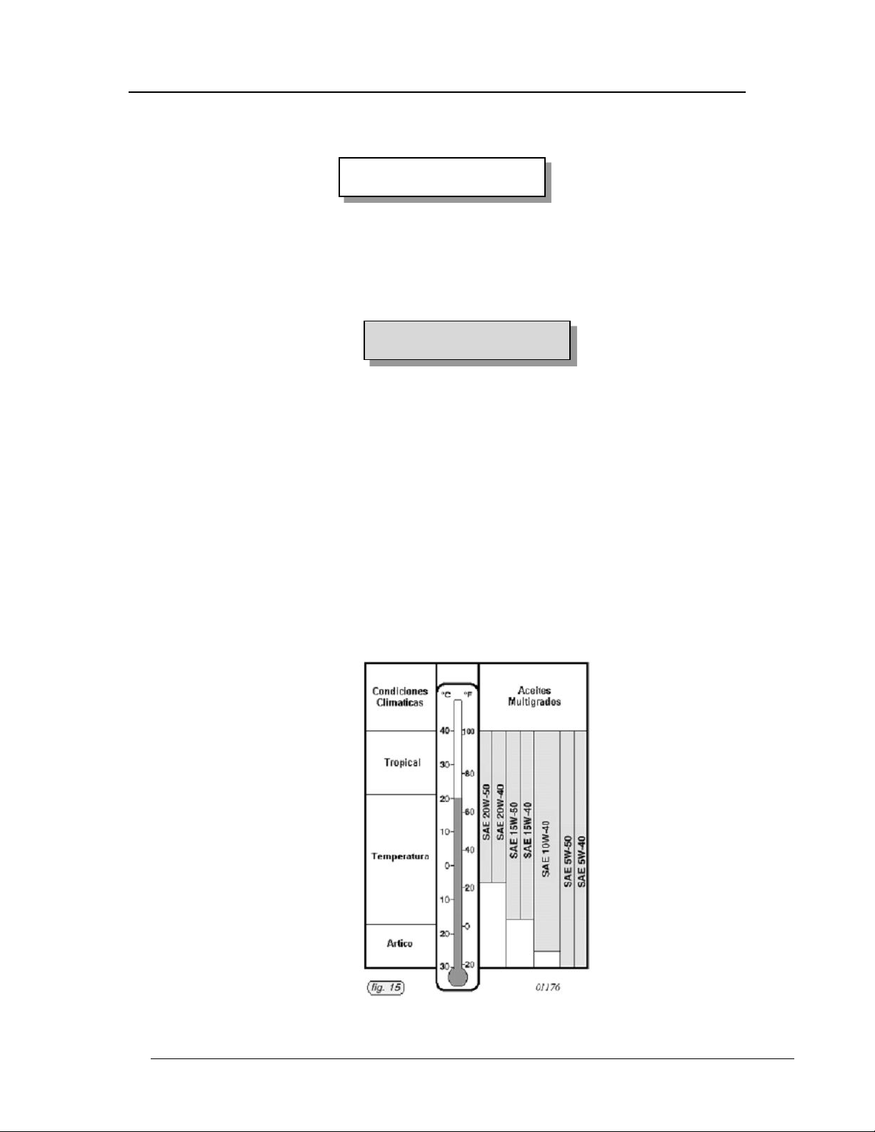
Oil Specifications: Vary depending on the engine operation and may vary from one
aircraft to another depending on the operation, environment and fuel type. Refer to
Figure 1-5 below and the latest Rotax engine oil service, fluid specification and
instructions.
Oil Grade and Temperature Conditions
1 Feb 11 – Ch 4 1-10
Copyright © 2011 Reproduction of this document or any of its parts is forbidden.
Page 21

Pilot Operating Handbook Section 1
CAUTION
TL3000 Sirius General Information
Notice! The information contained in this document is for reference and information only.
The pilot is the final and only responsible authority for the safe operation of this aircraft.
Fig. 1-5
Oil level is checked immediately after engine shutdown for best indication. An oil
change will not require 3.7 quarts as some oil remains in the system for pre oiling and
is not drained. Do not over fill.
No substitutions allowed!
Normal Rotax 900 series engine oil pressure may force the
oil to bypass the filter of non-OEM filters. Rotax Oil Filter:
part number 825 701, or latest version must be used,
BAGGAGE
Baggage is stored behind the seats .The baggage compartment can hold
a maximum of 75 Lbs and is further limited by the maximum aft CG and
structural loading for the aircraft. No concentrated loads are allowed. A
weight and balance calculation should be completed by the PIC prior to
each flight.
SYMBOLS, ABBREVIATIONS, AND TERMINOLOGY
GENERAL AIRSPEED TERMINOLOGY
Best Angle-of-Climb Speed (VX): The speed which results in the greatest gain of
altitude in a given horizontal distance.
Best Rate-of-Climb Speed (VY): The speed which results in the greatest gain in
altitude in a given time.
Best Glide Speed (VG): The speed that will result in maximum glide distance.
Design Cruise Speed (VC): The optimal cruise speed.
Knots Calibrated Airspeed (KCAS): Indicated airspeed corrected for position and
instrument error and expressed in knots. KCAS is equal to KTAS in standard
conditions at sea level.
Knots Indicated Airspeed (KIAS): The speed shown on the airspeed indicator
and is expressed in knots. (Decreases approximately 2kt/1000‘ of ALT.)
Knots True Airspeed (KTAS): KCAS corrected for non-standard temperature and
pressure and is expressed in knots.
1 Feb 11 – Ch 4 1-11
Copyright © 2011 Reproduction of this document or any of its parts is forbidden.
Page 22

Pilot Operating Handbook Section 1
TL3000 Sirius General Information
Notice! The information contained in this document is for reference and information only.
The pilot is the final and only responsible authority for the safe operation of this aircraft.
Maneuvering Speed (VA): The maximum speed at which you may use abrupt full
control travel without exceeding structural limitations of the aircraft or control
systems.
Maximum Flap Extended Speed (VFE): The highest speed permissible with wing
flaps in a prescribed extended position.
Maximum Structural Cruising Speed (VNO): The speed that should not be
exceeded except in smooth air, and then only with caution.
Maximum Sustained Speed in Level Flight (VH): The highest speed that can be
attained in level flight at sea level under standard conditions while the engine is
operating at the manufacturer designated maximum continuous power setting.
Never Exceed Speed (VNE): The speed limit that may never be exceeded under
any conditions at any time due to structural limitations of the airframe or control
systems.
Stalling Speed (VS): The minimum steady flight speed at which the airplane is
controllable without flaps.
Stalling Speed (VS0): The minimum steady flight speed with power off and full
flaps.
METEOROLOGICAL TERMINOLOGY
Indicated Altitude: The altitude displayed on the altimeter.
Mean Sea Level (MSL): The average level of the ocean‘s surface – the level
halfway between mean high and low tides, used as a standard reference for
expressing altitude.
Outside Air Temperature (OAT): The free air static temperature, expressed in
either degrees Celsius (C) or degrees Fahrenheit (F).
Pressure Altitude: The altitude displayed on the altimeter on a standard day when
the altimeter's barometric scale has been set to 29.92 inches of mercury (1013 mb).
Standard Temperature: 15°C (59°F) at sea level pressure altitude. (Decreases
approximately 2°C (3.5°F) for each 1000 feet increase of altitude.)
True Altitude: The true height above mean sea level (MSL). True altitude is
indicated altitude corrected for nonstandard atmospheric pressure.
1 Feb 11 – Ch 4 1-12
Copyright © 2011 Reproduction of this document or any of its parts is forbidden.
Page 23

Pilot Operating Handbook Section 1
NOTE
TL3000 Sirius General Information
Notice! The information contained in this document is for reference and information only.
The pilot is the final and only responsible authority for the safe operation of this aircraft.
AIRPLANE PERFORMANCE AND WEIGHT TERMINOLOGY
Arm: The horizontal distance expressed in inches from the reference datum plane
to the center of gravity (CG) of an item or location.
Units of measurements and weights must be consistent for each set
of calculations and in the same system of units, i.e., pounds and
inches, or kilograms and centimeters.
Ballast: A specific amount of weight attached in a specific location, which can be
temporarily or permanently installed in an aircraft, to help bring its CG within the
required limits. If temporary ballast must be used for certain operations, the exact
amount and its location must be placarded on the instrument panel within clear view
of the pilot. The use of Ballast increases Empty Weight and reduces Useful Load.
Basic Empty Weight: The standard empty weight plus the weight of any
additionally installed or optional equipment.
Empty Weight Center of Gravity: The CG of an aircraft in its basic empty weight
condition, and is an essential part of the weight and balance record.
Brake Horsepower: The power developed by the engine expressed in
horsepower and measured by an instrument resistant (brake) device.
Center of Gravity (CG): A point along an aircraft‘s longitudinal axis at which all the
loads and forces are perfectly concentrated and balanced. It is computed by
dividing the total moment by the total weight of the airplane. Its distance from the
reference datum is found by dividing the total moment by the total weight of the
airplane.
(Total Moment / Total Weight = Center of Gravity)
Center of Gravity Arm: The arm (distance) from data plane obtained by adding
the airplane's individual moments and dividing the sum by the total weight.
Center of Gravity Limits are the extreme forward and aft CG locations (limits)
within which the airplane must be operated at any given weight.
1 Feb 11 – Ch 4 1-13
Copyright © 2011 Reproduction of this document or any of its parts is forbidden.
Page 24

Pilot Operating Handbook Section 1
TL3000 Sirius General Information
Notice! The information contained in this document is for reference and information only.
The pilot is the final and only responsible authority for the safe operation of this aircraft.
Center of Gravity Range: The horizontal distance, along an aircraft‘s longitudinal
axis, within which an aircraft has been found to be fully maneuverable at all
specified design speeds, weights and loading configurations.
Datum: (datum plane) A convenient vertical reference plane along the longitudinal
axis of an aircraft from which all horizontal measurements are taken, the forward tip
of the propeller spinner is the datum for the Sirius.
Demonstrated Crosswind Velocity: The velocity of the crosswind component at
which adequate control of the airplane was demonstrated during takeoff and
landing tests. The value is not considered to be a maximum limit.
Empty Weight Center of Gravity: The CG of an aircraft in its current empty
weight condition, an essential part of the weight and balance record.
Gallons Per Hour: The amount of fuel (in US gallons) consumed in one hour.
Gear Box: The gears forward of the engine and aft of the propeller used to change
(reduce) the propeller RPM by a factor of 2.43 of the engine RPM.
Installed Equipment: All accessories and equipment permanently installed on an
airframe or engine at the time of weighing included in the ―Installed Equipment List‖
resulting in the Basic aircraft weight. Additions and deletions must be noted in the
list and new Weight and Balance calculations performed to determine the
magnitude and effect of weight change
Manifold Pressure: The atmospheric pressure measured in the engine's induction
system and is expressed in inches of mercury (Hg).
Maximum and Minimum Weights: Due to balance, structural, and aerodynamic
considerations, maximum or minimum weights for certain locations on the aircraft
are specified. For example, the pilot‘s minimum (100Lbs) and maximum (250Lbs)
weight are specified for some CG calculations. The same is true for baggage,
cargo, fuel, and any other disposable or variable load.
Maximum Forward and Maximum Aft CG Locations: A specified forward most
and rear most CG location along the aircraft longitudinal axis. These CG location
limits are expressed in inches from a convenient reference datum, the forward face
of the engine propeller flange.
Maximum Design Weight: The maximum total weight, for which the aircraft‘s
structure has been tested by the manufacturer for normal or seaplane operations.
1 Feb 11 – Ch 4 1-14
Copyright © 2011 Reproduction of this document or any of its parts is forbidden.
Page 25

Pilot Operating Handbook Section 1
TL3000 Sirius General Information
Notice! The information contained in this document is for reference and information only.
The pilot is the final and only responsible authority for the safe operation of this aircraft.
Maximum Gross Weight: The maximum total weight, for which the aircraft‘s
structure and performance have been tested by the manufacturer for normal
operations.
Maximum Landing Weight: The maximum weight for the landing touchdown.
Maximum Ramp Weight: The maximum weight approved for ground maneuvers.
(It includes the weight of start, taxi and run-up fuel.)
Maximum Takeoff Weight: The maximum weight at which an airplane is approved
for the start of its takeoff roll.
Mean Aerodynamic Chord: (MAC) The chord of a rectangular wing which has the
same area, aerodynamic force and position of the center of pressure at a given
angle of attack as a given wing. Simply stated, MAC is the width of an equivalent
rectangular wing in given conditions. For simplification of the CG calculations the
Sirius uses the length of arm limits and so does not require MAC calculations.
Moment: The product of the weight of an item multiplied by its arm (distance from
datum plane). (Moment = Weight x Arm)
Nautical Miles per Gallon: The no-wind travel distance (in nautical miles) which
can be expected per gallon of fuel consumed at a specific engine power setting
and/or flight configuration.
Reference or Datum Plane: An imaginary vertical plane located on the forward
face of the engine propeller hub from which all horizontal distances are measured
for weight and balance purposes.
Revolutions per Minute: Expressed as engine ―speed‖, is the number of 360
degree rotations that the engine crankshaft completes in each minute of time. (The
propeller, driven by the gear box, completes one revolution for each 2.43 engine
revolutions.)
Standard Empty Weight: The weight of a standard airplane, including unusable
fuel and full engine operating fluids.
Station: A vertical location along the airplane fuselage horizontal axis given in
terms of the distance from the reference datum plane.
Tare: The weight of items used when weighing an airplane included in the scale
readings. Tare is deducted from the readings to obtain the actual airplane weight.
Useful Load: The total amount of weight available for pilot, passengers, baggage,
cargo and usable fuel. The difference between the maximum ramp weight and the
1 Feb 11 – Ch 4 1-15
Copyright © 2011 Reproduction of this document or any of its parts is forbidden.
Page 26

Pilot Operating Handbook Section 1
TL3000 Sirius General Information
Notice! The information contained in this document is for reference and information only.
The pilot is the final and only responsible authority for the safe operation of this aircraft.
basic empty weight. The useful load will be reduced by the installation of additional
equipment.
Usable Fuel: The amount of fuel available for engine use in flight.
Unusable Fuel: The quantity of fuel that cannot be safely used in flight.
Weight: Actual individual weight of each item such as airframe, crew, fuel,
baggage, cargo, expressed in pounds or kilograms
ABBREVIATIONS
100LL – 100 Octane Low Lead Aviation Fuel (Avgas)
A – Amps, Electrical Amperage
ADI _ attitude reference – Solid state gyro; Attitude Directional Indicator
AGL – Above ground level (in feet)
AMP – Amps, Electrical Amperage
AHARS – Attitude Heading and Reference System
ALTN – Alternator (switch)
AOI – Aircraft Operating Instructions (No longer used in LSA, AOI=POH)
AOA – Angle of Attack, relative angle of the wind to an airfoil
APPH, Approach, (Intermediate flap deflection) – 2nd extended flap Setting (28 degrees)
ARTCC – Air Route Traffic Control Center (FAA)
ASAP – As Soon As Possible
ASTM – ASTM International (Previously -American Society of Testing & Materials)
ATC – Air Traffic Control (Center) (FAA)
AUX – Auxiliary (pump)
Auto Gas – Automobile fuel, 91 Octane is min auto gas rating for Rotax engines
Avgas – 100 Octane Low Lead Aviation Fuel (100LL)
Big Angle – Large AOA of the Propeller blade in relation to the air stream
BHP – Brake Horse Power
CAS—Calibrated airspeed
CB – Circuit Breaker
CBLT – Cabin Light (switch)
CBS – Circuit Breaker Switch
CFIT – Controlled Flight Into Terrain
Ch, Chg – Change
CK – Check, Checked
CM – Centimeter
Code – Transponder Setting (Squawk Code)
Com, Com1 – VHF radio
CSP – Constant speed propeller, (not used in LSA)
1 Feb 11 – Ch 4 1-16
Copyright © 2011 Reproduction of this document or any of its parts is forbidden.
Page 27

Pilot Operating Handbook Section 1
TL3000 Sirius General Information
Notice! The information contained in this document is for reference and information only.
The pilot is the final and only responsible authority for the safe operation of this aircraft.
CG – Center of Gravity
CI – Cubic Inch(s)
D&P – Design and Performance (ASTM) Standards
Datum – Location plane for base for measurement(s) along aircraft length
DC – Direct Current
DOT – (US) Department of Transportation
EIS – Engine Information System
EFIS – Electronic Flight Information System
EMS – Engine Monitoring System
EMSB – Engine Monitoring System + Backup Instruments
ETA – Estimated time of arrival
EWCG – Empty weight center of gravity
EXTRA – Extra, spare
FAA – (US) Federal Aviation Agency
FLAP – (settings): Stage0/UP; Stage1/Takeoff; Stage2/Approach; Stage3/Landing
FLSG - Fuel Level Sight Gauge (left or right wing root)
FSDO – Flight Standards Service District Office (FAA)
FPM – Feet per Minute
Ft – (FT) Foot (Feet)
FTS – Flight Training Supplement
Full – (Landing flap deflection) – Stage 3; Max extended Flap Setting (45 degrees)
G – Acceleration due to gravity
GAL– (US) Gallon(s)
GEN – Generator
GPH – (US) Gallons per hour
GPS – Global Positioning System
GMT – form of 24 hour time display, commonly known as ―Greenwich Mean Time‖
GRS – Galaxy Rescue System (aircraft rocket parachute system)
Half (Intermediate flap deflection) – Stage 2; 2nd extended Flap Setting (28 degrees)
HOBBS – Engine hour meter
Hp – Horse Power
IAW – In Accordance With
IFR – Instrument Flight Rules (does not infer IMC)
IGN1-2 – Ignition (switch)
IMC – Instrument Meteorological Conditions (infers IFR)
In – Inch(s) (IN)
INST – Instrument, Avionics (switch)
Kg – Kilogram
1 Feb 11 – Ch 4 1-17
Copyright © 2011 Reproduction of this document or any of its parts is forbidden.
Page 28

Pilot Operating Handbook Section 1
TL3000 Sirius General Information
Notice! The information contained in this document is for reference and information only.
The pilot is the final and only responsible authority for the safe operation of this aircraft.
KM – Kilometer
KPH – Knots per hour
Kt(s) (K) – Knot(s), nautical mile(s),
LAND, Landing – (Full flap deflection) – 3rd extended flap Setting (45 degrees)
Lb(s) – Pound(s) (#)
LL – Low Lead, as in 100LL avgas
LSA – Light Sport Aircraft
LSP – Light Sport Plane
Ltr – Liter
M – Meter
MAC – Mean Aerodynamic Chord
MAG – Magnetic (slang=engine ignition system)
MAIN – Master (switch)
Max – Maximum
MB – Milibar
MC – Magnetic course
MEL – Master Equipment List
MIDO – Manufacturing Inspection District Office (FAA)
Min – Minimum
MODE C – Altitude data transmitted to ATC by the XPDR
MODE S –Data transmitted to ATC by the XPDR, then rebroadcast by ATC to the XPDR
MoGas – Low octane ‗motor gas‘, not approved for Rotax engine operation
MPH – Miles per hour
MPG – Miles per gallon
MSL – Mean Sea Level (in feet)
NE – Never Exceed (as Vne)
NM – Nautical Mile(s)
NTSB – National Transportation Safety Board
OEM – Original equipment manufacturer
OP – Oil Pressure
OT – Oil Temperature
POH – Pilot Operating Handbook
PIM – Pilot Information Manual (No longer used in LSA, PIM=POH)
PITO – Pitot, heat (switch)
PSI – Pounds per Square Inch
RPM – Revolutions per Minute
Small Angle – Small AOA of a Propeller blade in relation to the air stream
Stage0 – (No flap deflection) – Flaps fully retracted, Flaps UP
1 Feb 11 – Ch 4 1-18
Copyright © 2011 Reproduction of this document or any of its parts is forbidden.
Page 29

Pilot Operating Handbook Section 1
TL3000 Sirius General Information
Notice! The information contained in this document is for reference and information only.
The pilot is the final and only responsible authority for the safe operation of this aircraft.
Stage1 – (Intermediate flap deflection) – 1st extended flap Setting (10 degrees)
Stage2 – (Intermediate flap deflection) – 2nd extended flap Setting (28 degrees)
Stage3 – (Full flap deflection) – 3rd, Full extended flap Setting (45 degrees)
STRB – Strobe (switch)
STRT – Start (switch)
T&B – Turn and bank indicator
Tach – Tachometer
Takeoff – (Intermediate flap deflection) – 1st extended Flap Setting (10 degrees)
TC – Turn Coordinator
TDC – Top Dead Center, the highest position of the engine piston in the cylinder.
UP – (Minimum flap setting, Stage 0) – Retracted Flap Setting (0. Degrees)
UBER – The ultimate, above all, the best, top, nothing is better, a superlative example of
its kind or class, Sirius, (included because there is only one abbreviation in U)
V – Volt(s) DC
V(_) – Speeds, with subscript (see descriptions next page)
VDC – Volts Direct Current
VFR – Visual Flight Rules (infers VMC)
VHF – Very High Frequency
VMC – Visual Meteorological Conditions (may infer VFR or IFR)
VSI – Vertical Speed Indicator
VVI – Vertical Velocity Indicator
WgWg – Wig Wag recognition light flashing system
XPDR – Transponder
XTRA – Extra, Spare (switch)
Z (Zulu) – form of 24 hour time display; an absolute time reference which is the
same time around the world and doesn't change with the seasons. It is the
same as Greenwich Mean Time (GMT). GMT was established in 1884 and placed
the Prime Meridian at Greenwich, England. Zulu time is also known as Universal
Time Co- ordinated (UT or UTC).
1 Feb 11 – Ch 4 1-19
Copyright © 2011 Reproduction of this document or any of its parts is forbidden.
Page 30

Pilot Operating Handbook Section 1
V-speed
designator
Description
V1
Maximum speed during takeoff at which a pilot can safely stop the aircraft without
leaving the runway.
VA
Design maneuvering speed, also known as the ―Speed for maximum control
deflection.‖ This is the speed above which full application of any single flight control
may generate a force greater than the aircraft‘s structural limitations.
VC
Design cruising speed, also known as the optimum cruise speed, is the most
efficient speed in terms of distance, speed and fuel usage.
VD
Design diving speed.
VDF
Demonstrated flight diving speed.
VFE
Maximum flap extended speed.
VH
Maximum speed in level flight at maximum continuous power.
V
LOF
Lift-off speed.
VNE
Never exceed speed.
VNO
Maximum structural cruising speed or speed for normal operations
V
Ref
Landing reference speed or threshold crossing speed.
VS
Stall or minimum steady flight speed for which the aircraft is still controllable.
VS0
Stall speed or minimum flight speed in landing configuration.
VX
Speed that will allow for best angle of climb.
VY
Speed that will allow for the best rate of climb.
VBE
Best endurance speed – the speed that gives the greatest airborne time for fuel
consumed.
Vg
Best glide speed maximum lift-to-drag ratio thus the greatest gliding distance
available.
Vme
Max endurance
Vmp
Minimum power
Vmr
Max range
VPD
Maximum speed at which aircraft parachute deployment has been demonstrated
V
tmax
Max threshold speed
TL3000 Sirius General Information
Notice! The information contained in this document is for reference and information only.
The pilot is the final and only responsible authority for the safe operation of this aircraft.
“V” Speeds
V-speeds or Velocity-speeds are standard terms used to define airspeeds useful to the
operation of aircraft The actual speeds represented by these designators are expressed in
terms of the aircraft‘s indicated airspeed, so that they can be read without having to apply
correction factors.
1 Feb 11 – Ch 4 1-20
Copyright © 2011 Reproduction of this document or any of its parts is forbidden.
Page 31

Pilot Operating Handbook Section 2
TL3000 Sirius Operating Limitations
Notice! The information contained in this document is for reference and information only.
The pilot is the final and only responsible party for the safe operation of this aircraft.
SECTION 2
OPERATING LIMITATIONS
TABLE OF CONTENTS Page
INTRODUCTION ............................................................................................... 2-3
AIRSPEED LIMITATIONS ................................................................................. 2-3
AIRSPEED INDICATOR MARKINGS ................................................................ 2-4
FLAP AIRSPEED LIMITATIONS ....................................................................... 2-4
MAXIMUM DEMONSTRATED CROSSWIND VELOCITY ................................. 2-5
AIRSPEED CONVERSION IAS TO CAS ........................................................... 2-4
SERVICE CEILING ............................................................................................ 2-6
ENGINE LIMITATIONS ...................................................................................... 2-7
ENGINE OPERATION LIMITS........................................................................... 2-7
ENGINE MONITOR SYSTEM ........................................................................... 2-7
ENGINE MONITOR COLOR INDICATIONS ..................................................... 2-7
ENGINE FUEL GRADE ..................................................................................... 2-7
ENGINE OIL SPECIFICATIONS........................................................................ 2-7
PROPELLER ................................................................................................... 2-11
OPERATIONAL WEIGHT LIMITS .................................................................... 2-11
CENTER OF GRAVITY LIMITS ....................................................................... 2-11
MANEUVER LIMITS ........................................................................................ 2-11
FLIGHT LOAD FACTOR LIMITS ..................................................................... 2-12
FLIGHT OPERATION LIMITATIONS ............................................................... 2-12
1 Feb 11 – Ch 4 2-1
Copyright © 2011 Reproduction of this document or any of its parts is forbidden.
Page 32

Pilot Operating Handbook Section 2
TL3000 Sirius Operating Limitations
Notice! The information contained in this document is for reference and information only.
The pilot is the final and only responsible party for the safe operation of this aircraft.
(THIS PAGE BLANK)
.
1 Feb 11 – Ch 4 2-2
Copyright © 2011 Reproduction of this document or any of its parts is forbidden.
Page 33

Pilot Operating Handbook Section 2
V
SPEED
KIAS
KCAS
REMARKS
VNE
Never Exceed Speed
138
135
Do not exceed this speed in any operation.
VH
Maximum Sustained Speed in
Level Flight
119
116
Maximum speed with maximum continuous rated
engine power in horizontal flight at sea level in
standard conditions at full gross weight.
VNO
Maximum Structural Cruising
Speed
115
114
Do not exceed this speed except with caution
and in smooth air.
VA
Maneuvering Speed
86
85
Do not make full control defection or abrupt
control movements above this speed.
VFE
Maximum Flap Extended Speeds:
Takeoff (Stage 1) Flaps
Approach (Stage 2) Flaps
Landing(Stage 3)(Full) Flaps:
75
65
55
74
64
56
Do not exceed these speeds with the given flap
settings. Damage to the flap mechanism may
occur due to excessive air loads.
VS
Stall Speed (No Flaps)
40
42
Do not attempt to fly slower than this speed at full
gross weight when operating without flaps.
VS0
Stall Speed (Full Flaps)
32
35
Do not attempt to fly slower than this speed when
operating with full (Landing) flaps.
WARNING
TL3000 Sirius Operating Limitations
Notice! The information contained in this document is for reference and information only.
The pilot is the final and only responsible party for the safe operation of this aircraft.
INTRODUCTION
Section 2 includes specific operating limitations and airspeed instrument
markings. The limitations provided in this section should be adhered to for safe
operation of the airplane.
AIRSPEED LIMITATIONS
Speeds shown are for full gross weight at sea level, standard conditions.
VFR/VMC night operation is acceptable only when equipped with
operational VFR/VMC night minimum equipment in accordance
with the Aircraft Operating Limits (airworthiness certification) and
FAA FAR 14 CFR 91.205.
IFR/VMC operation is acceptable only when equipped with
operational IFR/VMC instrument minimum equipment in
accordance with the Aircraft Operating Limits (airworthiness
certification) and FAA FAR 14 CFR 91.205.
1 Feb 11 – Ch 4 2-3
Copyright © 2011 Reproduction of this document or any of its parts is forbidden.
Fig. 2-1
Page 34

Pilot Operating Handbook Section 2
MARKING
RANGE
KIAS
SIGNIFICANCE
White Arc
31 – 75
Flap Operating Range
Lower limit is maximum weight VS0 in landing configuration.
Upper limit is maximum speed permissible with flaps extended
to first stage 1. (Takeoff)
Green Arc
40 - 115
Normal Operating Range
Lower limit is maximum weight VS at most forward CG
with flaps retracted.
Upper limit is maximum structural cruising speed. Vno
Yellow Arc
116 - 137
Caution Range
Operations must be conducted with caution
and only in smooth air
Red Line
138
Never Exceed Speed. Maximum speed for all operations.
CAUTION
CAUTION
TL3000 Sirius Operating Limitations
Notice! The information contained in this document is for reference and information only.
The pilot is the final and only responsible party for the safe operation of this aircraft.
IFR/IMC operation must be approved by the manufacturer, included
in the Aircraft Operating Limits (airworthiness certification). Flight in
IMC conditions will contain aircraft serial number specific IFR/IMC
restrictions on operations. These restrictions will be noted in the
POH and referenced in a required placard on the instrument panel.
AIRSPEED INDICATOR MARKINGS
Speed indicator markings and colour code significance are shown in the table:
Fig. 2-2
Maximum speed for aircraft parachute deployment at gross weight: 138 Kts.
FLAP AIRSPEED LIMITATIONS
Flap speed limits do not contain additional load factors for higher
than specified speeds. Adhere to the following maximum limits to
prevent damage to the flap attachment hinges or drive system.
75 KIAS Maximum = Takeoff Flaps (Stage 1), 10 degrees
65 KIAS Maximum = Approach Flaps, (Stage 2), (Half), 28 degrees
55 KIAS Maximum = Landing Flaps, (Stage 3), (Full) 45 degrees
1 Feb 11 – Ch 4 2-4
Copyright © 2011 Reproduction of this document or any of its parts is forbidden.
Page 35

Pilot Operating Handbook Section 2
CAUTION
CAUTION
TL3000 Sirius Operating Limitations
Notice! The information contained in this document is for reference and information only.
The pilot is the final and only responsible party for the safe operation of this aircraft.
Landing is acceptable with any or no extended flaps. Extreme side
slips with full flaps may develop high sink rates. The disturbed
airflow may impose negative loads on the inboard portion of the flap
panels as well as create turbulence at the horizontal tail.
MAXIMUM DEMONSTRATED CROSSWIND VELOCITY: 17 Knots
1 Feb 11 – Ch 4 2-5
Copyright © 2011 Reproduction of this document or any of its parts is forbidden.
Crosswind Component Chart
Fig. 2-3
Flight operations should be stopped during gusty
wind conditions in excess of 17Kts.
Page 36

Pilot Operating Handbook Section 2
Indicated Airspeed conversion to Calibrated Airspeed Chart
Speed in
IAS (kts)
Flaps 0,
Retracted
Speed in
CAS (kts)
Flaps 0,
Retracted
Speed in
IAS (kts)
Flaps 10,
Takeoff
Speed in
CAS (kts)
Flaps 10,
Takeoff
Speed in
IAS (kts)
Flaps 45,
Landing
Speed in
CAS (kts)
Flaps 45,
Landing
27
29
29
31
28
30
34
35
35
36
35
36
38
39
40
41
40
41
43
44
43
46
44
47
49
50
49
51
50
52
54
55
56
57
55
58
59
59
64
62
64
63
65
64
68
67 70
69
74
72 76
74
80
78
81
79
86
84
92
89
97
94
103
99
108
104
113
110
119
115
124
121
130
126
135
132
140
137
TL3000 Sirius Operating Limitations
Notice! The information contained in this document is for reference and information only.
The pilot is the final and only responsible party for the safe operation of this aircraft.
IAS TO CAS CONVERSION:
Fig. 2-4
Notes: Standard conditions; Shaded area in table 2-4 is outside aircraft limits
SERVICE CEILING:
Standard conditions, standard day: 16,500 Ft
LSA altitude limits: 10,000 Ft MSL or 2,000 Ft AGL (above terrain)
1 Feb 11 – Ch 4 2-6
Copyright © 2011 Reproduction of this document or any of its parts is forbidden.
Page 37

Pilot Operating Handbook Section 2
CAUTION
NOTE
TL3000 Sirius Operating Limitations
Notice! The information contained in this document is for reference and information only.
The pilot is the final and only responsible party for the safe operation of this aircraft.
ENGINE LIMITATIONS
Engine Manufacturer: Rotax® G.m.b.H. Aircraft Engines
Engine Model Number: 912ULS or 914UL
Maximum Power: 100 BHP or 115 BHP
See the latest engine manufacturer‘s manual supplied with the
aircraft for more detailed 900 series Rotax engine data.
Engine Operating Limits:
Maximum Engine RPM: 5501-5800 RPM (5 Minutes Maximum)
Maximum Continuous Engine RPM: 5500 RPM or less (No time limit)
Minimum Engine Idle RPM: 1850 RPM (visually about 2000 rpm)
Maximum Cylinder Head Temperature: 256°F (radiator cap marked ‗1.2 bar‘)
Maximum Exhaust Gas Temperature: 1616°F (1742°F 914UL)
Oil Temperature, Maximum: 266°F
Normal: 180 – 230°F
Minimum: 120°F
Oil Pressure, Maximum: 102 psi
Normal: 29 – 73 psi
Minimum: 12 psi
Fuel Pressure, Maximum: 5.8 psi (914UL, Airbox pressure+5.08psi,)
Minimum: 2.2 psi (914UL, Airbox pressure+2.18psi.)
Exceeding the maximum fuel pressure may override the float
valves of the carburetors and cause erratic engine operation. The
912ULS fuel pressure including the operation with the additional
electrical aux pump must not exceed 5.8 psi. Therefore, takeoff with
the electric aux pump ON is not recommended.
Operate both 914UL electric fuel pumps ON for takeoff and landing.
Engine Monitor System (EMS)
Various models of EMS equipment are installed. Generally these
electronic monitors will provide the pilot with an increased awareness for
the engine conditions that surpasses analog gauges. The following
summaries of limit settings for the installed systems show the alert
conditions and the situation significance for the alert color.
1 Feb 11 – Ch 4 2-7
Copyright © 2011 Reproduction of this document or any of its parts is forbidden.
Page 38

Pilot Operating Handbook Section 2
MARKING
RANGE
PSI
SIGNIFICANCE
Red Arc
0 - 1
Immediate action required to correct or land .
Yellow Arc
1 - 2
Too low for safe engine operation
Green Arc
2 - 5
Normal Operating Range – 2.2–5.8
Yellow Arc
5 - 6
Caution – Carburetor pressure limit.
Red Arc
7+
Immediate action required to correct or land .
MARKING
RANGE
PSI
SIGNIFICANCE
Red Arc
0 - 12
Immediate action required to correct or land .
Yellow Arc
13 - 28
Too low for safe engine operation
Green Arc
29 - 73
Normal Operating Range – 29-73
Yellow Arc
74 - 92
Caution – cold start ops only.
Red Arc
93 - 102+
Immediate action required to correct or land .
MARKING
RANGE
˚F
SIGNIFICANCE
Red Arc
0 - 99
Immediate action required to correct or land .
Yellow Arc
100 - 119
Warm-up prior to high engine RPM
Green Arc
120 - 230
Normal Operating Range – +/- 180-230
Yellow Arc
231 - 248
Caution – Take action to correct.
Red Arc
249 - 266+
Immediate action required to correct or land .
TL3000 Sirius Operating Limitations
Notice! The information contained in this document is for reference and information only.
The pilot is the final and only responsible party for the safe operation of this aircraft.
Engine Monitor Color Indication Settings
Fuel Pressure
Indicator markings and colour code significance are displayed in the EMS screen:
Fig. 2-5
Oil Pressure
Indicator markings and colour code significance are displayed in the EMS screen:
Fig. 2-6
Oil Temperature
Indicator markings and colour code significance are displayed in the EMS screen:
Fig. 2-7
1 Feb 11 – Ch 4 2-8
Copyright © 2011 Reproduction of this document or any of its parts is forbidden.
Page 39

Pilot Operating Handbook Section 2
MARKING
RANGE
˚F
SIGNIFICANCE
Red Arc
0 - 99
Immediate action required to correct or land .
Yellow Arc
100 - 119
Warm-up prior to high engine RPM
Green Arc
120 - 230
Normal Operating Range – +/- 180-230
Yellow Arc
231 - 248
Caution – Take action to correct.
Red Arc
249 - 256+
Immediate action required to correct or land .
MARKING
RANGE
˚F
SIGNIFICANCE
Red Arc
0 - 499
Immediate action required to correct or land .
Yellow Arc
500 - 999
Low limit for minimum operation
Green Arc
1000 - 1550
Normal Operating Range – +/- 1300-1550
Yellow Arc
1551 - 1616
Upper limit for maximum operation.
Red Arc
1617 - 1717+
Immediate action required to correct or land .
MARKING
RANGE
RPM
SIGNIFICANCE
Red Arc
0 - 1399
Action required to protect gearbox. .
Yellow Arc
1400 - 1849
Idle operation above 1850 recommended.
Green Arc
1850- 5500
Normal Operating Range – +/- 4800-5500
Yellow Arc
5501 - 5700
5 minute limit for RPM above 5500.
Red Arc
5701 - 5800+
Attention required to prevent RPM overrun.
TL3000 Sirius Operating Limitations
Notice! The information contained in this document is for reference and information only.
The pilot is the final and only responsible party for the safe operation of this aircraft.
Cylinder Head Temperature
Indicator markings and colour code significance are displayed in the EMS screen:
Fig. 2-8
EGT Temperature
Indicator markings and colour code significance are displayed in the EMS screen:
Fig. 2-9
Engine RPM
Indicator markings and colour code significance are displayed in the EMS screen:
Fig. 2-10
1 Feb 11 – Ch 4 2-9
Copyright © 2011 Reproduction of this document or any of its parts is forbidden.
Page 40

Pilot Operating Handbook Section 2
NOTE
NOTE
NOTE
TL3000 Sirius Operating Limitations
Notice! The information contained in this document is for reference and information only.
The pilot is the final and only responsible party for the safe operation of this aircraft.
Fuel Grade: 91 Octane Unleaded Auto Gas, maximum Ethanol limit of 10%;
100LL Avgas (alternate grade)
100LL Avgas is to be used as an alternate fuel type if 91 octane
auto fuel is not available. Use of 100LL Avgas over 30% of engine
operation time requires additional maintenance as recommended
by the engine manufacturer. If 91 Octane Unleaded is not available
during travel, adding 100LL Avgas in any proportion to partial tanks
of 91 Unleaded is acceptable.
The aircraft manufacturer does not recommend the use of fuel
additives such as TCP for leaded fuel (Avgas) operations. Ethanol
maximum limit content of 10% is an acceptable additive.
Oil Specifications: Oil type is dependent on engine operating conditions IAW
latest Rotax Service Instructions. Confirm the latest Rotax engine oil
recommendations prior to selection. In general, the use of a semi-synthetic
motor-cycle oil with gear additives is recommended.
Aviation type ‗ashless‘ detergent oils are not recommended with
Rotax 900 series engines.
PROPELLER
Several propellers have been approved for operation with this airframe and
engine combination. See the latest TL Master Equipment List (MEL) for details.
See Section 10 for more information. The current MEL version is posted on line
at: http://www.sirius.aero/owners/
Limitations
Each propeller manufacturer will provide the operation, limitations and
maintenance requirements for their propellers and associated equipment. See
the propeller operation manual and log book furnished with the aircraft.
1 Feb 11 – Ch 4 2-10
Copyright © 2011 Reproduction of this document or any of its parts is forbidden.
Page 41

Pilot Operating Handbook Section 2
WARNING
TL3000 Sirius Operating Limitations
Notice! The information contained in this document is for reference and information only.
The pilot is the final and only responsible party for the safe operation of this aircraft.
Adjusting the propeller blades to high pitch (high propeller
„angle of attack‟ AOA or „big angle‟) static blade setting, in an
attempt to obtain a high cruise speed, may cause one of
more of the following problems:
1. Low engine RPM ―bog-down‖ at full throttle
2. Inability to obtain a sufficient ground RPM,
3. May not allow a safe takeoff or climb out.
4. Detonation, engine damage, or failure,
5. Extended takeoff rolls and low climb rates.
6. High engine CHT & oil temperatures during climb
7. Vibration due to minor differences in the blade pitch.
OPERATIONAL WEIGHT LIMITS
Standard Empty Weight: 760 Lbs
Maximum Ramp Weight: 1326 Lbs
Maximum Takeoff Weight: 1320 Lbs (1430 seaplane)
Maximum Landing Weight: 1320 Lbs (1430 seaplane)
Maximum Pilot or Copilot seat load: 250 Lbs.
Minimum Single Pilot operation load: 100 Lbs.
Maximum Weight at Baggage Station location: 75 Lbs, limited by CG and loads.
CENTER OF GRAVITY LIMITS
Center of Gravity Range: (Using W&B method PF)
Forward Limit: 74.1‖ Aft of Datum Plane or 22% MAC
Aft Limit: 79.30‖ Aft of Datum Plane or 32.5% MAC
The use of weight/moment chart printed on rear of CG form allows 1.% error.
MANEUVER LIMITS
This airplane is certified as a Light Sport Aircraft and is not approved for
aerobatic flight, including spins. All aerobatic maneuvers, including spins, are
prohibited.
An aerobatic maneuver, as defined by FAA 14 CFR 91.303, is an intentional
maneuver involving an abrupt change in an aircraft‘s attitude, an abnormal
attitude, or abnormal acceleration not necessary for normal flight.
Additional flight attitude and maneuver limitations are specified by the
engine manufacturer to assure appropriate flow of fuel, coolant, and
lubrication. See the Rotax engine manuals included as a CD with the
aircraft documents.
1 Feb 11 – Ch 4 2-11
Copyright © 2011 Reproduction of this document or any of its parts is forbidden.
Page 42

Pilot Operating Handbook Section 2
NOTE
TL3000 Sirius Operating Limitations
Notice! The information contained in this document is for reference and information only.
The pilot is the final and only responsible party for the safe operation of this aircraft.
FLIGHT LOAD FACTOR LIMITS
Flight Load Factors:
Flaps up: +4g, - 2g
Flaps down +4g, - 2g
FLIGHT OPERATION LIMITATIONS:
The Sirius is certified for VFR/VMC flight conditions. Operation under IMC
conditions is considered an emergency unless the aircraft is so approved.
IFR Flight operations do not designate IMC flight conditions.
IFR operations limited to VMC conditions must be in accordance with the
appropriate Manufacturer, FAA and ASTM standards.
Approval for IMC operation by the manufacturer is aircraft specific. Each aircraft
so approved will have specific IFR IMC restrictions in the POH appendix and a
reference to these limitations will be displayed on the aircraft instrument panel.
1 Feb 11 – Ch 4 2-12
Copyright © 2011 Reproduction of this document or any of its parts is forbidden.
Page 43

Pilot Operating Handbook Section 3
TL3000 Sirius Emergency Procedures
Notice! The information contained in this document is for reference and information only.
The pilot is the final and only responsible party for the safe operation of this aircraft.
SECTION 3
EMERGENCY PROCEDURES
TABLE OF CONTENTS
Page
INTRODUCTION ............................................................................................... 3-3
AIRCRAFT PARACHUTE SYSTEM .................................................................. 3-3
ENGINE FAILURES ........................................................................................... 3-6
ENGINE FAILURE DURING TAKEOFF (ABORT) ............................................ 3-6
ENGINE FAILURE (LANDING) IMMEDIATELY AFTER TAKEOFF .................. 3-6
ENGINE FAILURE DURING FLIGHT ................................................................ 3-7
FORCED LANDINGS ........................................................................................ 3-8
EMERGENCY LANDING WITHOUT ENGINE POWER .................................... 3-8
PRECAUTIONARY LANDING WITH ENGINE POWER .................................... 3-9
DITCHING-FORCED WATER LANDING ........................................................ 3-10
FIRES .............................................................................................................. 3-12
ENGINE FIRE DURING START ...................................................................... 3-12
ENGINE FIRE IN FLIGHT ................................................................................ 3-13
ELECTRICAL FIRE IN FLIGHT ....................................................................... 3-14
CABIN FIRE ..................................................................................................... 3-15
LANDING GEAR FAILURE .............................................................................. 3-16
SPIRAL DIVE RECOVERY .............................................................................. 3-17
SPIN RECOVERY ........................................................................................... 3-18
ROUGH ENGINE OPERATION OR LOSS OF POWER ................................. 3-19
CARBURETOR ICING ..................................................................................... 3-19
SPARK PLUG FOULING ................................................................................. 3-19
LOW FUEL PRESSURE OR LOSS OF FUEL PRESSURE ............................ 3-20
LOW OIL PRESSURE OR LOSS OF OIL PRESSURE ................................... 3-20
LOW ENGINE COOLANT OR LOSS OF ENGINE COOLANT ........................ 3-20
IGNITION MODULE MALFUNCTION .............................................................. 3-21
EXCEEDING MAXIMUM AIRSPEED .............................................................. 3-19
FLUTTER ......................................................................................................... 3-19
1 Feb 11, Ch 4 3-1
Copyrighted © 2011 Reproduction of this document or any of its parts is forbidden.
Page 44

Pilot Operating Handbook Section 3
TL3000 Sirius Emergency Procedures
Notice! The information contained in this document is for reference and information only.
The pilot is the final and only responsible party for the safe operation of this aircraft.
(THIS PAGE BLANK)
1 Feb 11, Ch 4 3-2
Copyrighted © 2011 Reproduction of this document or any of its parts is forbidden.
Page 45

Pilot Operating Handbook Section 3
NOTE
NOTE
TL3000 Sirius Emergency Procedures
Notice! The information contained in this document is for reference and information only.
The pilot is the final and only responsible party for the safe operation of this aircraft.
INTRODUCTION
Section 3 provides checklists and amplified information in the event of an
emergency. Abbreviated checklists for use in the aircraft are included in Section
10. Proper preflight inspections and maintenance practices can help eliminate
emergencies caused by airplane or engine malfunctions. Emergencies caused by
poor weather conditions can be minimized or reduced by proper flight planning and
using good judgment when unexpected weather is encountered.
Should an emergency arise, the basic guidelines described in this section should be
considered and applied as necessary to correct the problem. Due to the fact that
emergencies can occur at any altitude or any moment, procedures to follow may
have to be suitably altered by the pilot in command in order to best cope with the
real time situation.
The items discussed in each amplified procedure are
integrated throughout the POH. Information is provided in
response to the requirement of a training supplement
within the POH. None of these items or procedures are
intended to replace properly qualified ground or in-flight
instruction by an FAA certified flight instructor (CFI).
AIRCRAFT PARACHUTE SYSTEM
All Sirius airframes are equipped with an aircraft parachute system as
standard equipment. The system is designed and manufactured by the
Galaxy® High Technology (GRS) Corporation specifically for the Sirius.
The parachute system may be deployed at any time by the crew.
If time permits it should generally be employed after all other efforts to
recover the aircraft have been exhausted. If deployment of the system
is necessary, consider deployment at the end of the checklist
applicable to the situation.
The parachute system is activated by pulling on the red handle right side of
the pilot lower panel. The rocket will deploy aft and up from the right side of
the aft fuselage. The aircraft support cables are imbedded in the upper
1 Feb 11, Ch 4 3-3
Copyrighted © 2011 Reproduction of this document or any of its parts is forbidden.
Page 46

Pilot Operating Handbook Section 3
WARNING
TL3000 Sirius Emergency Procedures
Notice! The information contained in this document is for reference and information only.
The pilot is the final and only responsible party for the safe operation of this aircraft.
surface of the cabin outer skin. Deployment forces will tear the cables
through the surface and the aircraft will descend slightly nose low after
stabilizing under the parachute canopy. It is imperative that the pilot/operator
of this airplane read and understand the system operating manual provided
by Galaxy®.
In most emergency scenarios, the use of the system is not necessary. The
parachute system will increase the chance of occupant survival yet with
possible substantial damage to the aircraft. If the system is used, certain
steps should at least be attempted prior to activation:
The aircraft parachute system should be considered as
the primary method of choice of recovery when the
aircraft has departed controlled flight (out of control).
Turn off the ignition to stop the engine propeller. If the aircraft has departed
controlled flight and the prop is stopped there is less risk of damaging or
hindering the parachute deployment.
Chute Activation:
1. Slow the Aircraft, If Possible
2. Ignitions -- OFF
3. Harnesses -- TIGHTEN
4. ELT -- ACTIVATE (Use the panel mounted remote switch!)
5. Parachute Activation Handle -- PULL FIRMLY
6. Radio -- SET TO 121.5, TRANSMIT “MAYDAY, MAYDAY, MAYDAY!”
with AIRCRAFT ID and CURRENT POSITION
7. Transponder -- SET TO 7700
8. Impact Position -- PULL LIMBS CLOSE TO BODY and COVER FACE
Tighten the seat belts and shoulder harnesses before activating the system.
As much as 5Gs may be experienced during the chute inflation process,
depending on the flight parameters.
Firmly pull the parachute activation handle out 12 inches with about 25
pounds of force. The system should complete inflation in approximately 3.8
seconds.
1 Feb 11, Ch 4 3-4
Copyrighted © 2011 Reproduction of this document or any of its parts is forbidden.
Page 47

Pilot Operating Handbook Section 3
WARNING
WARNING
WARNING
TL3000 Sirius Emergency Procedures
Notice! The information contained in this document is for reference and information only.
The pilot is the final and only responsible party for the safe operation of this aircraft.
Maximum speed for aircraft parachute
deployment at gross weight: 138 Kts.
If time permits, activate the 406 mh emergency locator transmitter from the
instrument panel mounted remote switch, make the proper emergency
transmissions on the VHF radio, and set the transponder emergency code.
The airplane should descend at approximately 1260 FPM depending on
weight, pressure altitude, temperature, and any deployment damage.
In some situations, the aircraft may be controllable to an extent after the
system has been deployed. If in a nose-low attitude and sufficient airflow
over the control surfaces exists, limited control in flight may be
accomplished. If this is possible, make every effort to guide the airplane
toward an isolated landing zone, but do not attempt a ―drop-in‖ landing into a
confined or congested area.
Do not attempt to use the engine to control the
direction of decent or travel. The chute may collapse
along the forward leading edge at speeds of less
than 20 KIAS, a low speed which may not register on
the aircraft airspeed indicator.
As the airplane nears the ground, assume impact position to decrease the
risk of injury. Limbs should be pulled in close to the body, and the face
should be covered for protection from possible flying debris. The airplane
should reach the ground as if it had been dropped from a height of about
eight feet.
This manual does not account for all aspects involved in
deploying the aircraft parachute system. It is the responsibility
of the aircraft pilot to fully understand this system by consulting
the latest Galaxy® High Technology sro, operating manual
provided with the aircraft.
1 Feb 11, Ch 4 3-5
Copyrighted © 2011 Reproduction of this document or any of its parts is forbidden.
Page 48

Pilot Operating Handbook Section 3
CAUTION
TL3000 Sirius Emergency Procedures
Notice! The information contained in this document is for reference and information only.
The pilot is the final and only responsible party for the safe operation of this aircraft.
ENGINE FAILURES
ENGINE FAILURE DURING TAKEOFF ROLL (ABORT)
1. Throttle -- IDLE
2. Brakes -- APPLY
3. Wing Flaps -- RETRACT
Only the most time-critical items are on the checklist. These items are
to be carried out quickly, in order to stop as soon as possible. The
key item to note when an engine failure occurs is to respond early in
the takeoff process during the ground roll in order to stop on the
remaining runway. Closing the throttle and applying the brakes will
minimize the ground roll. Retracting the wing flaps will decrease the
amount of lift being produced so that the aircraft will be less likely to
become airborne and place more weight on the wheels for braking.
ENGINE FAILURE (LANDING) IMMEDIATELY AFTER TAKEOFF
1. Airspeed -- 70 KIAS
2. Wing Flaps -- Takeoff, 1st stage
3. Fuel Valve -- OFF
4. Main Switch -- OFF
The aircraft is capable of very high takeoff climb deck angles (AOA) at
low speeds. Loss of engine power will result in loss of airspeed very
quickly due to the nose high attitude. Be prepared to immediately
push the nose down (lower the nose) to change the AOA and
establish 70 KIAS, VG.
If an engine failure occurs immediately after liftoff, promptly lower the
nose to prevent a stall, and establish a VG of 70 KIAS to maximize the
glide distance. The sooner VG is established, the further the airplane
will be able to glide. In most cases it is more dangerous to turn back
to the runway rather than continuing straight ahead. Turning back will
result in a substantial loss of lift and altitude and may result in a
possible low altitude spin entry.
Therefore, identify a landing zone located in front of the airplane.
Lower the flaps to stage 1 to increase lift at slower speeds. Close the
fuel valve to cutoff fuel to the engine, and turn off the Main switch to
1 Feb 11, Ch 4 3-6
Copyrighted © 2011 Reproduction of this document or any of its parts is forbidden.
Page 49

Pilot Operating Handbook Section 3
NOTE
WARNING
TL3000 Sirius Emergency Procedures
Notice! The information contained in this document is for reference and information only.
The pilot is the final and only responsible party for the safe operation of this aircraft.
minimize electrical problems during an off airport landing. Open both
cabin doors to prevent them from being blocked. Do not attempt to
restart the engine as that may detract from basic flight operations.
ENGINE FAILURE DURING FLIGHT
The propeller will NOT windmill during engine out conditions even at
high (Vne) airspeeds due to the engine gearbox ratio. When engine-out
procedures are simulated, aircraft glide performance will not completely
reflect true engine-out conditions.
A completely stopped or wind-milling propeller will increase
drag on the airplane more than a propeller with the engine
running at idle. This will result in a higher sink rate and a
shortened glide distance.
Engine Restart:
1. Airspeed -- 70 KIAS
2. Fuel Valve -- ON
3. Aux. Fuel Pump -- ON
4. Ignition Switches -- ON
5. Starter -- ENGAGE
If restart fails, execute a forced landing.
If an engine failure occurs while in flight, immediately establish VG,
and glide toward a chosen landing zone. Do this without delay to
allow for a minimal loss in altitude, which results in a longer glide
distance. When inbound to the landing zone, try to identify the
problem.
Only if time permits, attempt an engine restart. The pilot‘s first and
major responsibility is to fly the aircraft. Ensure the fuel valve is open
so the engine can receive fuel from the main tank. In case the
engine-driven fuel pump has malfunctioned, turn on the auxiliary fuel
pump. Ensure that both ignition switches are on, and then engage the
starter button. If the engine still will not start, complete the forced
landing procedures detailed below.
1 Feb 11, Ch 4 3-7
Copyrighted © 2011 Reproduction of this document or any of its parts is forbidden.
Page 50

Pilot Operating Handbook Section 3
NOTE
TL3000 Sirius Emergency Procedures
Notice! The information contained in this document is for reference and information only.
The pilot is the final and only responsible party for the safe operation of this aircraft.
FORCED LANDINGS
EMERGENCY LANDING WITHOUT ENGINE POWER
1. Airspeed -- 70 KIAS
2. Landing Zone -- DETERMINE and FLY TOWARDS
Engine Shutdown:
3. Aux. Fuel Pump -- OFF
4. Fuel Valve -- OFF
5. Radio -- SET TO 121.5; TRANSMIT
“MAYDAY, MAYDAY, MAYDAY!”
and AIRCRAFT ID with CURRENT POSITION
6. Transponder -- SET TO 7700
7. Landing Zone -- CIRCLE OVER (if necessary)
BEFORE LANDING
8. Harnesses -- TIGHTEN
9. Loose Items -- SECURE
10. Flaps -- FULL (after landing is assured)
11. All Switches -- OFF
12. Cabin doors -- UNLOCK
13. Touchdown -- PREFERABLY INTO WIND, NOSE HIGH
14. Brakes -- APPLY AS REQUIRED
15. Control yoke -- Full AFT
If engine failure occurs at a high cruise speed, maintain the
current attitude and altitude until slowing to V
Do NOT
G.
attempt a ―zoom‖ maneuver to gain altitude. The low mass
of the aircraft does not result in significant altitude gain
when compared to the high drag condition of the zoom
maneuver. Practice this maneuver with the engine at idle
thrust to determine the best energy conservation.
Leave the main and instrument switches on for as long as possible. Tune
the VHF radio to 121.5 MHz. This is the VHF emergency frequency and is
monitored by air traffic control (ATC) and other aircraft. Transmit, ―Mayday,
Mayday, Mayday,‖ followed by the airplane‘s ID number, current position,
and altitude. Reset the transponder code to Squawk 7700.
1 Feb 11, Ch 4 3-8
Copyrighted © 2011 Reproduction of this document or any of its parts is forbidden.
Page 51

Pilot Operating Handbook Section 3
TL3000 Sirius Emergency Procedures
Notice! The information contained in this document is for reference and information only.
The pilot is the final and only responsible party for the safe operation of this aircraft.
While performing the engine restart/shutdown checklist, maintain 70 KIAS
and keep in mind where the landing zone is located. Circle over the landing
zone if needed until sufficient altitude has been lost to setup for a landing.
Do not dive toward the landing zone if at too high an altitude in order to
attempt a safe landing. Doing so will result in a high energy, high speed
approach that is not likely to allow the aircraft to touch down and stop within
the intended area.
To setup for landing, make any last radio call, adjust the flaps to the final
position, turn off all switches, and tighten the shoulder harnesses. If
possible, land into the wind to ensure adequate airspeed at the slowest
possible ground speed. Always use Full flaps for landings. Do NOT attempt
to stall the aircraft just above the ground.
Unlock both cabin doors to prevent them from being blocked after the
landing. Expect turbulence from the open doors and do not allow the
increased downward view to distract you from the normal landing attitude.
Touchdown with the main gear first, and try not to allow the nose to touch the
surface. Allowing the nose to touch too hard could cause it to dig into the
ground possibly flipping the airplane. Apply the brakes as necessary to stop
the airplane in the available distance. Keep the control yoke full aft (back) to
lessen the unprepared surface load on the nose gear system.
Be mindful of the landing zone surface. If it is soft, the landing gear may
plow into it. If the surface is wet or grassy, the airplane may be difficult to
control, and the wheels may hydroplane if hard braking is attempted.
PRECAUTIONARY LANDING WITH ENGINE POWER (OFF AIRPORT)
1. Airspeed -- 70 KIAS
2. Flaps -- APPROACH
3. Harnesses -- TIGHTEN
4. Selected Field -- EXECUTE LOW PASS (if practical)
5. Flaps -- FULL (on final)
6. Main Switch -- OFF (IGNITIONS remain ON!)
7. Loose Items -- SECURE
8. Cabin Doors -- UNLOCK
9. Airspeed -- 55 KIAS
10. Touchdown -- PREFERRABLY INTO WIND, NOSE HIGH
11. Brakes -- APPLY AS REQUIRED
12. Control yoke -- Full AFT
1 Feb 11, Ch 4 3-9
Copyrighted © 2011 Reproduction of this document or any of its parts is forbidden.
Page 52

Pilot Operating Handbook Section 3
CAUTION
CAUTION
WARNING
TL3000 Sirius Emergency Procedures
Notice! The information contained in this document is for reference and information only.
The pilot is the final and only responsible party for the safe operation of this aircraft.
The cabin doors may fully open and depart the airframe at
high speeds (above 55kts) if they are unlatched in flight.
On rare occasions, the engine may have only a partial loss of power, the
engine can still produce a small amount of thrust. Even though it may be
possible to obtain a higher speed than VG, do not fly the airplane faster.
This procedure will provide the maximum glide distance.
If the engine can produce sufficient thrust, make a low pass over the
designated landing zone. That way, the surface and any obstructions can
be noted before a final approach is established. When setting up for landing
on final approach, set full flaps when on final and fly at 55 KIAS. Turn off all
electrical equipment.
Leave the ignition switches ON while landing.
Touchdown nose high to reduce the risk of burrowing the nose wheel
into soft surfaces or unseen depressions. Apply the brakes only as
necessary to stop in the remaining distance. Maintain full aft on the
control yoke.
DITCHING – WATER FORCED LANDING
The aircraft parachute system should be considered as the
primary method of choice for landing with an engine failure
over water.
If the water landing is inevitable the parachute system should
be deployed as high as possible to allow for the aircraft to
stabilize.
Attempting to fly the aircraft onto the water is very dangerous
and may result in pilot incapacitation, an inverted underwater
attitude or airframe damage due to water impact.
1 Feb 11, Ch 4 3-10
Copyrighted © 2011 Reproduction of this document or any of its parts is forbidden.
Page 53

Pilot Operating Handbook Section 3
TL3000 Sirius Emergency Procedures
Notice! The information contained in this document is for reference and information only.
The pilot is the final and only responsible party for the safe operation of this aircraft.
After or If the parachute system is not deployed:
1. Airspeed -- 55 KIAS Minimum (without chute deployment)
2. ELT -- ACTIVATE (Use the panel mounted remote switch!)
3. Radio -- SET TO 121.5; TRANSMIT
“MAYDAY, MAYDAY, MAYDAY!
and AIRCRAFT ID with CURRENT POSITION
4. Transponder -- SET TO 7700
5. Loose Items -- SECURE
6. Harnesses -- TIGHTEN
7. Flaps -- FULL
8. Power -- ESTABLISH MINIMUM DESCENT RATE AT MINIMUM SPEED
9. Approach -- High winds - INTO WIND
Light winds - PARALLEL TO SWELLS
10. Cabin Doors -- UNLOCK
11. Touchdown -- NOSE HIGH WITH MINIMUM DESCENT RATE,
AVOID STALLING THE AIRCRAFT ONTO THE WATER SURFACE!
12. Airplane -- EVACUATE
13. Expect the aircraft to be inverted in the water.
In the event that a forced landing needs to be executed over water,
follow the normal restart/shutdown procedures. As soon as practical
active the 406Mh ELT by using the instrument mounted remote
switch. This will aid rescue since the use in the water may not be
possible. Add Full flaps and establish a steady descent rate at an
airspeed of 55 KIAS. This is done to allow for a slow airspeed with a
slow descent rate to touch the water surface.
If winds are high and white-cap waves are present, try to land in the
direction of the swells and as much into the wind as possible. If winds
are calm, try to land parallel to the swells and as much into the wind
as possible. Unlatch the cabin doors when nearing touchdown. This
will help you to exit the airplane as quickly as possible before possibly
submerging.
Do NOT attempt to flare over smooth, calm water because height
above the water‘s surface is optically very difficult to judge. Rather,
look to the horizon and touchdown level with as slow a descent rate
as possible without entering a stall. As soon as the airplane stops,
evacuate the airplane.
1 Feb 11, Ch 4 3-11
Copyrighted © 2011 Reproduction of this document or any of its parts is forbidden.
Page 54

Pilot Operating Handbook Section 3
NOTE
TL3000 Sirius Emergency Procedures
Notice! The information contained in this document is for reference and information only.
The pilot is the final and only responsible party for the safe operation of this aircraft.
For flight over-water with distances greater than gliding distance, all
occupants should wear an inflatable life vest. A US Coast Guard
approved model that does NOT inflate automatically should be used
since an unintended inflation would hinder aircraft evacuation.
FIRES
ENGINE FIRE DURING START
1. Starter -- CONTINUE CRANKING
If engine starts:
2. Power -- 2000 RPM for a few seconds
3. Fuel Valve -- OFF
4. Engine -- SHUTDOWN and INSPECT FOR DAMAGE
If engine fails to start:
5. Throttle -- FULL OPEN
6. Starter -- CONTINUE CRANKING
7. Ignition Switches -- OFF
8. Fuel Valve -- OFF
9. Main Switch -- OFF
10. Fire Extinguisher -- OBTAIN
11. Airplane -- EVACUATE
12. Fire Extinguisher -- USE AS REQUIRED
13. Airplane -- INSPECT FOR DAMAGE
If a fire occurs while starting the engine, continue to crank the engine
to attempt to draw the fire back into the combustion chamber. If the
engine starts, let it run for a few seconds, shut it down, and then
evacuate the airplane. Use the radio to call for fire assistance if
available.
If the engine does not start, continue to crank the engine with the
starter. Turn off all switches except the Main Switch, to keep power to
the starter, until ready to evacuate. Open the throttle completely, and
close the fuel valve. Be prepared to reduce the throttle if the engine
starts.
1 Feb 11, Ch 4 3-12
Copyrighted © 2011 Reproduction of this document or any of its parts is forbidden.
Page 55

Pilot Operating Handbook Section 3
WARNING
NOTE
WARNING
TL3000 Sirius Emergency Procedures
Notice! The information contained in this document is for reference and information only.
The pilot is the final and only responsible party for the safe operation of this aircraft.
Obtain the fire extinguisher and evacuate the airplane. Use the fire
extinguisher only as a method to gain a clear path for evacuation.
Allow fire assistance personnel to extinguish any blaze and inspect for
damage.
ENGINE FIRE IN FLIGHT
During an in-flight fire do not deploy the aircraft parachute
system at high altitude. If the decision is made to use the
parachute system and conditions permit, attempt to fly (DIVE) the
aircraft to a lower altitude to minimize the time for the fire to
spread within the cockpit.
1. Fuel Valve -- OFF
2. Throttle -- FULL OPEN
3. Aux. Fuel Pump -- OFF
4. Ignition Switches -- OFF
5. Cabin Heat -- OFF
6. Air Vents -- AS REQUIRED
7. Cabin doors -- AS REQIORED
The side air vents may be aimed forward and/or aft to
assist in cabin ventilation. In an emergency they may be
removed and discarded. Also, a controlled side-slip may
assist in clearing the cockpit of smoke and fumes.
1 Feb 11, Ch 4 3-13
Copyrighted © 2011 Reproduction of this document or any of its parts is forbidden.
Maintain approach speed, a low speed side-slip may cause
the aircraft to stall and may enter a spin.
8. Radio -- SET TO 121.5. TRANSMIT
“MAYDAY, MAYDAY, MAYDAY!”
with AIRCRAFT ID and CURRENT POSITION
Page 56

Pilot Operating Handbook Section 3
TL3000 Sirius Emergency Procedures
Notice! The information contained in this document is for reference and information only.
The pilot is the final and only responsible party for the safe operation of this aircraft.
9. FLAPS - FULL
10. All Non-Essential Switches -- OFF
11. Airspeed -- 55 KIAS
12. Execute a Forced Landing
In the event of an in-flight engine fire, an engine restart should not be
attempted. This could aggravate the emergency even further by
providing more fuel for the fire. Adjust the aircraft pitch attitude to
obtain 55 KIAS and setup for a forced landing. Close the fuel valve,
open the throttle full, and turn off the auxiliary fuel pump.
Turn OFF both ignition switches, but leave the main switch on in order
to make distress calls. Turn off cabin heat, in order to prevent smoke
and fumes from entering the cockpit. Also, open the canopy air vents
to allow fresh air to enter the cockpit. The doors may be unlatched for
opening if needed.
ELECTRICAL FIRE IN FLIGHT
1. Main Switch -- OFF
2. All Switches Except Ignition Switches -- OFF
3. Cabin Heat -- OFF
4. Air Vents -- AS REQUIRED
5. Fire Extinguisher -- USE (if practical)
6. Execute an immediate forced landing if fire continues
7. Land ASAP
If fire appears out and electrical power is necessary for extended flight:
8. Main Switch -- OFF
9. All Switches Except Ignition Switches -- OFF
10. Circuit Breakers -- CHECK for faulty circuit (do not reset)
11. Main Switch -- ON
12. Instrument Switch -- ON
13. Avionic/Electrical Switches -- ON, ONE AT A TIME to locate
14. Land ASAP
An electrical fire can be identified by the pungent odor of burning insulation.
Turn off the main switch and all other electrical equipment. Be sure to leave
the ignition switches on. On occasion, the fire can be stopped by turning off
the power to the electrical equipment.
(See Electrical System for circuit locations)
fault
1 Feb 11, Ch 4 3-14
Copyrighted © 2011 Reproduction of this document or any of its parts is forbidden.
Page 57

Pilot Operating Handbook Section 3
WARNING
TL3000 Sirius Emergency Procedures
Notice! The information contained in this document is for reference and information only.
The pilot is the final and only responsible party for the safe operation of this aircraft.
Close off cabin heat and open the air vents for adequate cockpit ventilation.
If the fire does not appear to be out and the location of the fire can be
determined, use the fire extinguisher to attempt to control the fire. When it
appears the fire is out and electrical equipment is needed to complete the
flight, ensure that all electrical switches are still off, and check the circuit
breakers. A ―popped‖ circuit breaker is key to identifying the faulty system,
but do not reset any beaker that has ―popped‖ (Either a CB or SCB) because
this could restart the electrical fire.
Do not focus all attention on fixing the problem, which is
post-flight maintenance. If you choose to troubleshoot any
problem when airborne, remember that the main priority in
any airborne situation is to fly the airplane.
If you must attempt to troubleshoot the problem, first turn off all
electrical equipment and all switches. Next, turn on the main switch
and instrument switch. Then proceed to turn on each electrical
system one by one. This will help to identify the faulty system if the
electrical fire restarts. If the fire does restart, turn off the last switch
that was turned on. Be prepared for an emergency landing, and land
as soon as possible.
CABIN FIRE
1. Main Switch -- OFF
2. Cabin Heat -- OFF
3. Air Vents -- AS REQUIRED
4. Fire Extinguisher -- USE AS REQUIRED
5. Execute a forced landing if fire continues
6. Land ASAP
The most important thing to remember in a cabin fire is to fly the
airplane and do not allow the situation to create a distraction from the
primary activity of aircraft control. Turn off the main switch to cut
electrical power supply in case faulty electrical systems were the
cause of the fire. Close the cabin heat in case the fire came from the
engine compartment. Open the air vents as required to allow for
ventilation, but be cautious not to feed the flames with fresh air. Use
the fire extinguisher to fight the fire, and land as soon as possible.
1 Feb 11, Ch 4 3-15
Copyrighted © 2011 Reproduction of this document or any of its parts is forbidden.
Page 58

Pilot Operating Handbook Section 3
NOTE
TL3000 Sirius Emergency Procedures
Notice! The information contained in this document is for reference and information only.
The pilot is the final and only responsible party for the safe operation of this aircraft.
The first use of cabin heat in the winter season may produce some
cockpit smoke or fumes from fluids that may have accumulated on or
in the hot air supply hose.
LANDING GEAR FAILURE
A hard landing can result in damage to the landing gear, axles, tires, or the
gear sockets. Landing gear failure may be suspected if, during a hard
landing, a shock comparable to that of a blown tire is experienced. This
does not necessarily mean a tire has blown, but possibly the landing gear
may have fractured. The trailing surface of the landing gear strut may
separate and the gear will appear to ‗bow outboard‘. However, this may not
be apparent from ground observers on an inspection ―fly-by.‖
In the event that a main landing gear strut or wheel has been damaged,
consider using a smooth sod runway, if available. Touchdown on the
undamaged gear first. This can be accomplished by using aileron to bank
into the good gear and using opposite rudder to keep the nose aligned down
the runway. After the undamaged gear has touched down, keep the weight
off of the damaged gear for as long as possible while still maintaining
positive directional control of the airplane.
If the nose wheel has been damaged, touchdown on the main landing gear
first without using any brakes, and initially do not allow the nose wheel to
touch the surface. Do not lose elevator authority at low speed, as the nose
will then drop hard to the ground. Keep full back pressure on the control
yoke for as long as possible, and allow the nose wheel to gently settle to the
surface
1 Feb 11, Ch 4 3-16
Copyrighted © 2011 Reproduction of this document or any of its parts is forbidden.
Page 59

Pilot Operating Handbook Section 3
WARNING
CAUTION
TL3000 Sirius Emergency Procedures
Notice! The information contained in this document is for reference and information only.
The pilot is the final and only responsible party for the safe operation of this aircraft.
SPIRAL DIVE RECOVERY
If a spiral dive is encountered at night with no horizon reference or in an inadvertent
cloud penetration (IMC conditions), proceed as follows:
If installed, the Straight / Level (blue) button can be used to level the wings, hold
altitude and heading until the pilot can become oriented. Be prepared to disconnect
the autopilot if necessary for continued hand flying by the pilot.
A spiral dive at night or in instrument meteorological conditions
(IMC) is a serious, life threatening emergency. The use of the
aircraft parachute system is the primary recovery technique if
you become disoriented.
IF the aircraft parachute system is not deployed:
1. Airspeed Check, if airspeed is increasing:
2. Throttle - IDLE.
3. Airspeed Check, if the airspeed is decreasing:
4. Throttle - FULL OPEN
5. Level the wings using coordinated aileron and rudder until the
wings of the attitude reference or turn coordinator are level. Do not
attempt to change the nose pitch attitude until the bank indication is
level.
6. Apply elevator pressure using the attitude reference to maintain wings
level until 70 KIAS is established on the airspeed indicator and the
altimeter stops moving.
Close the throttle to prevent any further increase in airspeed produced by the
engine. Because it presents less data to a confused pilot, if it is installed,
consider the turn coordinator as the primary reference for bank even though
1 Feb 11, Ch 4 3-17
Copyrighted © 2011 Reproduction of this document or any of its parts is forbidden.
When recovering from a nose-low attitude, do not over-stress
the airframe by pulling back too abruptly on the control yoke.
7. Trim the aircraft to maintain 70 KIAS.
8. Upon re-entering VFR/VMC conditions, resume normal cruise
operation.
Page 60

Pilot Operating Handbook Section 3
WARNING
WARNING
TL3000 Sirius Emergency Procedures
Notice! The information contained in this document is for reference and information only.
The pilot is the final and only responsible party for the safe operation of this aircraft.
an attitude indicator is installed on the airplane. Although no pitch
information is displayed, the solid state gyro of the turn coordinator is not
gimbaled and should not tumble at steep aircraft pitch attitudes or bank
angles. Establish aircraft control then use the attitude reference as the
primary aircraft control reference.
Level the airplane wings using the turn coordinator and the attitude
reference. Then bring the attitude reference into your cross check as the
primary instrument.
If airspeed is increasing (diving), then steadily pull back on the control yoke
until the airspeed reaches 70 KIAS. If airspeed is decreasing (climbing), then
steadily push forward on the control yoke until the airspeed reaches 70
KIAS. Place the throttle in the center (standup) of the throttle quadrant. Hold
this airspeed until the altimeter shows neither a climb nor a descent. Straight
and level flight has now been regained. Then, adjust pitch attitude to
maintain 70 KIAS and use the trim to prevent further abrupt control
movement.
Continue to monitor the attitude reference, airspeed, turn coordinator,
altimeter, and the VSI descent rate. Establish a descent at 70 KIAS until
positive, visual outside references can be maintained.
Controlled flight into terrain (CFIT) is a common occurrence
during night flight or following inadvertent IMC conditions.
Cross reference the descent rate of the VSI with the altimeter to
ensure that the airplane is not too low above AGL before
reaching an altitude in which positive, visual outside references
can be maintained.
SPIN RECOVERY
Intentional spins in this airplane are prohibited.
Should an inadvertent spin occur in this airplane, the following recovery procedure
should be used:
1 Feb 11, Ch 4 3-18
Copyrighted © 2011 Reproduction of this document or any of its parts is forbidden.
Page 61

Pilot Operating Handbook Section 3
CAUTION
TL3000 Sirius Emergency Procedures
Notice! The information contained in this document is for reference and information only.
The pilot is the final and only responsible party for the safe operation of this aircraft.
1. Throttle -- IDLE
2. Ailerons -- NEUTRALIZE
3. Rudder -- APPLY FULL (in opposite direction of rotation)
4. Control yoke -- FORWARD (to break stall)
When rotation stops:
5. Rudder -- NEUTRALIZE
6. Elevator -- RECOVER SMOOTHLY FROM NOSE-LOW ATTITUDE
7. If recovery is not successful: Deploy the Parachute!
Close the throttle to prevent an unnecessary increase in airspeed. During a
spin, one wing is in a stalled condition resulting in ineffective aileron inputs to
control the rotation. Neutralize the ailerons, and apply full rudder in the
opposite direction of rotation. The aircraft will appear to be almost in a
vertical turning decent during the spin. The nose may move up and down on
the horizon depending on the CG of the aircraft. Because an airfoil can stall
at any airspeed, altitude or attitude in any relation to the horizon, push
forward on the yoke to break the stall.
When the rotation stops the aircraft nose will be low. Neutralize the rudder
to prevent entry into a spin in the opposite direction. Firmly, but cautiously
pull back on the control yoke in order to minimize loss in altitude. Be sure
not to pull back on the yoke too quickly because this could result in a
secondary stall/spin or it could overstress the airplane.
ROUGH ENGINE OPERATION OR LOSS OF POWER
CARBURETOR ICING
SPARK PLUG FOULING
1 Feb 11, Ch 4 3-19
Copyrighted © 2011 Reproduction of this document or any of its parts is forbidden.
Although the aircraft engine has a full time carburetor heating system,
an unexplained drop in manifold pressure and eventual engine
roughness may result from the formation of carburetor ice. Use both
the throttle and the choke to maintain engine RPM.
A slight engine roughness in flight may be caused by one or more
spark plugs becoming fouled by carbon or lead deposits resulting from
excessive operation with 100LL. This may be verified by momentarily
turning each ignition switch OFF and then back ON, one at a time. An
Page 62

Pilot Operating Handbook Section 3
TL3000 Sirius Emergency Procedures
Notice! The information contained in this document is for reference and information only.
The pilot is the final and only responsible party for the safe operation of this aircraft.
obvious power loss in single ignition operation is evidence of spark
plug or ignition module trouble. If the problem persists, proceed to the
nearest airport for repairs using both ignition switches unless extreme
roughness dictates the use of a single ignition.
LOW FUEL PRESSURE OR LOSS OF FUEL PRESSURE
Immediately select the electrical aux fuel pump ―ON‖. Reduce engine
power and select a suitable field for a forced landing. Use only the
minimum power required to reach the desired landing zone.
Low or loss of fuel pressure will result in initial rough engine operation.
Added throttle will usually result in more rough operation or engine
stoppage due to high air to fuel ratio. The engine may continue to
operate at some power level with ―0‖ fuel pressure indications. This
condition is the result of all fuel available being used by the engine
resulting in no pressure indication since the flow will not be measured
as pressure.
Low fuel pressure may also indicate a major fuel leak. Therefore an
immediate landing is the only way to determine whether the aircraft is
safe to operate even with the electrical pump providing additional fuel
pressure.
LOW OIL PRESSURE OR LOSS OF OIL PRESSURE
If a loss of oil pressure is accompanied by a rise in oil temperature,
there is good reason to suspect an engine failure may occur. Reduce
engine power and select a suitable field for a forced landing. Use only
the minimum power required to reach the desired landing zone.
LOW ENGINE COOLANT OR LOSS OF ENGINE COOLANT
A rise in cylinder head temperatures accompanied by a rise in oil
temperature could result if there is a loss of engine coolant. This is
also a situation when there is good reason to suspect an engine
failure may occur. Reduce engine power and select a suitable field
for a forced landing. Use only the minimum power required to reach
the desired touchdown spot. See the latest Rotax publications on
engine operation without coolant for further details.
1 Feb 11, Ch 4 3-20
Copyrighted © 2011 Reproduction of this document or any of its parts is forbidden.
Page 63

Pilot Operating Handbook Section 3
NOTE
WARNING
TL3000 Sirius Emergency Procedures
Notice! The information contained in this document is for reference and information only.
The pilot is the final and only responsible party for the safe operation of this aircraft.
If an excessive engine limit is indicated in any of the EMS data
fields, verify the other data indications before acting on an
individual EMS alert. An erratic or intermittent temperature rise
could be the result of a faulty sensor, and in this case, an
emergency condition may not exist. However, this circumstance
may not hold true in all situations, and appropriate precautions
should always be taken.
IGNITION MODULE MALFUNCTION
A sudden engine roughness or misfiring may be evidence of ignition
problems. By turning off an ignition switch and then turning it back on,
the malfunctioning module may be determined. Select different power
settings to determine if continued operation on both ignitions is
practicable. If not, switch off the bad module and proceed to the
nearest airport for repairs.
EXCEEDING MAXIUM AIRSPEED (VNE)
If the aircraft exceeds VNE, reduce power and speed immediately. Do not
attempt abrupt control movement or unusual attitudes. Continue flight using
minimum safe speed and control pressures to land as soon as possible.
After landing, have the aircraft airworthiness confirmed by a qualified
mechanic to return it to service.
FLUTTER
1 Feb 11, Ch 4 3-21
Copyrighted © 2011 Reproduction of this document or any of its parts is forbidden.
Flutter may cause immediate structural damage, control
failure and or the inability to control the aircraft. Activate the
aircraft recovery system if control is lost. Expect possible
damage to the parachute system if airspeed is near Vne.
Flutter is a serious structural vibration and/or oscillation of the control
surfaces, usually caused by excessive airspeed. It may also be caused by
abrupt control deflection at speeds near or above VNE. When it occurs, the
ailerons, elevator, rudder or possibly the entire aircraft will start to shake in an
Page 64

Pilot Operating Handbook Section 3
NOTE
NOTE
TL3000 Sirius Emergency Procedures
Notice! The information contained in this document is for reference and information only.
The pilot is the final and only responsible party for the safe operation of this aircraft.
intense high frequency vibration very violently. Flutter can destroy the aircraft
in seconds if ignored.
Should flutter occur, reduce power immediately and slow the aircraft to
minimum safe speed. Avoid large control deflections and attitude changes.
Land as soon as possible and have the aircraft structure and controls
inspected by a qualified mechanic prior to return to service.
At speeds above 100kts or well below Vne the nose or main wheel
may begin to rotate and if out of balance may result in noticeable
airframe vibrations. Reduce power and if the vibration changes and
dissipates, have the nose wheel snubber inspected. Activating the
main wheel brakes one at a time will also determine if the vibration is
caused by a spinning left or right main wheel.
Abbreviated emergency checklists for use in the airplane are available
in Section 10, Appendix A.
1 Feb 11, Ch 4 3-22
Copyrighted © 2011 Reproduction of this document or any of its parts is forbidden.
Page 65

Pilot Operating Handbook Section 4
TL3000 Sirius Normal Procedures
Notice! The information contained in this document is for reference and information only.
The pilot is the final and only responsible party for the safe operation of this aircraft.
SECTION 4
NORMAL PROCEDURES
TABLE OF CONTENTS Page
INTRODUCTION ............................................................................................... 4-3
PREFLIGHT INSPECTION ................................................................................ 4-3
COCKPIT ........................................................................................................... 4-3
EXTERIOR CHECKLIST ................................................................................... 4-5
NOSE AREA ...................................................................................................... 4-6
RIGHT WING ..................................................................................................... 4-8
AFT FUSELAGE ................................................................................................ 4-9
LEFT WING ..................................................................................................... 4-10
OPERATING CHECKLIST ............................................................................... 4-11
ENGINE START .............................................................................................. 4-11
PRE-TAXI ........................................................................................................ 4-14
TAXI ................................................................................................................. 4-15
ENGINE RUN-UP ............................................................................................ 4-15
BEFORE TAKEOFF ......................................................................................... 4-16
AIRSPEEDS FOR NORMAL OPERATION ..................................................... 4-18
TAKEOFF ........................................................................................................ 4-18
CROSSWIND TAKEOFF ................................................................................. 4-19
SOFT FIELD TAKEOFF ................................................................................... 4-19
CLIMB .............................................................................................................. 4-20
CRUISE ........................................................................................................... 4-20
UNUSABLE FUEL ........................................................................................... 4-20
TURBULENCE IN FLIGHT .............................................................................. 4-21
BEFORE LANDING ......................................................................................... 4-23
LANDING ......................................................................................................... 4-23
CROSSWIND LANDING .................................................................................. 4-25
SOFT FIELD LANDING ................................................................................... 4-26
SHORT FIELD LANDING ................................................................................ 4-26
BALKED (GO-AROUND) LANDING ................................................................ 4-26
AFTER LANDING ............................................................................................ 4-27
SHUTDOWN .................................................................................................... 4-28
SECURING THE PLANE ................................................................................. 4-29
1 Feb 11, Ch 4 4-1
Copyright © 2011 Reproduction of this document or any of its parts is forbidden.
Page 66

Pilot Operating Handbook Section 4
TL3000 Sirius Normal Procedures
Notice! The information contained in this document is for reference and information only.
The pilot is the final and only responsible party for the safe operation of this aircraft.
(THIS PAGE BLANK)
1 Feb 11, Ch 4 4-2
Copyright © 2011 Reproduction of this document or any of its parts is forbidden.
Page 67

Pilot Operating Handbook Section 4
NOTE
NOTE
TL3000 Sirius Normal Procedures
Notice! The information contained in this document is for reference and information only.
The pilot is the final and only responsible party for the safe operation of this aircraft.
INTRODUCTION
Section 4 provides checklists and amplified procedures for conducting normal
operations.
PREFLIGHT INSPECTION
COCKPIT
1. All Switches -- OFF
2. Fuel Valve -- LEFT
3. Fuel Quantity Sight Gauges -- CHECK Left-Right
4. ELT Control Panel Indicator -- CHECK STATUS
5. Flight Controls -- PROPER OPERATION
6. Main Switch -- ON
7. Flaps -- PROPER OPERATION, SET TAKEOFF
The use of flaps without engine operation will cause large
amperage loads on the battery. Therefore do not check full flap
travel limits until electrical power is available.
8. Lighting -- ON – Check, then-OFF
9. Main Switch -- OFF
10. Trim -- CENTERED
11. Required Documentation -- ON BOARD
See section 9 for required aircraft documentation.
12. Baggage -- SECURED
13. Seats -- SECURE
14. Proceed to Exterior Checklist
The entire preflight inspection of the cockpit can be accomplished
while standing outside of the airplane door and turning to
accomplish overhead items. When inspecting the cockpit ensure
that all of the required documents are on board or the airplane is
not airworthy.
1 Feb 11, Ch 4 4-3
Copyright © 2011 Reproduction of this document or any of its parts is forbidden.
Page 68

Pilot Operating Handbook Section 4
TL3000 Sirius Normal Procedures
Notice! The information contained in this document is for reference and information only.
The pilot is the final and only responsible party for the safe operation of this aircraft.
Momentarily turn on the strobe and aircraft lights. Check them for
proper operation then turn all of them OFF.
Leave the flaps set for takeoff during the exterior inspection. Check
travel and alignment is correct for the position selected.
Check the ELT control panel indicator located on the instrument
panel to determine the ELT‘s status.
To cross check this status with the actual ELT switch setting, tilt the
passenger seat back forward. Remove the small panel to view the
ELT switch. Ensure the ON-ARMED-OFF switch is set to ARMED
and agrees with the control panel indicator.
1 Feb 11, Ch 4 4-4
Copyright © 2011 Reproduction of this document or any of its parts is forbidden.
Page 69

Pilot Operating Handbook Section 4
TL3000 Sirius Normal Procedures
Notice! The information contained in this document is for reference and information only.
The pilot is the final and only responsible party for the safe operation of this aircraft.
EXTERIOR CHECKLIST
Fig. 4-1
Note: Figure 4-1 represents the pattern for the pilot to follow during the exterior preflight.
1 Feb 11, Ch 4 4-5
Copyright © 2011 Reproduction of this document or any of its parts is forbidden.
Page 70

Pilot Operating Handbook Section 4
NOTE
TL3000 Sirius Normal Procedures
Notice! The information contained in this document is for reference and information only.
The pilot is the final and only responsible party for the safe operation of this aircraft.
NOSE AREA - 1-2
1. Windshield -- CLEAN
2. Cowling -- Remove as required then SECURE
3. Prop/Spinner -- CHECK
4. Air Inlets -- CLEAR
5. Hydrostatic Check -- Turn Prop through 4 piston TDS.
6. Oil -- CHECK QUANTITY
7. Coolant – CHECK QUANTITY
8. Nose Strut Assembly -- CHECK
9. Nose Tire -- CHECK INFLATION and WEAR
10. Chock -- REMOVE
11. Firewall Fuel Gascolator – Drain and CHECK for debris
12. Oil Tank Vent -- CLEAR
13. Transponder Antennae -- Secure
Make certain the cockpit windows are clean. Bug debris or streaks can
impair vision. Review Section 9 for proper procedures for cleaning the
window surfaces. The engine cowling should be securely fastened by quick
release cam locks that run along its seams. Ensure that all cam locks are
present and tight. Clear all air inlets of debris that could hinder engine
cooling
Inspect the propeller and spinner for cracks or chips. Even a small
defect in the propeller can eventually lead to catastrophic failure of the
blades. Check the ends of the blades for chips or delamination caused
by gravel or debris.
Check the oil for sufficient capacity by referencing Section 9 of the
POH. The engine should only use a small amount of oil during
normal operation. For longer flights away from your normal base, it
may be advisable to add oil until it reaches its maximum limit on the
dipstick to allow for some oil consumption in-flight.
Due to the high location of the oil reservoir, the oil level can
best be checked correctly by the dipstick within a few
minutes after engine shutdown.
Checking the oil system quantity by multiple rotations of the propeller
(burping) is not recommended. The engine uses only a small quantity of
oil during normal operation. Establish a technique that allows continual
monitoring of the oil quantity for your operation. However it is good
1 Feb 11, Ch 4 4-6
Copyright © 2011 Reproduction of this document or any of its parts is forbidden.
Page 71

Pilot Operating Handbook Section 4
CAUTION
CAUTION
CAUTION
NOTE
TL3000 Sirius Normal Procedures
Notice! The information contained in this document is for reference and information only.
The pilot is the final and only responsible party for the safe operation of this aircraft.
practice to rotate the propeller through four TDC piston positions prior to
start to prevent engine damage due to hydrostatic lock with the electric
starter engaged.
Contact with hot engine oil may cause scalds or severe burns.
Take great care when dealing with hot engine oil or the oil level
indicator dipstick.
Do not remove the coolant cap when the engine is hot. The coolant
will be dangerously hot and is under pressure. Relief of that
pressure will cause the coolant to reach a boiling point, expand and
spray out of the cap area. Severe burns may occur from hot coolant
at normal engine operating temperatures.
Inspect the nose strut for freedom of vertical movement and damage from nose
impact on misjudged landings. The strut compresses during taxi and landing
operations and has an internal rubber ‗snubber‘ to cushion extreme limit
movement.
Check the nose strut suspension system for evidence of ‗nose first‘
wheel impact which can occur on high speed landings where initial
runway contact is not on main landing gear.
The fuel sumps located underneath the wing roots should be drained to ensure
the correct fuel is onboard and no water or debris has accumulated inside the
fuel tank. Water inside the fuel lines can come out of suspension by vibration or
freeze thus interfering with fuel flow to the engine.
1 Feb 11, Ch 4 4-7
Copyright © 2011 Reproduction of this document or any of its parts is forbidden.
Do not use the nose wheel pant to move the nose wheel left and
right. The wheel pant is not designed to have large torsional loads
placed on the front and aft in an attempt to point the nose wheel in
either direction.
Page 72

Pilot Operating Handbook Section 4
NOTE
TL3000 Sirius Normal Procedures
Notice! The information contained in this document is for reference and information only.
The pilot is the final and only responsible party for the safe operation of this aircraft.
Comply with proper environmental fuel disposal regulations and do
not dump fuel onto the ground. When draining the fuel sump,
always use a clean clear fuel sampler. Pour clean fuel back into
the fuel tank.
RIGHT WING - 3-4
1. Gear Leg and Brake Line -- CHECK
2. Wheel Pant -- SECURE
3. Brakes -- CHECK CONDITION
4. Tire -- CHECK INFLATION and WEAR
5. Chock -- REMOVE
6. Fuel – CHECK FOR WATER, CONTAMINATION AND TYPE
7. Wing Strut - CHECK
8. Wing Leading Edge -- CHECK
9. Wing Inspection Ports – SECURE / CHECK CONTROL CONTINUITY
10. Right Wing Fuel Tank -- CHECK QUANTITY / CORRECT FUEL TYPE
11. Right Wing Fuel Cap -- SECURE
12. Tie Down Strap -- REMOVE
13. Fuel Vent - CLEAR
14. Wing Tip and Enclosed Lights -- CHECK
15. Aileron, Tab, and Hinges -- CHECK
16. Flap and Hinges -- CHECK
After checking the fuel quantity and that the correct fuel type (color) is on board,
ensure the fuel caps are securely in place by inserting the cap back into the filler
neck so that it lies flush with the rim and then press the small locking tab back
into place. Be sure that the tab is aimed aft.
Examine the landing gear leg for cracks or splits, and make sure the brake line is
firmly fastened to the strut. The brake disk should not have any cracks or warps
in it, and the brake pads should have ample pad material remaining.
Confirm that the grounding wire attached inboard to the right gear assembly is
securely fastened. It should make sufficient contact with the ground and should
be tightly woven without any fraying. For wear protection, the end of the wire has
a solid crimp-on attachment.
1 Feb 11, Ch 4 4-8
Copyright © 2011 Reproduction of this document or any of its parts is forbidden.
Page 73

Pilot Operating Handbook Section 4
NOTE
TL3000 Sirius Normal Procedures
Notice! The information contained in this document is for reference and information only.
The pilot is the final and only responsible party for the safe operation of this aircraft.
If the grounding wire is worn, additional length of wire is available
by simply extending it from inside the fuselage. If the tip is missing
cover the end of the wire with a short length of a small aluminum
tube and crimp the tube securely to act as a wear surface.
Inspect the wing‘s leading edge for flaws or dents. These can impede
smooth airflow over the wing. Inspect the primary control connections to
the ailerons which can be inspected via the under-wing inspection ports.
These connections assure aileron continuity and are vital for aircraft
control. Inspect the clear wing tip light cover for cracks, and ensure the
screws that attach it to the wing tip are all present and tight.
Gently move the aileron up and down to ensure freedom of motion, and
examine the hinges for cracks. Small hairline cracks on either side of the
aileron or flap hinge are not structural and pose no problems. They may
be filled with GE Silicone II to protect from dirt. The other aileron should
defect in the opposite direction.
Examine the flap slot located underneath the wing to ensure no debris and
proper clearance for the retracted flaps. Inspect the flap surface for
cracks in the composite surface at the hinges caused by over-stress from
air loads occurring above the extension airspeed limits. The flap
mechanism may have a slight amount of play. Both flaps should be at the
same setting.
AFT FUSELAGE - 5-6-7
1 Feb 11, Ch 4 4-9
Copyright © 2011 Reproduction of this document or any of its parts is forbidden.
1. Rear Cabin Window - CLEAR
2. Chute Closure Panel – SECURE & FREE FROM INTERFERENCE
3. VHF Antenna -- SECURE
4. Static Port - CLEAR
5. Aft Tie Down -- REMOVE
6. Right Horizontal Stabilizer -- CHECK
7. Rudder and Tab -- CHECK
8. Aft Position Light -- CHECK
9. Tail Trim Tab Assembly -- SECURE / FREE to MOVE
10. Tail Cone – SECURE
11. Left Horizontal Stabilizer -- CHECK
12. Aft Tail Inspection Cover -- SECURE
13. Static Port - CLEAR
14. Rear Cabin Window - CLEAR
Page 74

Pilot Operating Handbook Section 4
TL3000 Sirius Normal Procedures
Notice! The information contained in this document is for reference and information only.
The pilot is the final and only responsible party for the safe operation of this aircraft.
Inspect the rudder and vertical stabilizer for cracks. Do not apply
force in an attempt to move the rudder. The horizontal stabilizer
and trim tab should also be free of cracks and punctures. Inspect
the trim tab mechanical linkages, bolts, hinges and cables. Do not
lift the stabilizer by the trim tab. The nuts and bolts should be snug
and the linkages should be free from any obstructions. The
marking paint on the nuts and screws should not be broken. Make
sure the tail cone is firmly in place and its screws are present and
tight. The aft tail inspection cover located on the pilot‘s side of the
empennage should be securely in place with screws tightly
fastened. Static ports on both sides of the aft fuselage should be
clear and clean of debris.
LEFT WING - 8
1. Flap and Hinges -- CHECK
2. Aileron and Hinges -- CHECK
3. Wing Tip Cover and Enclosed Lights -- CHECK
4. Tie Down Strap -- REMOVE
5. Fuel Vent - CLEAR
6. Wing Lead Edge -- CHECK
7. Pitot Tube -- CLEAR - CHECK PITOT OPENING
8. Under wing Inspection Panels – SECURE
9. Wing Tank – CHECK QUANTITIY / FUEL TYPE
10. Wing Tank Cap -- SECURE
11. Wing Strut – CHECK
12. Fuel – CHECK FOR WATER, CONTAMINATION AND TYPE
13. Gear Leg and Brake Line -- CHECK
14. Wheel Pant -- SECURE
15. Brake -- CHECK CONDITION
16. Tire -- CHECK INFLATION and WEAR
17. Chock -- REMOVE
Examine the flap slot located underneath the wing to ensure proper
clearance for retracted flaps. Inspect the flap surface for cracks,
and it may have a slight amount of play at the hinges. Gently move
the aileron up and down to ensure freedom of motion, and examine
the hinge area for surface cracks. Inspect the clear wingtip light
cover for cracks, and ensure the screws that attach it to the wing tip
are all present and tight. Check the landing light, strobe and
position lights are operational.
Inspect the wing‘s leading edge for flaws or damage. These can
impede smooth airflow over the wing. Ensure the pitot tube is
1 Feb 11, Ch 4 4-10
Copyright © 2011 Reproduction of this document or any of its parts is forbidden.
Page 75

Pilot Operating Handbook Section 4
NOTE
CAUTION
TL3000 Sirius Normal Procedures
Notice! The information contained in this document is for reference and information only.
The pilot is the final and only responsible party for the safe operation of this aircraft.
secure and clear of obstructions. The wheel pant attachment to the
gear assembly should be tight without movement. Examine the
landing gear leg for cracks or splits, and make sure the brake line is
firmly fastened to the strut. The brake disk should not have any
cracks or warps in it, and the brake pads should have ample wear
surface material available.
OPERATING CHECKLIST - 9
Board the aircraft
Minor variations of the following checklist may occur due to
the many avionic options available. Each aircraft will have a
‗FLOW‖ checklist reference guide which reflects installed
equipment.
ENGINE START
1. Harnesses -- ADJUST and FASTEN
2. Headsets -- ON and ADJUST
3. All Switches -- OFF
4. Fuel Valve -- LEFT
5. Throttle -- IDLE
6. Main Switch -- ON (Fuel Pump 1 will activate ON for 914 engines)
7. Aux Fuel Pump -- MOMENTARILY ON
8. Aux Fuel Pump -- OFF
9. Ignition Switches -- ON
10. Check area visually and Call Out -- ―CLEAR PROP!‖
1 Feb 11, Ch 4 4-11
Copyright © 2011 Reproduction of this document or any of its parts is forbidden.
This step is intentionally some steps ahead of the starter
engagement to allow time for the Pilot and nearby personnel to
clear the propeller movement area. Call out ―CLEAR PROP!‖
through the open cabin door. Also use a visual signal by rotating
your hand vertically with an index finger up to indicate propeller
movement.
Page 76

Pilot Operating Handbook Section 4
NOTE
CAUTION
NOTE
TL3000 Sirius Normal Procedures
Notice! The information contained in this document is for reference and information only.
The pilot is the final and only responsible party for the safe operation of this aircraft.
11. Brakes -- HOLD
12. Choke -- AS REQUIRED
13. Starter -- ENGAGE
14. Throttle -- 2000 RPM
15. Oil Pressure -- CHECK
16. Choke -- CLOSED as engine warms
17. Instrument Switch -- ON
18. Strobe Lights – ON
19. Nav Lights -- ON
20. Intercom -- CHECK, headset volume adjust
21. Cabin Doors -- CLOSED
Check that the safety harness belts or headset wires are not
outside the cockpit when closing the cabin doors.
The door hinge mechanism may be damaged by over
extension if the door remains unattended, unlocked, and
open in gusty wind or during high engine power settings.
Pull the cabin doors down smoothly to close and check the bottom
latch is engaged. The door is closed but not locked. To lock the
door, move the red lever forward to the locked position. This should
not require high effort if the lock pins on the forward and aft door
channels are correctly aligned. Establish a sequence for securing
the cabin doors, and continue using it. Making your procedure
standard practice will help prevent takeoff with the doors unlocked.
Do not push hard on the red locking lever. If the pins in the
forward and aft center of the door frame are not aligned,
added pressure on the red lever may shear the friction screw
in the lever and make locking or unlocking the door difficult.
The throttle should be at IDLE before starting to prevent immediate
engine run-up and airplane acceleration upon ignition. The ―choke‖
starting carburetor is by-passed and will not be activated at high
RPM throttle positions.
1 Feb 11, Ch 4 4-12
Copyright © 2011 Reproduction of this document or any of its parts is forbidden.
Page 77

Pilot Operating Handbook Section 4
CAUTION
TL3000 Sirius Normal Procedures
Notice! The information contained in this document is for reference and information only.
The pilot is the final and only responsible party for the safe operation of this aircraft.
Confirm that the fuel shutoff valve is LEFT and momentarily turn on
the auxiliary fuel pump to pressurize fuel to the engine carburetors‘.
The fuel pump will initially make a loud and fast clicking noise.
Within a few seconds it should quiet down to muffled knocking
sound. This indicates the pump has pulled fuel from the tank and
pressurized the fuel lines to the carburetors. When the auxiliary
fuel pump makes the muffled knocking sound, verify fuel pressure
on the EMS and turn the auxiliary pump OFF.
The 914 fuel pump 1 will come on and pressurize the system when
the MAIN switch is activated. There is no need to use the pump 2
for start. It should be activated prior to any takeoff or landing.
Visually ensure that the prop area is clear before engine start. Turn
on the ignition switches, and loudly call out, ―Clear prop,‖ to again
warn the surrounding area that the engine is about to start. Make a
last minute visual check of the engine area to assure that no
personnel are nearby. Hold the brakes to prevent airplane
movement during start up.
The choke will be necessary, during cold starts. Pull out and hold
the choke knob. Then press and hold the starter button. Do not
hold the starter button on for longer than 10 seconds because this
could overheat the starter. If engine does not start, allow for a cool
down of two minutes after continuous, lengthy starter operation.
When the engine fires, ensure the oil pressure rises within 10
seconds. Use the choke as an ‗aux-throttle‘ to maintain acceptable
RPM levels until the engine will idle about 2000 RPM smoothly.
Slowly close the choke, while at the same time slowly adjusting the
throttle as required to keep the RPMs stable. If the engine begins
to run rough, move both the choke and throttle back to their
previous positions, wait a few seconds for the engine to warm up,
and then try closing the choke again.
1 Feb 11, Ch 4 4-13
Copyright © 2011 Reproduction of this document or any of its parts is forbidden.
Always be observant of the oil pressure/temperature and
cylinder head temperatures on the EMS data display during
engine operation.
Page 78

Pilot Operating Handbook Section 4
NOTE
NOTE
TL3000 Sirius Normal Procedures
Notice! The information contained in this document is for reference and information only.
The pilot is the final and only responsible party for the safe operation of this aircraft.
PRE-TAXI
1. Oil Pressure -- CHECK
2. Transponder -- STANDBY
3. VHF – ON
4. GPS -- ON
5. Other Avionics -- ON
6. Attitude Reference / Turn Coordinator -- LEVEL
Various ‗glass cockpit‘ avionics may be installed
which may require additional time for GPS
acquisition/guidance or AHARS initial reference. See
the avionic manufacturer‘s operation instructions.
7. Altimeter -- SET (note any field elevation variance)
8. Warm-up -- AS REQUIRED
Rotax® advises that a two minute engine warm-up time is
required before takeoff. This two minute warm-up includes
taxi time.
Check the EMS to ensure at least 12 psi oil pressure after start. If
no oil pressure indication exists, shut down the engine and
troubleshoot the problem. Lack of oil pressure can cause serious
engine damage. Turn on the strobe lights to warn the surrounding
area of aircraft movement. Turn the transponder to standby and
set the proper radar code for departure. Turn on the VHF radio and
tune to the desired frequencies. Also turn on the GPS and enter
the desired information while the aircraft is NOT moving.
Enter the proper barometric pressure in the Kollsman window of the
altimeter to obtain the correct true altitude. If pressure is not
known, enter the field elevation of the airport on the altimeter.
Allow a minimum of two minutes for the engine to warm up
sufficiently prior to engine run-up in order to stabilize internal
engine temperatures. This can include time during taxi operations.
Allow oil temperature to read 120°F min. before the 4000 RPM
engine ignition check.
1 Feb 11, Ch 4 4-14
Copyright © 2011 Reproduction of this document or any of its parts is forbidden.
Page 79

Pilot Operating Handbook Section 4
NOTE
TL3000 Sirius Normal Procedures
Notice! The information contained in this document is for reference and information only.
The pilot is the final and only responsible party for the safe operation of this aircraft.
TAXI
1. Area -- CLEAR
2. Brakes -- CHECK and APPLY AS NEEDED
3. Steering -- CHECK
4. Compass -- CHECK
5. Attitude reference / Track Display -- CHECK
6. Turn Coordinator -- CHECK (in turns)
Before releasing the brakes for taxi, ensure the area in front of and
behind the airplane is clear of obstructions. If taxiing over loose
gravel, pavement pebbles, or soft surfaces, use lowest engine RPM
possible in order to minimize pulling debris into the propeller.
As much as five minutes may elapse prior to correct digital
track indications in some GPS attitude reference avionics.
When taxiing, use minimal braking to slow the aircraft. However,
the aircraft gains speed even while idling. To prevent a fast taxi,
smoothly apply the brakes to slow the airplane‘s speed to
approximately that of a brisk walk, and then release them. Do not,
at any time ―ride‖ the brakes. Doing so (even if you don‘t think you
are pushing on the brake pedals) will cause the brake pads to glaze
and the brake caliper to chatter with each brake application.
Be sure to maintain positive control of the control yoke while
taxiing. This will prevent the elevator from jolting up and down
when taxiing over bumps or dips. Ensure the compass heading is
swinging and in the proper direction. When in taxi turns, observe
the turn coordinator. The display should indicate the direction of
the turn and the slip ball should be free to move in the race. The
heading display on any GPS will not be correct until the GPS
system is able to track the movement of the aircraft. GPS heading
may not be accurate after a turn if no forward movement occurs.
ENGINE RUN-UP
1 Feb 11, Ch 4 4-15
Copyright © 2011 Reproduction of this document or any of its parts is forbidden.
1. Brakes -- HOLD
2. Oil Temperature -- 120°F min.
3. Oil Pressure -- 29 – 73 PSI
4. Cylinder Head Temperature -- 120º F min.
5. Throttle -- 4000 RPM
6. Ignition Switches -- 300 RPM DROP (max), 120 RPM DIFF (max)
7. Throttle -- IDLE
8. Fuel Pressure -- CHECK
Page 80

Pilot Operating Handbook Section 4
NOTE
WARNING
TL3000 Sirius Normal Procedures
Notice! The information contained in this document is for reference and information only.
The pilot is the final and only responsible party for the safe operation of this aircraft.
Hold the brakes before beginning the engine run-up. Ensure that the oil
temperature, oil pressure, and cylinder head temperatures are within their
respective tolerances. The following process should be accomplished quickly
yet fluidly to avoid overheating the engine or possibly pulling debris into the
propeller.
The brakes may not hold the aircraft during high power settings. Therefore do
not taxi up to the runway hold line marker prior to ignition check. Remain
clear of the runway environment during the time that attention is diverted into
the cockpit for engine observations.
Smoothly apply adequate throttle to stabilize at 4000 RPM. Turn
off the first ignition switch and note the RPM on the EMS. Turn the
first ignition back on, and allow the RPM to return to the higher
setting. Immediately turn off the second ignition switch and note
the RPM on the EMS. Then turn the second ignition switch back
on. Smoothly throttle back down to Idle RPM. The single ignition
RPM drop should not have exceeded 300 RPM on either ignition
nor indicate more than a 120 RPM difference between the two.
If you inadvertently switch off both ignitions at high
RPM, do not turn the switches back on. Allow the
engine to come to a stop and restart the engine.
In the event that there is no indication of an RPM drop during ignition
checks, it may be caused by faulty grounding of one of the ignition
modules. Whatever the cause, the aircraft should not be flown and the
engine malfunction should be determined.
BEFORE TAKEOFF
1 Feb 11, Ch 4 4-16
Copyright © 2011 Reproduction of this document or any of its parts is forbidden.
1. Pitot Heat - AS REQUIRED
2. Lights - AS REQUIRED
3. Circuit Breakers - Check
4. Harnesses -- SECURE
5. Loose Items -- SECURE
6. Instruments -- CHECK and SET
Page 81

Pilot Operating Handbook Section 4
WARNING
TL3000 Sirius Normal Procedures
Notice! The information contained in this document is for reference and information only.
The pilot is the final and only responsible party for the safe operation of this aircraft.
7. EMS Data -- CHECK
8. VHF Radio -- SET
9. Transponder -- ON/ALT
10. Trim -- AFT of center
11. Flaps -- TAKEOFF (Stage 1)
12. Controls -- FREE and CORRECT MOVEMENT
13. Cockpit Doors -- LATCHED & LOCKED
14. GRS Safety Pin -- REMOVE & STOW
15. Aux Fuel Pump -- AS REQUIRED (Pump 2 ON for 914)
Operation of the 912UL or 912ULS engine driven fuel pump
combined with operation of the auxiliary electrical fuel pump
during take-off and landing is not recommended. The
combined pump output pressure has been observed to
overcome the carburetor float valve fuel cutoff during
turbulence, flooding the carburetor, preventing full power
engine operation or may cause engine failure.
The 914 fuel pump #2 should be ON for all takeoff or
landings.
Ensure that any loose items are secure before takeoff because these
items may become a distraction or interference during acceleration if they
are not stowed. Make a quick glance over the instrument panel to verify
the correct readings: Compass- proper heading, Airspeed-0; attitude
reference horizon-level; Altimeter-field elevation; Turn coordinator-erect;
VSI-steady. Also ensure that the engine data values displayed on the
EMS are within their respective tolerance ranges.
Set the correct ‗squawk‘ code display and switch the transponder from ON
to ALT. Move the trim control aft of center to aid in takeoff, and ensure the
flaps are set at Takeoff (Stage 1). Ensure the flight controls are free and
correct by systematically moving the control yoke to all positions. Hesitate
at each position while verifying by observation that the flight surfaces on
each sided of the airplane are responding correctly.
Carefully remove the safety pin from the GRS activation handle. Stow it in
a place where it can be easily reached after landing for securing it back
into place.
1 Feb 11, Ch 4 4-17
Copyright © 2011 Reproduction of this document or any of its parts is forbidden.
Page 82

Pilot Operating Handbook Section 4
TL3000 Sirius Normal Procedures
Notice! The information contained in this document is for reference and information only.
The pilot is the final and only responsible party for the safe operation of this aircraft.
Ensure the cabin doors are latched and locked. The red locking lever
should be moved forward in an arc and stop at the forward position
blocking the door release handle. Do NOT push down on the locking lever
when it stops. The internal cam screw may shear and make the door
difficult to reopen. Confirm the GRS safety pin has been removed so the
system is armed.
AIRSPEEDS FOR NORMAL OPERATION
Maximum Demonstrated Crosswind Velocity: .............. 17 Knots
Rotation…………………………………………………………….40 KIAS
Takeoff (V
Climb:
Normal (Increase as required for cooling): ................. ………75 KIAS
Best Angle of Climb (VX): .................................. ………50 KIAS
Best Rate of Climb (VY): .................................... ………55 KIAS
Landing and Approach Speeds:
Flaps: Full (Normal when landing is assured) ............ 50 KIAS
Flaps: Full (V
Flaps: Approach (Normal for all approaches)…………………. 60 KIAS
Flaps: Takeoff (Normal for all approaches)…………..... 65 KIAS
Flaps: Up (Non-standard for approach or landing) ...... 70 KIAS
Balked Landing / Go Around:
Maximum Power, (Set Flaps during climbout): . 65 KIAS
(Transition to normal climb speed of 75 KIAS)
Design Cruise Speed (VC):........................................... 95-108 KIAS
Maximum Structural Cruising Speed (VNO): ................. 108 KIAS
Maximum Horizontal Flight Speed (VH): ....................... 119 KIAS
Maximum (Never Exceed) Speed (VNE): ...................... 138 KIAS
) .............................................................. ………45 KIAS
LOF
) (Normal for all approaches) .......... 55 KIAS
REF
TAKEOFF
1. Flaps -- CHECK (Takeoff)
2. Throttle -- FULL
3. Rotate -- 45 KIAS
4. Throttle -- MONITOR (5800 RPM maximum)
5. Climb -- 75 KIAS
6. Flaps -- UP, AT 500 AGL
When aligned with the runway heading and cleared for takeoff,
smoothly apply full throttle and make a quick observation of the
EMS system to ensure the engine data is normal. Abort the takeoff
if the engine shows any sign of a malfunction or does not perform
1 Feb 11, Ch 4 4-18
Copyright © 2011 Reproduction of this document or any of its parts is forbidden.
Page 83

Pilot Operating Handbook Section 4
TL3000 Sirius Normal Procedures
Notice! The information contained in this document is for reference and information only.
The pilot is the final and only responsible party for the safe operation of this aircraft.
as expected. As the airspeed reaches 45 KIAS, apply a small
amount of back pressure to the control yoke. Do not attempt to
―pull‖ the airplane off the ground by over-rotating or allow the
airspeed to increase, which will cause the aircraft to ‗wheelbarrow‘.
The aircraft will rotate quickly and depart the runway. Then monitor
a positive climb rate and allow the airspeed to increase to a normal
climb speed of 75 KIAS. If necessary, climb at higher speeds to
assure engine cooling. Do not exceed the flap airspeed limits.
When clear of obstructions and above 500 Ft AGL, raise the flaps.
If the flaps are extended more than the Takeoff setting (go around
or missed approach) they may be moved to full up or down without
hesitation from any setting as long as the flap airspeed limits are
observed.
Monitor the throttle at small angle propeller blade pitch settings to
avoid an engine RPM over-speed. (max 5800 RPM for 5 min).
CROSSWIND TAKEOFF
Set crosswind controls while on the runway. When taking off in a
strong crosswind, it is still advisable to use Takeoff flaps.
Accelerate the airplane for takeoff as normal. The rudder is
primarily for direction control; however, use the ailerons to assist in
maintaining directional control by using full aileron deflection into
the crosswind. As the aircraft accelerates, apply less and less
aileron deflection. Accelerate slightly above normal takeoff speed
and rotate the aircraft off the ground smoothly. As soon as a
stabilized climb has been accomplished, the aircraft should be
turned into the wind and a ―crab‖ established to ensure a runway
heading track for the climb-out flight path.
SOFT FIELD TAKEOFF
When taxiing over soft ground, keep constant back pressure on the
control yoke to relieve stress on the nose strut. Set Approach flaps
(Stage 2) before entering the runway. Maintain elevator back
pressure, and when cleared for takeoff, add enough power to just
get the airplane moving. As the airplane accelerates, smoothly add
full power and aft control pressure. When elevator authority is
established, raise the nose wheel off the ground. The intent is to
become airborne at minimum speed but do not attempt to climb out
yet. When the airplane becomes airborne, level the nose to remain
airborne in ground effect and accelerate to Vx then move the flaps
1 Feb 11, Ch 4 4-19
Copyright © 2011 Reproduction of this document or any of its parts is forbidden.
Page 84

Pilot Operating Handbook Section 4
NOTE
NOTE
TL3000 Sirius Normal Procedures
Notice! The information contained in this document is for reference and information only.
The pilot is the final and only responsible party for the safe operation of this aircraft.
to Stage 1 and climb accelerate to Vy if obstacle clearance is not
required. At Vy continue normal climb-out procedures.
CLIMB
1. Throttle -- SET TO FULL or 5500 RPM Maximum
2. Climb -- 75 KIAS
3. Trim -- ADJUST AS NEEDED
4. EMS Data - CHECK
5. Aux Fuel Pump -- OFF (if used)
After the flaps have been retracted, ease the throttle back to 5500
RPM when clear of obstacles and continue the climb out at 75
KIAS. Utilize the airplane‘s elevator trim to assist in maintaining
proper climb attitude. Make a quick observation of the EMS data.
The EMS system will illuminate to alert you by changing color if a
preset limit has been exceeded.
CRUISE
At high deck angles during the climb the fuel vents may
become lower than the fuel level. If this occurs fuel will vent
from either of the wing tip vents. Lower the nose and
increase the climb speed or burn fuel from the venting tank.
Maintain coordinated flight with the rudder to prevent yaw
induced fuel venting.
During operation in high ambient air temperatures or
extended climb periods, the climb airspeed should be
increased to allow ample cooling air to enter the engine
which will prevent overheating and coolant loss.
1. Throttle -- As Required
2. Trim -- LEVEL FLIGHT
3. Fuel Status -- MONITOR
4. EMS Data -- CHECK
1 Feb 11, Ch 4 4-20
Copyright © 2011 Reproduction of this document or any of its parts is forbidden.
Page 85

Pilot Operating Handbook Section 4
NOTE
TL3000 Sirius Normal Procedures
Notice! The information contained in this document is for reference and information only.
The pilot is the final and only responsible party for the safe operation of this aircraft.
Upon reaching the desired cruise altitude and airspeed, throttle
back to 5000-5200 RPM, (about 75% power). Trim the airplane for
level flight and note the EMS data readings.
Monitor the wing tanks during climb and cruise. During fuel tank
changes operate the AUX fuel pump and monitor the fuel pressure
to assure a safe change from one fuel source to the other. Turn the
AUX pump off after a successful tank change. Select LEFT to
supply the engine from the left wing tank and RIGHT to feed from
the right tank. The fuel from either tank will gravity feed to either of
the engine fuel pumps. Fuel management requires the source of
the fuel in use be changed every 30 minutes during flight. Monitor
the fuel conditions more often during traffic pattern operations or if
a fuel Imbalance occurs.
Rotax® engine fuel mixtures will automatically lean
during climb and enrich during descent.
As a flight planning estimate for the 912ULS engine, assume 5
GPH fuel flow and 100Kts ground speed. Typical start to shutdown
fuel flow should normally be less. Use about 75% power (50005200 RPM) as a cruise power setting. (Fuel flow at idle RPM will be
less than 1GPH.) For detailed engine data specific to your
installation refer to the CD included with the aircraft which contains
the Rotax Operator Manual.
Due to wing dihedral, the fuel gauges will remain at 8 gallons ‗full‘
until the fuel tanks are about half quantity. At that time the tank will
indicate an amount that is appropriate with the gauge graduations.
The fuel gauges are accurate at the lower indications as long as the
aircraft attitude is stable and without left or right yaw.
A false indication of more fuel than actually on board will occur
during climbs or if the wing (tank) is raised during a yaw. A false
indication of less fuel than actually on board will occur during a
descent or if the wing (tank) is lowered during a yaw.
The gauge graduations are intentionally marked with a decreasing
amount that is half the previous quantity but each mark is the same
physical distance apart. So the fuel indication will be a non-linear
change in the same period of time. The distance displaying 8 to 4
gallons is approximately one-half inch (4 gallons difference), the
1 Feb 11, Ch 4 4-21
Copyright © 2011 Reproduction of this document or any of its parts is forbidden.
Page 86

Pilot Operating Handbook Section 4
NOTE
TL3000 Sirius Normal Procedures
Notice! The information contained in this document is for reference and information only.
The pilot is the final and only responsible party for the safe operation of this aircraft.
distance to display 4 to 2 gallons is also one-half inch (2 gallons
difference), and the gauge display from 2 to 1 gallon is the same
one-half inch (1 gallon difference). Therefore the RED marked area
at the bottom ―LAND ASAP‖ fuel indication should be considered an
emergency situation that allows very little time for action to get the
aircraft on the ground before fuel exhaustion.
During a fuel emergency it will be beneficial to slow the
aircraft to best glide speed to obtain all possible useable fuel.
Additional fuel MAY be available by placing the aircraft in a
slight (DO NOT STALL OR SPIN THE AIRCRAFT!) yaw in
order to elevate the feeding tank.
UNUSEABLE FUEL
Unusable fuel during cruise conditions has been tested during
normal operations. The first indication of fuel starvation is a slight
loss of fuel pressure. For example, if the pressure is normally
3.4psi, it may drop to 3.3psi, and then momentarily return to 3.4.
Next the pressure will slowly drop from 3.4, descending slowly
through .3, .2, .1 down to zero at about .1psi/second (depending on
power setting). Tests have shown that operation at zero fuel
pressure, although unlikely, is possible if the engine is consuming
all fuel provided by the pump(s) but not enough additional fuel for
the return system to allow pressure indications.
The EMS system will alert yellow and then red; changing colors of
the figures on the fuel pressure display as it descends through
these limits. It will not indicate an alert during change in pressure
within the normal, green, psi limits. Refer to this section and section
2 for the EMS settings for all engine parameters.
If installed, the fuel flow system may be the first noticed indication
of pressure loss. Fuel flow will become erratic and slowly descend
into the appropriate color (yellow then red) for alert. Finally the fuel
flow will start to increase and greatly accelerate to extreme high
flow(s) as foamed fuel and air go through the sensor. The red alert
for high fuel flow will also be displayed; possibly before the fuel
pressure has reached the lower green limits.
1 Feb 11, Ch 4 4-22
Copyright © 2011 Reproduction of this document or any of its parts is forbidden.
Page 87

Pilot Operating Handbook Section 4
NOTE
TL3000 Sirius Normal Procedures
Notice! The information contained in this document is for reference and information only.
The pilot is the final and only responsible party for the safe operation of this aircraft.
TURBULENCE IN FLIGHT
If turbulent air is encountered while in flight, slow the aircraft to
below 86 KIAS, VA (maneuver speed) in order to ensure that the
airplane‘s structural integrity is not compromised. When slowed to
below VA, high G forces from turbulence or gusts will cause the
airplane to stall before its structure is damaged.
Flight in light turbulent air may subject fuel in the wing tanks
to yaw moments that will move the fuel outboard away from
the quantity indicator tubes causing lower than normal
readings and may also result in fuel venting.
BEFORE LANDING
Prior to entering traffic pattern:
1. Harnesses -- SECURE
2. Airspeed -- 75 KIAS
3. Fuel -- CHECK QUANTITY
4. Secure Loose Items
5. Aux Fuel Pump – AS REQUIRED
Prior to entering the traffic pattern, ensure that the seat belts and
shoulder harnesses are secure, and verify the strobes lights are on.
Slow the airplane to 75 KIAS by reducing the throttle and
maintaining altitude. Verify that there is still ample fuel remaining in
each wing tank.
LANDING
On downwind leg:
1. Throttle -- SMOOTHLY TO IDLE
2. Airspeed -- 75 KIAS
3. Flaps -- Stage 1
4. Airspeed - 65 KIAS
5. Flaps - APPROACH (Stage 2)
When established on downwind, maintain proper side offset
distance from the runway by visually placing it on the airplane‘s
wingtip. Reduce the throttle to IDLE when the aircraft is abeam the
desired touchdown point. Continue to maintain pattern altitude until
reaching 75 KIAS. Select Takeoff, Stage 1, flaps and establish a
1 Feb 11, Ch 4 4-23
Copyright © 2011 Reproduction of this document or any of its parts is forbidden.
Page 88

Pilot Operating Handbook Section 4
NOTE
WARNING
TL3000 Sirius Normal Procedures
Notice! The information contained in this document is for reference and information only.
The pilot is the final and only responsible party for the safe operation of this aircraft.
steady heading and level attitude. As the airspeed reaches 65KTS
set the flaps to Approach, Stage 2, and begin the base turn. .
On base leg:
6. Airspeed -- 65 KIAS
7. Trim -- ADJUST TO AFT
Maintain coordinated rudder during the turn. An extended or
uncoordinated turn may cause the fuel pickup in the low wing (if
selected as the fuel source) to become exposed or un-ported
which may result in loss of fuel pressure and/or fuel flow.
When turning onto the base leg, at idle power, trim the airplane to
maintain a steady descent at 65 KIAS. Use pitch to keep the
airspeed stable. Observe the decent angle and make any required
changes in pitch to maintain 65 KIAS in the decent. Half way
through the base turn, the aircraft should be half way between the
pattern altitude and the field elevation.
On final approach:
8. Airspeed -- 55 KIAS
9. Flaps -- FULL (Stage 3) if required
10. Trim -- AFT AS REQUIRED
11. Throttle – IDLE (or as required)
12. Airspeed -- 55 KIAS (on short final)
13. Touchdown -- MAIN WHEELS FIRST, NOSE HIGH
14. Braking -- MINIMUM
1 Feb 11, Ch 4 4-24
Copyright © 2011 Reproduction of this document or any of its parts is forbidden.
All approach speeds assume correct air speed indication and do
not allow for cross-wind or gust correction. Apply gust correction of
half the gust factor to the selected approach speed.
Once established on final approach, maintain 55 KIAS and set full
flaps when the landing is assured with no increase in power. Adjust
the trim as required; usually it will be in the full aft position. Very
small adjustments of the throttle will result in larger changes to
airspeed and descent rate. Us as little power changes as possible.
Page 89

Pilot Operating Handbook Section 4
WARNING
TL3000 Sirius Normal Procedures
Notice! The information contained in this document is for reference and information only.
The pilot is the final and only responsible party for the safe operation of this aircraft.
When on short final, maintain 55 KIAS. Over use of the ailerons
may increase the pilot workload. Try to minimize the aileron
deflection and use more rudder control at low speeds. This will
reduce the initial tendency to ‗wing-rock‘ on final.
Decrease the descent rate as you enter ground effect. Continue to
raise the nose throughout ground effect as the airspeed decreases.
Do not over rotate but touchdown at the lowest possible airspeed.
Touchdown on the main wheels first. Continue to fly the elevator to
keep the nose wheel off the runway as long as possible. At some
forward CG settings, full flaps may hinder the nose from being held
off the surface during the roll out.
The nose wheel will then gently drop to the runway as the aircraft
slows even more. Apply only as much braking as needed to stop in
the remaining runway or the exit taxiway turn.
If the AOA is not high enough (nose low) as the main wheels
contact the runway, the nose wheel may drop to the runway due to
the main wheels suddenly slowing the aircraft.
For more information on landing pattern procedures, see Section 10.
Heavy breaking may cause increased tire or brake pad
wear and may result in a tire or brake line failure due to
heat. Extended use of the brakes, even during long taxi
operations may heat the brake system and result in loss
of brakes due to overheating the system.
CROSSWIND LANDING
1 Feb 11, Ch 4 4-25
Copyright © 2011 Reproduction of this document or any of its parts is forbidden.
If a strong crosswind exists during landing, it is practical to use the
minimum flap setting required for available runway. Maintaining
runway centerline on final approach can be accomplished by the
crab method, the wing-low slip method, or a combination of the two.
However, when executing the flare, the best method is the wing-low
slip method. After touchdown, maintain directional control with the
rudder and aileron, and as the aircraft decelerates, gradually apply
full aileron deflection into the wind.
Page 90

Pilot Operating Handbook Section 4
NOTE
NOTE
TL3000 Sirius Normal Procedures
Notice! The information contained in this document is for reference and information only.
The pilot is the final and only responsible party for the safe operation of this aircraft.
SOFT FIELD LANDING
This procedure is not intended for short field operations.
The only difference between a normal landing and a soft field
landing is keeping the nose wheel off the runway surface for as
long as possible. To do this, float down the runway in ground effect
rather than flaring to bleed off airspeed. This will decrease the sink
rate to help prevent a hard landing. As the airspeed slows, flare
just slightly enough to raise the nose wheel, but do not establish a
high sink rate. Allow the airplane to settle to the runway. Do not
allow the nose wheel to touch down on landing. This could result in
the nose wheel digging into the soft runway and loss of aircraft
control. Continue the landing roll, and as the airplane decelerates,
allow the nose wheel to gently settle to the ground. Keep the
elevator full aft during all operations. Use as little braking as
necessary throughout the entire landing and taxi. If surface
conditions are soft keep an ample amount of power to prevent the
wheels from settling into the surface and bringing the aircraft to an
early stop.
SHORT FIELD LANDING
This procedure is not intended for soft field operations.
A short field landing is intended to reduce the landing roll to the minimum
distance. Planning for the approach will begin prior to the final turn. The intent is
to arrive at the touchdown point with as little energy as possible. To do this the
aircraft speed must be reduced to the lowest practical approach speed for the
existing aircraft weight and balance conditions.
Contrary to some theories the aircraft should be flown at a slightly higher than
normal approach angle not ―dragged-in‖ at a low angle with a high power setting.
On final establish the minimum safe approach speed and use the aircraft energy
during the descent to maintain the approach speed. Attempt to control the
approach angle and airspeed primarily with pitch, using only sufficient power to
maintain a stable approach.
This approach will result in a higher than normal descent rate and the descent
must be absorbed with an increase in the AOA pitch angle at touchdown. The
1 Feb 11, Ch 4 4-26
Copyright © 2011 Reproduction of this document or any of its parts is forbidden.
Page 91

Pilot Operating Handbook Section 4
NOTE
TL3000 Sirius Normal Procedures
Notice! The information contained in this document is for reference and information only.
The pilot is the final and only responsible party for the safe operation of this aircraft.
intent is to transfer the additional aircraft energy from the forward motion to a
vertical lift component and touchdown with as little momentum as practicable.
As the aircraft touches down, place the nose wheel on the runway and apply
maximum braking. The flaps may be retracted during the roll out to place the
maximum weight on the wheels. Keep the elevator full aft during all operations.
Use maximum braking for the runway surface as necessary throughout the entire
landing roll.
BALKED (GO-AROUND) LANDING
1. Throttle -- FULL
2. Flaps -- SET TO TAKEOFF (Stage 1)
3. Airspeed -- 50 KTS, VX
4. Flaps -- RETRACT WHEN CLEAR OF OBSTACLES
5. Airspeed -- 55 KTS, VY
If a go-around is executed, immediate full power should be applied,
to establish a climb at VX with Stage 1 flaps. Completely retract the
flaps after any obstacles are cleared and maintain a climb at V
until re-establishing normal climb procedures.
Establish full throttle prior to flap change. The aircraft will accelerate
and climb at any flap setting until Takeoff flaps can be set and the
drag from the flaps is reduced.
Y
Do NOT use runway ahead to roll-out while resetting the flaps. There
are no checklist items to accomplish during takeoff or touch-and-go
operations. Immediately establish full power to begin aircraft
acceleration and then set Takeoff flaps during the stabilized climb out.
AFTER LANDING
1. Flaps -- UP
2. Aux Fuel Pump -- OFF (if used)
3. Transponder -- STANDBY
4. Pitot Heat - OFF
When exiting the runway, clear the entire aircraft beyond the
runway hold line. After the aircraft is stopped or at a safe, slow taxi
1 Feb 11, Ch 4 4-27
Copyright © 2011 Reproduction of this document or any of its parts is forbidden.
Page 92

Pilot Operating Handbook Section 4
NOTE
TL3000 Sirius Normal Procedures
Notice! The information contained in this document is for reference and information only.
The pilot is the final and only responsible party for the safe operation of this aircraft.
speed, retract the flaps and turn the transponder back to
STANDBY. The transponder may be turned off if not required for
ground operations. Turn off the pitot heat to prevent overheating.
SHUTDOWN
1. Throttle – IDLE
2. Transponder – OFF
3. VHF Radio - OFF
4. GPS – OFF
5. Other Avionics -- OFF
6. Strobes – OFF
7. Instrument Switch -- OFF
8. Main Switch -- OFF
9. Ignition Switches – OFF (one at a time)
10. Fuel Valve -- OFF
11. GRS Safety Pin -- INSERT
12. Cabin Doors -- OPEN
When ready to shut the engine down, turn off the GPS, the VHF
radio, transponder and any other avionics. Turn the strobe lights
OFF, and then the instrument switch OFF. Finally turn the main
switch OFF. This process will prevent any unnecessary drain on the
battery after the engine has stopped as well as avoid possible
damage from ―electrical spikes.‖
The process of shutting down the engine should be fluid and
prompt. Confirm that the throttle is at IDLE, turn off the first ignition,
and then the second in a 1-2-3 step process. Now that the engine
has stopped turning, turn the fuel valve to OFF
1 Feb 11, Ch 4 4-28
Copyright © 2011 Reproduction of this document or any of its parts is forbidden.
A secondary check of the ignition system can be noted on
alternate flights. This can be done by turning the 1 then 2
ignition switch off, alternating on the next shutdown with the 2
then 1 ignition switch off. A slight hesitation between each
switch will allow the engine to stabilize at a lower RPM and
confirm the ignition system. Do not remain at idle RPM on
one ignition system for an extended time.
Before moving about the cockpit and stowing the headsets, reinsert
the GRS safety pin into the activation handle. When opening the
cabin doors, reverse your method of the closing sequence.
Page 93

Pilot Operating Handbook Section 4
WARNING
TL3000 Sirius Normal Procedures
Notice! The information contained in this document is for reference and information only.
The pilot is the final and only responsible party for the safe operation of this aircraft.
It is imperative that the GRS safety pin be reinserted into
its respective locking position before the crew and
passenger disembark the airplane in order to prevent an
accidental firing of the rocket system.
SECURING THE PLANE
1. All Switches - OFF
2. Flaps -- UP
3. Vents – CLOSED and TURNED DOWN
4. Cabin doors -- CLOSED and LOCKED
5. Wheels -- CHOCK
6. Tie Downs -- SECURE
7. Pitot Cover -- ON if required
8. Aircraft Cover -- AS REQUIRED
Ensure the flaps are fully retracted before exiting the plane. Chock
the wheels and tie down the aircraft as needed. If the plane is
stored outside, be sure to cover the pitot tube to prevent any
foreign objects or insects from clogging the openings. If necessary,
place an airplane cover around the cabin for added protection.
1 Feb 11, Ch 4 4-29
Copyright © 2011 Reproduction of this document or any of its parts is forbidden.
Page 94

Pilot Operating Handbook Section 4
TL3000 Sirius Normal Procedures
Notice! The information contained in this document is for reference and information only.
The pilot is the final and only responsible party for the safe operation of this aircraft.
(THIS PAGE BLANK)
.
1 Feb 11, Ch 4 4-30
Copyright © 2011 Reproduction of this document or any of its parts is forbidden.
Page 95

Pilot Operating Handbook Section 5
TL3000 Sirius Performance
Notice! The information contained in this document is for reference and information only.
The pilot is the final and only responsible party for the safe operation of this aircraft.
SECTION 5
PERFORMANCE
TABLE OF CONTENTS Page
INTRODUCTION ............................................................................................... 5-3
TAKEOFF DISTANCES ..................................................................................... 5-3
RATE OF CLIMB ............................................................................................... 5-3
CRUISE SPEED ................................................................................................ 5-3
FUEL CONSUMPTION / ENDURANCE ............................................................ 5-3
CRUISE POWER / CRUISE FUEL FLOW ......................................................... 5-4
WEIGHT / RANGE ............................................................................................. 5-4
WEIGHT / ENDURANCE ................................................................................... 5-4
POWER / SPEED / FUEL / RANGE .................................................................. 5-4
CRUISE FLIGHT SPEED .................................................................................. 5-4
STALL SPEED ................................................................................................... 5-4
TAKEOFF WEIGHT / RANGE ........................................................................... 5-5
TAKEOFF WEIGHT / ENDURANCE ................................................................. 5-6
MAXIMUM RANGE ............................................................................................ 5-7
ALTITUDE CONVERSION TABLE .................................................................... 5-7
DENSITY ALTITUDE CHART ............................................................................ 5-8
DENSITY ALTITUDE 50% RELATIVE HUMIDITY ............................................ 5-9
DENSITY ALTITUDE NUMERIC TABLE ......................................................... 5-10
FLIGHT ENVELOPE ........................................................................................ 5-11
LANDING DISTANCES ................................................................................... 5-11
1 Feb 11, Ch 4 5-1
Copyright © 2011 Reproduction of this document or any of its parts is forbidden.
Page 96

Pilot Operating Handbook Section 5
TL3000 Sirius Performance
Notice! The information contained in this document is for reference and information only.
The pilot is the final and only responsible party for the safe operation of this aircraft.
(THIS PAGE BLANK)
1 Feb 11, Ch 4 5-2
Copyright © 2011 Reproduction of this document or any of its parts is forbidden.
Page 97

Pilot Operating Handbook Section 5
TL3000 Sirius Performance
Notice! The information contained in this document is for reference and information only.
The pilot is the final and only responsible party for the safe operation of this aircraft.
INTRODUCTION
This section contains performance information pertinent to the intended use of the
airplane. The information presented was based on sea level, standard conditions
with the standard 912ULS engine. Operation at higher altitudes and temperatures
will reduce all performance parameters. Performance data with the optional
914ULS engine will increase approximately 10%. See the Rotax CD for specific
performance data.
TAKEOFF DISTANCES (Sea Level)
Takeoff Roll: 370 Ft.
Takeoff Distance over a 50ft Obstacle: 1400 Ft.
Take off performance figures are based on maximum power, Takeoff flaps, a dry
hard surface runway and zero wind speed at standard conditions.
Density altitude will increase ground roll, takeoff distance and ground speed in
relationship to IAS. See attached charts, this section, for more detail.
Distances on non-paved surfaces will increase about 10%;
Other runway surfaces require the following correction factors:
Increase time/distance by:
On hard grass: +10%
On short grass: +15%
On high grass: +25%
Wind influence:
Headwind:
Reduce distance by 10% with 5kt headwind
Tailwind:
Increase distance by 25% with 5 kt rear wind
RATE OF CLIMB
Rate of Climb: 910 FPM at 55Kts, VY, Max power, Takeoff flaps
CRUISE SPEED
Design Cruise Speed: 95-108 KIAS
Maximum Cruise Speed: 119 KIAS (VH, max continuous power)
FUEL CONSUMPTION / ENDURANCE (Sea Level)
Sea Level:
Maximum Power: 6.3 GPH (Fuel flow at cruise altitude will be less)
Maximum Continuous Power: 5.9 GPH (Fuel flow at cruise altitude will be less)
75% Continuous Power: 5.1 GPH (Fuel flow at cruise altitude will be less)
1 Feb 11, Ch 4 5-3
Copyright © 2011 Reproduction of this document or any of its parts is forbidden.
Page 98

Pilot Operating Handbook Section 5
Power
RPM
Fuel consumption
50 % @ 5000‘ msl
4500
3.4 Gph
75% @ 5000‘ msl
5000-5200
4.7 Gph
Max Continuous @ 5000‘ msl
5500
5.6 Gph
TO Weight
50% Power
75% Power
Max Continuous
1320, (no reserve)
825
703
640
TO Weight
50% Power
75% Power
Max Continuous
1320 (no reserve)
10.1
7.1
5.9
Conditions
Economy
Max Continuous
Engine power
(rpm)
4500
5500
Airspeed IAS
(Kts)
78
109
Consumption
(Gph)
3.4
5.6
Range, (30 min reserve)
(Nm)
790
588
Regime
Economy Cruise
Maximum
Continuous
Maximum
Take-off
Time limitation
unlimited
unlimited
5 minutes max.
Engine RPM
4500
5500
5800
Flight altitude (ft)
IAS (Kts)
IAS (Kts)
IAS (Kts)
1000
84
111
119
2000
82
109
117
4000
78
105
114
6000
74
101
111
8000
70
97
107
Condition
Flaps
Engine
power
Stall Speed
Min Approach Speed
IAS
(Kts)
CAS
(Kts)
IAS
(Kts)
CAS
(Kts)
Horizontal flight
UP
Idle
43
45
55
58
Take-off(10°)
Idle
39
40
51
53
Approach(28°)
Idle
37
40
49
50
Landing(45°)
Idle
34
36
45
47
TL3000 Sirius Performance
Notice! The information contained in this document is for reference and information only.
The pilot is the final and only responsible party for the safe operation of this aircraft.
Cruise Power / Cruise Fuel Flow
Weight / Range (NM)
Fig. 5-1
Fig. 5-2
Weight / Endurance (Hrs)
Power / Speed / Fuel / Range
Fig. 5-3
Fig. 5-4
Cruise Speed
NOTE: Conditions: Standard day and conditions, decreasing speed at 1 kt /sec into approach to stall. Onset of the stall will occur faster
with drag from added flap extensions. The stall is indicated by aircraft nose pitching down; with minimised aileron defection the aircraft
remains fully under control. Horizontal flight can be resumed without a significant altitude loss by an immediate application of full power.
1 Feb 11, Ch 4 5-4
Copyright © 2011 Reproduction of this document or any of its parts is forbidden.
Fig. 5-5
Stall speed
Fig. 5-6
Page 99

Pilot Operating Handbook Section 5
TOW vs Range
0
500
1000
1500
2000
2500
400 450 500 550 600 650
TOW (kg)
Range (km
Power
Ratio 60%
Power
Ratio 75%
Power
Ratio 100%
TL3000 Sirius Performance
Notice! The information contained in this document is for reference and information only.
The pilot is the final and only responsible party for the safe operation of this aircraft.
Fig. 5-7
NOTE: Conditions: Standard day and conditions,
1 Feb 11, Ch 4 5-5
Copyright © 2011 Reproduction of this document or any of its parts is forbidden.
Page 100

0
1
2
3
4
5
6
7
8
9
10
11
400 450 500 550 600 650
Endurance (h)
TOW (kg)
TOW vs Endurance
Power Ratio
60%
Power Ratio
75%
Power Ratio
100%
Pilot Operating Handbook Section 5
TL3000 Sirius Performance
Notice! The information contained in this document is for reference and information only.
The pilot is the final and only responsible party for the safe operation of this aircraft.
Fig. 5-8
NOTE: Conditions: Standard day and conditions,
1 Feb 11, Ch 4 5-6
Copyright © 2011 Reproduction of this document or any of its parts is forbidden.
 Loading...