

Page 1

Sirius TagBoard
Revision: 0.61
July 24, 2014
Page 2

TagBoard
version date author description sirLinux ver
0.60 25/05/2014 Marco Trentarossi first delivery -
0.61 23/07/2014 Francesco Trentarossi FCC / Industry Canada statements -
Table 1: revision history
2 Sirius Electronic Systems s.r.l.
Page 3

Contents
1 General information 5
1.1 Operational description . . . . . . . . . . . . . . . . . . . . . . . . . . . . . . . . . . . . . . . . 5
2 Hardware 6
2.1 Introduction . . . . . . . . . . . . . . . . . . . . . . . . . . . . . . . . . . . . . . . . . . . . . . . 6
2.2 Product images . . . . . . . . . . . . . . . . . . . . . . . . . . . . . . . . . . . . . . . . . . . . . 7
2.3 Configuration . . . . . . . . . . . . . . . . . . . . . . . . . . . . . . . . . . . . . . . . . . . . . . 7
2.4 Specifications . . . . . . . . . . . . . . . . . . . . . . . . . . . . . . . . . . . . . . . . . . . . . . 8
2.4.1 Power supply . . . . . . . . . . . . . . . . . . . . . . . . . . . . . . . . . . . . . . . . . . 8
2.4.2 UART Ports . . . . . . . . . . . . . . . . . . . . . . . . . . . . . . . . . . . . . . . . . . . . 8
2.4.3 Ethernet Ports . . . . . . . . . . . . . . . . . . . . . . . . . . . . . . . . . . . . . . . . . . 8
2.4.4 CAN Ports . . . . . . . . . . . . . . . . . . . . . . . . . . . . . . . . . . . . . . . . . . . . 9
2.4.5 Status Indicators . . . . . . . . . . . . . . . . . . . . . . . . . . . . . . . . . . . . . . . . 9
2.4.6 Protections . . . . . . . . . . . . . . . . . . . . . . . . . . . . . . . . . . . . . . . . . . . . 9
2.4.7 Mechanical & Environmental . . . . . . . . . . . . . . . . . . . . . . . . . . . . . . . . 9
2.4.8 Agency Conformance . . . . . . . . . . . . . . . . . . . . . . . . . . . . . . . . . . . . 10
2.5 Lights . . . . . . . . . . . . . . . . . . . . . . . . . . . . . . . . . . . . . . . . . . . . . . . . . . . 11
2.6 ACM informative panel . . . . . . . . . . . . . . . . . . . . . . . . . . . . . . . . . . . . . . . . 12
2.7 Selectors . . . . . . . . . . . . . . . . . . . . . . . . . . . . . . . . . . . . . . . . . . . . . . . . . 14
2.8 Micro SD slot . . . . . . . . . . . . . . . . . . . . . . . . . . . . . . . . . . . . . . . . . . . . . . . 15
2.9 Connections . . . . . . . . . . . . . . . . . . . . . . . . . . . . . . . . . . . . . . . . . . . . . . . 16
2.9.1 CON8 - Power supply . . . . . . . . . . . . . . . . . . . . . . . . . . . . . . . . . . . . . 17
2.9.2 CON10 - Serial ports . . . . . . . . . . . . . . . . . . . . . . . . . . . . . . . . . . . . . . 17
2.9.3 CON12- CANopen CAN 0 . . . . . . . . . . . . . . . . . . . . . . . . . . . . . . . . . . . 18
2.9.4 CON13 - CANopen CAN 1 . . . . . . . . . . . . . . . . . . . . . . . . . . . . . . . . . . 18
2.9.5 CON14 - CANopen CAN 2 . . . . . . . . . . . . . . . . . . . . . . . . . . . . . . . . . . 20
2.9.6 CON15 - Double USB 2.0 connector . . . . . . . . . . . . . . . . . . . . . . . . . . . . . 20
2.9.7 J1/J2 - Ethernet Hub . . . . . . . . . . . . . . . . . . . . . . . . . . . . . . . . . . . . . . 20
2.10 Dip-switch . . . . . . . . . . . . . . . . . . . . . . . . . . . . . . . . . . . . . . . . . . . . . . . . 21
2.10.1 Address selection . . . . . . . . . . . . . . . . . . . . . . . . . . . . . . . . . . . . . . . . 21
2.10.2 Communication speed selection . . . . . . . . . . . . . . . . . . . . . . . . . . . . . . 22
3
Page 4

TagBoard
3 Software 24
3.1 Operating system . . . . . . . . . . . . . . . . . . . . . . . . . . . . . . . . . . . . . . . . . . . . 24
3.2 Device Drivers . . . . . . . . . . . . . . . . . . . . . . . . . . . . . . . . . . . . . . . . . . . . . . 25
3.3 Real-Time constraints . . . . . . . . . . . . . . . . . . . . . . . . . . . . . . . . . . . . . . . . . . 25
3.4 Development Environment . . . . . . . . . . . . . . . . . . . . . . . . . . . . . . . . . . . . . . 26
3.4.1 IDE . . . . . . . . . . . . . . . . . . . . . . . . . . . . . . . . . . . . . . . . . . . . . . . . . 26
3.4.2 Repository . . . . . . . . . . . . . . . . . . . . . . . . . . . . . . . . . . . . . . . . . . . . 26
3.4.3 Debug . . . . . . . . . . . . . . . . . . . . . . . . . . . . . . . . . . . . . . . . . . . . . . 26
3.5 Update . . . . . . . . . . . . . . . . . . . . . . . . . . . . . . . . . . . . . . . . . . . . . . . . . . 26
3.6 Licenses . . . . . . . . . . . . . . . . . . . . . . . . . . . . . . . . . . . . . . . . . . . . . . . . . 27
4 Sirius Electronic Systems s.r.l.
Page 5

Chapter 1
General information
1.1 Operational description
Sirius DDT TAGBOARD is an industrial computer, with real time capabilities, based on MPC5125; directly
powered at 24Vdc.
The operating system that comes with it is UNIX-LIKE and is based on the linux kernel. The distribution is
an OpenEmbedded / Yocto derivative and allows the management of applications through packets.
Thanks to the Xenomai scheduler, you can create tasks with real-time characteristics entirely in userspace.
Peripherals include two Ethernet devices, three CAN channels and two optocoupled serial ports.
5
Page 6

Chapter 2
Hardware
2.1 Introduction
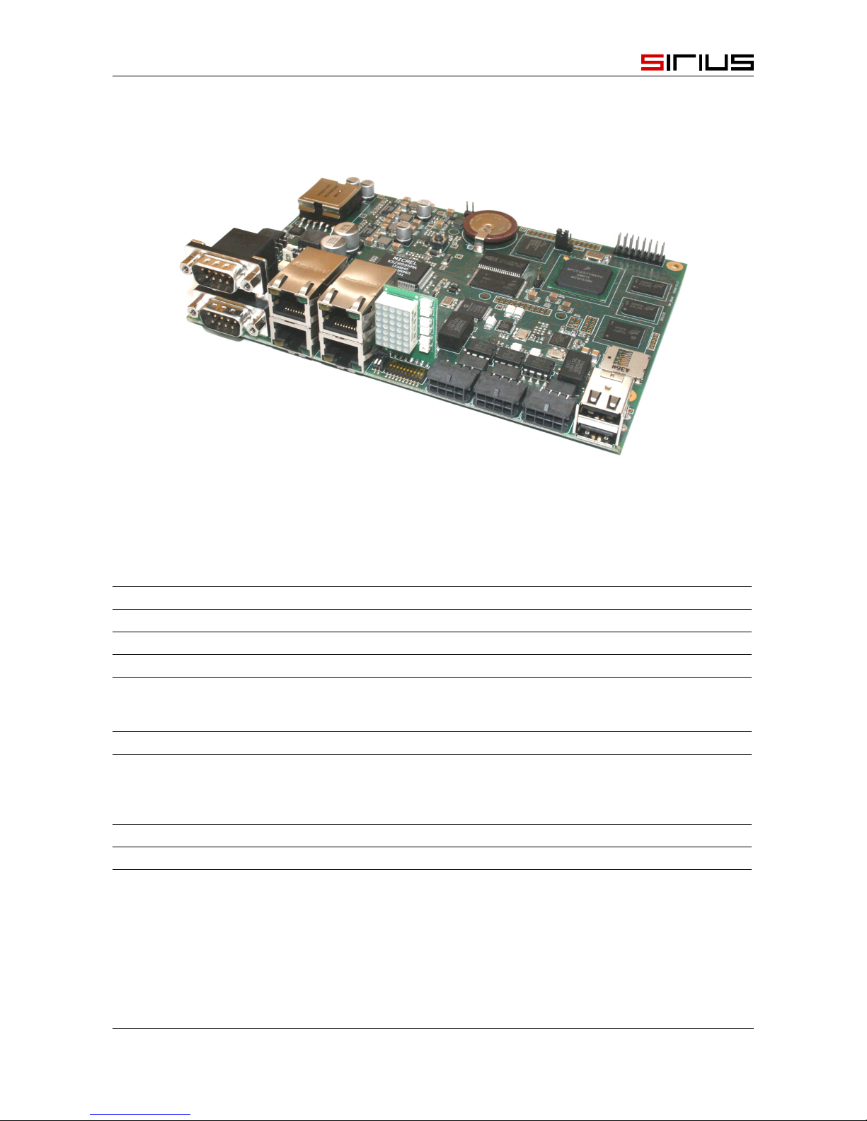
Sirius TagBoard DDT is a real time industrial computer.
The microprocessor is a MPC5125 PowerPC with a clock frequency of 400MHz, coupled with a 16-bit
PIC co-processor for the management of some non-critical tasks.
There are 256MB of DDR2 RAM, 8MB NOR for the kernel and boot, 2GB eMMC for the file system, 128kB
SRAM with battery backup and 1GB or 4GB NAND.
DDT has following communication interfaces:
• 3 optocoupled CANopen ports
• 1 10/100 ethernet port
• 1 three way 10/100 ethernet switch
• 2 optocoupled serial ports, configurables as RS232, 485 o 422 according to wiring
• 2 USB 2.0 ports
• 1 programmable dot matrix informative panel
• 1 microSD card slot
6
Page 7
TagBoard
2.2 Product images
Figure 2.1: DDT-A
2.3 Configuration
Description
CPU CPU MPC5125 400MHz
COPROCESSOR PIC 24HJ64GP506 16bit
RAM 256 MB DDR2
iNTERNAL STORAGE 1-4GB NAND Flash
2GB eMMC
128kB SRAM
STORAGE microSD card slot
COMMUNICATION 4 RJ45 Ethernet ports
2 USB 2.0 type A ports
2 RS232/485/422 COM ports
3 CANopen ports
POWER SUPPLY 24Vdc optocoupled
ADDITIONAL FEAT. 7x5 Dot matrix display
Sirius Electronic Systems s.r.l. 7
Page 8
TagBoard
2.4 Specifications
2.4.1 Power supply
DDT-A
Input Voltage 16-34Vdc
2.4.2 UART Ports
DDT-A
Number 2
Type RS232 - RS485 - RS422 cable select
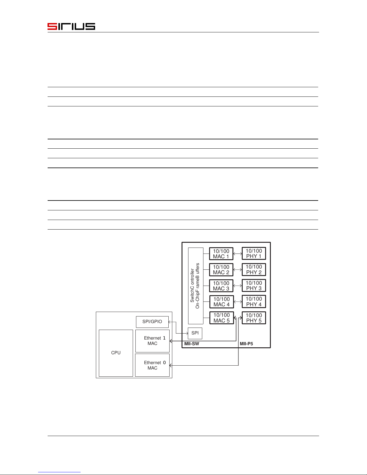
2.4.3 Ethernet Ports
DDT-A
ETH0 1x RJ45 Ethernet port 10/100
ETH1 3x RJ45 Ethernet switch 10/100
Ethernet
MAC
CPU
SwitchC ontro
ller
On-ChipF
rameB uffers
MII-SW
10/100
PHY 5
MII-P5
10/100
MAC 1
10/100
MAC 2
10/100
MAC 3
10/100
MAC 4
10/100
MAC 5
10/100
PHY 1
10/100
PHY 2
10/100
PHY 3
10/100
PHY 4
SPI/GPIO
SPI
Ethernet
MAC
1
0
Figure 2.2: Ethernet configuration
8 Sirius Electronic Systems s.r.l.
Page 9

TagBoard
2.4.4 CAN Ports
DDT-A
Number
3
Type
3 CANopen Master/Slave selectable
Signals
CANH, CANL, GND
Insulation
CAN interface circuits and +5 Vdc supply for CAN are optically
insulated from CPU
Format
CAN V2.0b physical layer for high-speed connection compliant
Data
in according CANopen CIA DS301
Address selection
1 channel is determined by dip-switch
Stub
121 ohm hardware selectable
2.4.5 Status Indicators
DDT-A
CAN status
green and red leds, in according with CAN indicator specification
DR303-3
NAND status
Solid red when NAND is used
Power ON
Solid green when power on
PIC status
Flashing red when Co-processor is operating
ACM matrix
Customizable 5x7 led dot matrix
2.4.6 Protections
DDT-A
Reverse polarity logic circuit, serie diode
power circuit, serie diode
Short circuit logic circuit, 500mA fuse
2.4.7 Mechanical & Environmental
DDT-A
Size (L x W) 160 x 114 mm
Height 15 mm
Weight 161 g
Ambient temperature 0 to +45 ºC operating, -40 to +85 ºC storage
Humidity 0 to 95%, non condensing
Sirius Electronic Systems s.r.l. 9
Page 10

TagBoard
2.4.8 Agency Conformance
DDT-A
CE CE compliant
61000_6_4 Generic standards - Emission Standard for industrial environments
61000_6_2 Generic standards - Immunity for industrial environments
ROHS RO HS Compliant
10 Sirius Electronic Systems s.r.l.
Page 11

TagBoard
2.5 Lights
There are three active leds to indicate the status of the board.
CON13
CON15
CON12
CON14
S1
JP2
S2
L11
J1
J2
CON10
JP_USB
L27
L49
U103
L3
C72
L6
J29
U76
J30
U19
U20
U21
CON9
J15
R733
R731
U23
U24
C261
C16
U61
U58
U62
U60
C71 C76
DL6
DL7
R774
R776
C17
C81
R497
R495
C402
C264
C265
C267
C260
S3
C560
C485
R773
C561
C286
X7
C563 C564
R738
R734
C492
R735
J19
U106
U85
OP38
OP36
OP40
OP26
OP27
OP28
P1
R764
C570
U128
C572
U109
R798 R742
R741
X3
C487 C488
U102
DL5
R403
C5
R406
C136
C168
C355 C275
RR24
OP41
R515
R779
C567
C574
C577
C573
R786
R780
R785
C575
C539
R758
U71
C283
X1
L20
C174
R651
C175
R672
C169
R701
C167
C165
L19
L21
VDR1
F1
CON8
J5
J4
R771
R772
C576
C571
R784
R787
DL3
R364 R301
DL2
R500
TP12
C284
C148
C164
R652
C171 C173 C177
C170
CE78
U78
JP1
J39
D60
D61
C137
C149
C14
C166
C144
R654
C484
C483
X6
R343
R770
C20
R541
R286
C19
R719
C6
C142
U1
R752
R682
L22
R427
U77
R745
C29
C197
C9
U41
C201
C143
R635
R648
R649
C141
R645
R640
R647
R641
R695
R743
R684
C139
R693
CE79
C412
MF11
R428
R429
U32
R756
J42
C147
C138
C135
C176
R643
R644
C162
R632
R642
R646
R631
C583
C439
C434
R552
TP11
D51
L51
CU107
L16
C172
R616
L45
C477
R551
R548
C437
C435
U30
U43
TP7
SW1
R617
R514
U96
C425
CE109
C436
C428
C476
U79
R545
R544
R550
U31
J16
R510
TP6
C613
C470
C582
L44
R547
R549
R546
C461
C426
TP10
T1
C408
C410
R513
C409
U90
R512
U97
R619
R620
R618
C581
C430
C423
C427
C372
U75
R511
C559
TP8
TP4
L29
C472
R438
R435
R543
C366
C422
L43
C205
C206
U88
J41
BT1A
L47
C453
C455
R553
R490
U3
R557
R744
R559
C416
CE83
C360
C357
U82
R763
R436
R434
J3
J10
C406
J6
C584
D59
C442
TP9
C580
L30
C471
R443
R542
C359
C419
CE106
CE82
J28
J40
TP5
TP2
C420
R440
C358
TP3
DDT_REL03 SIRIUSES.IT
BABABA
B
B
B
A
A
A
P
1
A
A
BA
14
12/11/12
BA
B
Figure 2.3: Lights position
LED Color Description
DL 2 RE D On when accessing NAND memory
DL 3 GR EEN On when 5Vdc power supply is present
DL 5 RE D Blinks when co-processor is operating
DL 6 GR EEN -
DL 7 GR EEN -
Sirius Electronic Systems s.r.l. 11
Page 12

TagBoard
2.6 ACM informative panel
There is a programmable information panel called ACM. Its location is shown in Figure 2.4
CON13
CON15
CON12
CON14
S1
JP2
S2
L11
J1
J2
CON10
JP_USB
L27
L49
U103
L3
C72
L6
J29
U76
J30
U19
U20
U21
CON9
J15
R733
R731
U23
U24
C261
C16
U61
U58
U62
U60
C71 C76
DL6
DL7
R774
R776
C17
C81
R497
R495
C402
C264
C265
C267
C260
S3
C560
C485
R773
C561
C286
X7
C563 C564
R738
R734
C492
R735
J19
U106
U85
OP38
OP36
OP40
OP26
OP27
OP28
P1
R764
C570
U128
C572
U109
R798 R742
R741
X3
C487 C488
U102
DL5
R403
C5
R406
C136
C168
C355 C275
RR24
OP41
R515
R779
C567
C574
C577
C573
R786
R780
R785
C575
C539
R758
U71
C283
X1
L20
C174
R651
C175
R672
C169
R701
C167
C165
L19
L21
VDR1
F1
CON8
J5
J4
R771
R772
C576
C571
R784
R787
DL3
R364 R301
DL2
R500
TP12
C284
C148
C164
R652
C171 C173 C177
C170
CE78
U78
JP1
J39
D60
D61
C137
C149
C14
C166
C144
R654
C484
C483
X6
R343
R770
C20
R541
R286
C19
R719
C6
C142
U1
R752
R682
L22
R427
U77
R745
C29
C197
C9
U41
C201
C143
R635
R648
R649
C141
R645
R640
R647
R641
R695
R743
R684
C139
R693
CE79
C412
MF11
R428
R429
U32
R756
J42
C147
C138
C135
C176
R643
R644
C162
R632
R642
R646
R631
C583
C439
C434
R552
TP11
D51
L51
CU107
L16
C172
R616
L45
C477
R551
R548
C437
C435
U30
U43
TP7
SW1
R617
R514
U96
C425
CE109
C436
C428
C476
U79
R545
R544
R550
U31
J16
R510
TP6
C613
C470
C582
L44
R547
R549
R546
C461
C426
TP10
T1
C408
C410
R513
C409
U90
R512
U97
R619
R620
R618
C581
C430
C423
C427
C372
U75
R511
C559
TP8
TP4
L29
C472
R438
R435
R543
C366
C422
L43
C205
C206
U88
J41
BT1A
L47
C453
C455
R553
R490
U3
R557
R744
R559
C416
CE83
C360
C357
U82
R763
R436
R434
J3
J10
C406
J6
C584
D59
C442
TP9
C580
L30
C471
R443
R542
C359
C419
CE106
CE82
J28
J40
TP5
TP2
C420
R440
C358
TP3
DDT_REL03 SIRIUSES.IT
BABABA
B
B
B
A
A
A
P
1
A
A
BA
14
12/11/12
BA
B
Figure 2.4: ACM panel position
Information panel is made of:
• 5x7 dot matrix display with customizable messages
• Three led pairs that provide CAN status information
Figure 2.5: ACM panel view
12 Sirius Electronic Systems s.r.l.
Page 13

TagBoard
LED Colore Description
DL 1 GR EEN CAN 1 Status Led
DL 2 RE D CAN 1 Error Led
DL 3 GR EEN CAN 2 Status Led
DL 4 RE D CAN 2 Error Led
DL 5 GR EEN CAN 3 Status Led
DL 6 RE D CAN 3 Error Led
The specifications of lights during operation of the device reflect what indicated in the document
CiA DR 303-3 v1.2.
5x7 dot matrix panel D1 is programmable in order to create custom messages.
Co processor operates the matrix following a map of bits positioned in the CPU.
Sirius Electronic Systems s.r.l. 13
Page 14

TagBoard
2.7 Selectors
CON13
CON15
CON12
CON14
S1
JP2
S2
L11
J1
J2
CON10
JP_USB
L27
L49
U103
L3
C72
L6
J29
U76
J30
U19
U20
U21
CON9
J15
R733
R731
U23
U24
C261
C16
U61
U58
U62
U60
C71 C76
DL6
DL7
R774
R776
C17
C81
R497
R495
C402
C264
C265
C267
C260
S3
C560
C485
R773
C561
C286
X7
C563 C564
R738
R734
C492
R735
J19
U106
U85
OP38
OP36
OP40
OP26
OP27
OP28
P1
R764
C570
U128
C572
U109
R798 R742
R741
X3
C487 C488
U102
DL5
R403
C5
R406
C136
C168
C355 C275
RR24
OP41
R515
R779
C567
C574
C577
C573
R786
R780
R785
C575
C539
R758
U71
C283
X1
L20
C174
R651
C175
R672
C169
R701
C167
C165
L19
L21
VDR1
F1
CON8
J5
J4
R771
R772
C576
C571
R784
R787
DL3
R364 R301
DL2
R500
TP12
C284
C148
C164
R652
C171 C173 C177
C170
CE78
U78
JP1
J39
D60
D61
C137
C149
C14
C166
C144
R654
C484
C483
X6
R343
R770
C20
R541
R286
C19
R719
C6
C142
U1
R752
R682
L22
R427
U77
R745
C29
C197
C9
U41
C201
C143
R635
R648
R649
C141
R645
R640
R647
R641
R695
R743
R684
C139
R693
CE79
C412
MF11
R428
R429
U32
R756
J42
C147
C138
C135
C176
R643
R644
C162
R632
R642
R646
R631
C583
C439
C434
R552
TP11
D51
L51
CU107
L16
C172
R616
L45
C477
R551
R548
C437
C435
U30
U43
TP7
SW1
R617
R514
U96
C425
CE109
C436
C428
C476
U79
R545
R544
R550
U31
J16
R510
TP6
C613
C470
C582
L44
R547
R549
R546
C461
C426
TP10
T1
C408
C410
R513
C409
U90
R512
U97
R619
R620
R618
C581
C430
C423
C427
C372
U75
R511
C559
TP8
TP4
L29
C472
R438
R435
R543
C366
C422
L43
C205
C206
U88
J41
BT1A
L47
C453
C455
R553
R490
U3
R557
R744
R559
C416
CE83
C360
C357
U82
R763
R436
R434
J3
J10
C406
J6
C584
D59
C442
TP9
C580
L30
C471
R443
R542
C359
C419
CE106
CE82
J28
J40
TP5
TP2
C420
R440
C358
TP3
DDT_REL03 SIRIUSES.IT
BABABA
B
B
B
A
A
A
P
1
A
A
BA
14
12/11/12
BA
B
J31
J32
J35
J36
Figure 2.6: Location of selectors
Selector Description
J31 CAN 1 terminating resistor
J32 CAN 2 terminating resistor
J35 UART0 terminating resistor when in RS485 mode
J36 UART1 terminating resistor when in RS485 mode
14 Sirius Electronic Systems s.r.l.
Page 15

TagBoard
2.8 Micro SD slot
CON13
CON15
CON12
CON14
S1
JP2
S2
L11
J1
J2
CON10
JP_USB
L27
L49
U103
L3
C72
L6
J29
U76
J30
U19
U20
U21
CON9
J15
R733
R731
U23
U24
C261
C16
U61
U58
U62
U60
C71 C76
DL6
DL7
R774
R776
C17
C81
R497
R495
C402
C264
C265
C267
C260
S3
C560
C485
R773
C561
C286
X7
C563 C564
R738
R734
C492
R735
J19
U106
U85
OP38
OP36
OP40
OP26
OP27
OP28
P1
R764
C570
U128
C572
U109
R798 R742
R741
X3
C487 C488
U102
DL5
R403
C5
R406
C136
C168
C355 C275
RR24
OP41
R515
R779
C567
C574
C577
C573
R786
R780
R785
C575
C539
R758
U71
C283
X1
L20
C174
R651
C175
R672
C169
R701
C167
C165
L19
L21
VDR1
F1
CON8
J5
J4
R771
R772
C576
C571
R784
R787
DL3
R364 R301
DL2
R500
TP12
C284
C148
C164
R652
C171 C173 C177
C170
CE78
U78
JP1
J39
D60
D61
C137
C149
C14
C166
C144
R654
C484
C483
X6
R343
R770
C20
R541
R286
C19
R719
C6
C142
U1
R752
R682
L22
R427
U77
R745
C29
C197
C9
U41
C201
C143
R635
R648
R649
C141
R645
R640
R647
R641
R695
R743
R684
C139
R693
CE79
C412
MF11
R428
R429
U32
R756
J42
C147
C138
C135
C176
R643
R644
C162
R632
R642
R646
R631
C583
C439
C434
R552
TP11
D51
L51
CU107
L16
C172
R616
L45
C477
R551
R548
C437
C435
U30
U43
TP7
SW1
R617
R514
U96
C425
CE109
C436
C428
C476
U79
R545
R544
R550
U31
J16
R510
TP6
C613
C470
C582
L44
R547
R549
R546
C461
C426
TP10
T1
C408
C410
R513
C409
U90
R512
U97
R619
R620
R618
C581
C430
C423
C427
C372
U75
R511
C559
TP8
TP4
L29
C472
R438
R435
R543
C366
C422
L43
C205
C206
U88
J41
BT1A
L47
C453
C455
R553
R490
U3
R557
R744
R559
C416
CE83
C360
C357
U82
R763
R436
R434
J3
J10
C406
J6
C584
D59
C442
TP9
C580
L30
C471
R443
R542
C359
C419
CE106
CE82
J28
J40
TP5
TP2
C420
R440
C358
TP3
DDT_REL03 SIRIUSES.IT
BABABA
B
B
B
A
A
A
P
1
A
A
BA
14
12/11/12
BA
B
Figure 2.7: MicroSD slot location
The position of the MicroSD cage slot is shown in figure 2.7
Sirius Electronic Systems s.r.l. 15
Page 16

TagBoard
2.9 Connections
CON13
CON15
CON12
CON14
S1
JP2
S2
L11
J1
J2
CON10
JP_USB
L27
L49
U103
L3
C72
L6
J29
U76
J30
U19
U20
U21
CON9
J15
R733
R731
U23
U24
C261
C16
U61
U58
U62
U60
C71 C76
DL6
DL7
R774
R776
C17
C81
R497
R495
C402
C264
C265
C267
C260
S3
C560
C485
R773
C561
C286
X7
C563 C564
R738
R734
C492
R735
J19
U106
U85
OP38
OP36
OP40
OP26
OP27
OP28
P1
R764
C570
U128
C572
U109
R798 R742
R741
X3
C487 C488
U102
DL5
R403
C5
R406
C136
C168
C355 C275
RR24
OP41
R515
R779
C567
C574
C577
C573
R786
R780
R785
C575
C539
R758
U71
C283
X1
L20
C174
R651
C175
R672
C169
R701
C167
C165
L19
L21
VDR1
F1
CON8
J5
J4
R771
R772
C576
C571
R784
R787
DL3
R364 R301
DL2
R500
TP12
C284
C148
C164
R652
C171 C173 C177
C170
CE78
U78
JP1
J39
D60
D61
C137
C149
C14
C166
C144
R654
C484
C483
X6
R343
R770
C20
R541
R286
C19
R719
C6
C142
U1
R752
R682
L22
R427
U77
R745
C29
C197
C9
U41
C201
C143
R635
R648
R649
C141
R645
R640
R647
R641
R695
R743
R684
C139
R693
CE79
C412
MF11
R428
R429
U32
R756
J42
C147
C138
C135
C176
R643
R644
C162
R632
R642
R646
R631
C583
C439
C434
R552
TP11
D51
L51
CU107
L16
C172
R616
L45
C477
R551
R548
C437
C435
U30
U43
TP7
SW1
R617
R514
U96
C425
CE109
C436
C428
C476
U79
R545
R544
R550
U31
J16
R510
TP6
C613
C470
C582
L44
R547
R549
R546
C461
C426
TP10
T1
C408
C410
R513
C409
U90
R512
U97
R619
R620
R618
C581
C430
C423
C427
C372
U75
R511
C559
TP8
TP4
L29
C472
R438
R435
R543
C366
C422
L43
C205
C206
U88
J41
BT1A
L47
C453
C455
R553
R490
U3
R557
R744
R559
C416
CE83
C360
C357
U82
R763
R436
R434
J3
J10
C406
J6
C584
D59
C442
TP9
C580
L30
C471
R443
R542
C359
C419
CE106
CE82
J28
J40
TP5
TP2
C420
R440
C358
TP3
DDT_REL03 SIRIUSES.IT
BABABA
B
B
B
A
A
A
P
1
A
A
BA
14
12/11/12
BA
B
Figure 2.8: DDT-A connectors
1 2 3 4 5
6 7 8 9
1 2 3 4 5
6 7 8 9
Figure 2.9: DDT-A communication ports
16 Sirius Electronic Systems s.r.l.
Page 17

TagBoard
The connectors are distributed on the perimeter of the card occupying two sides. All coomunication
ports are located on the long side of the card, while the power supply connector is located laterally.
2.9.1 CON8 - Power supply
12345
678910
Figure 2.10: MICROFI T 3.0 4304 51000
pin name type description
1 comune - 0V power supply reference
2 24V I N 24V power supply
3 GND - ground
4 NC - not connected
5 WDO - OU T negative side watchdog
6 comune - 0V power supply reference
7 24V I N 24V power supply
8 GND - ground
9 NC - not connected
10 WDO + OUT positive side watchdog
2.9.2 CON10 - Serial ports
1 2 3 4 5
6 7 8 9
1 2 3 4 5
6 7 8 9
CON10-B
CON10-A
Figure 2.11: DSUB 9 PINS
Sirius Electronic Systems s.r.l. 17
Page 18

TagBoard
pin name type description
1 NC - Not connected
2 RXD IN Receive data 232
3 TXD O UT Transmit data 232
4 NC - Not connected
5 GND - Ground
6 VC RX + IN Receive data 422 +
7 VC TX + O UT Transmit data 422 +
8 VC RX - IN Receive data 422 -
9 VC TX - OUT Transmit data 422 -
RS485 communication is cable dependent
2.9.3 CON12- CANopen CAN 0
1234
5678
Figure 2.12: MICROFI T 3.0 4304 50800
pin name type description
1-5 CH+ IN/O UT CAN high
2-6 CH- IN/OUT CAN low
3-7 CAN
reference
- 0V CAN reference
4-8 CAN
reference
- 0V CAN reference
2.9.4 CON13 - CANopen CAN 1
1234
5678
Figure 2.13: MICROFI T 3.0 4304 50800
18 Sirius Electronic Systems s.r.l.
Page 19

TagBoard
pin name type description
1-5 CH+ IN/O UT CAN high
2-6 CH- IN/OUT CAN low
3-7 CAN
reference
- 0V CAN reference
4-8 CAN
reference
- 0V CAN reference
Sirius Electronic Systems s.r.l. 19
Page 20

TagBoard
2.9.5 CON14 - CANopen CAN 2
1234
5678
Figure 2.14: MICROFI T 3.0 4304 50800
pin name type description
1-5 CH+ IN/O UT CAN high
2-6 CH- IN/OUT CAN low
3-7 CAN
reference
- 0V CAN reference
4-8 CAN
reference
- 0V CAN reference
2.9.6 CON15 - Double USB 2.0 connector
Figure 2.15: USB 2.0 TYPE A
pin name type description
1 Vbus OU T + 5Vdc
2 D - IN/OUT Data -
3 D + IN/OUT Data +
4 GND - Ground
2.9.7 J1/J2 - Ethernet Hub
Figure 2.16: 10/100 RJ45 ET HE RNE T FOU R P ORTS
20 Sirius Electronic Systems s.r.l.
Page 21

TagBoard
pin name type description
1 TX + OU T Transmit data +
2 TX - O UT Transmit data -
3 RX + IN Receive data +
4 NC - Not connected
5 NC - Not connected
6 RX - IN Receive data +
7 NC - Not connected
8 NC - Not connected
2.10 Dip-switch
Dip-switch S location is shown in figure.
CON13
CON15
CON12
CON14
S1
JP2
S2
L11
J1
J2
CON10
JP_USB
L27
L49
U103
L3
C72
L6
J29
U76
J30
U19
U20
U21
CON9
J15
R733
R731
U23
U24
C261
C16
U61
U58
U62
U60
C71 C76
DL6
DL7
R774
R776
C17
C81
R497
R495
C402
C264
C265
C267
C260
S3
C560
C485
R773
C561
C286
X7
C563 C564
R738
R734
C492
R735
J19
U106
U85
OP38
OP36
OP40
OP26
OP27
OP28
P1
R764
C570
U128
C572
U109
R798 R742
R741
X3
C487 C488
U102
DL5
R403
C5
R406
C136
C168
C355 C275
RR24
OP41
R515
R779
C567
C574
C577
C573
R786
R780
R785
C575
C539
R758
U71
C283
X1
L20
C174
R651
C175
R672
C169
R701
C167
C165
L19
L21
VDR1
F1
CON8
J5
J4
R771
R772
C576
C571
R784
R787
DL3
R364 R301
DL2
R500
TP12
C284
C148
C164
R652
C171 C173 C177
C170
CE78
U78
JP1
J39
D60
D61
C137
C149
C14
C166
C144
R654
C484
C483
X6
R343
R770
C20
R541
R286
C19
R719
C6
C142
U1
R752
R682
L22
R427
U77
R745
C29
C197
C9
U41
C201
C143
R635
R648
R649
C141
R645
R640
R647
R641
R695
R743
R684
C139
R693
CE79
C412
MF11
R428
R429
U32
R756
J42
C147
C138
C135
C176
R643
R644
C162
R632
R642
R646
R631
C583
C439
C434
R552
TP11
D51
L51
CU107
L16
C172
R616
L45
C477
R551
R548
C437
C435
U30
U43
TP7
SW1
R617
R514
U96
C425
CE109
C436
C428
C476
U79
R545
R544
R550
U31
J16
R510
TP6
C613
C470
C582
L44
R547
R549
R546
C461
C426
TP10
T1
C408
C410
R513
C409
U90
R512
U97
R619
R620
R618
C581
C430
C423
C427
C372
U75
R511
C559
TP8
TP4
L29
C472
R438
R435
R543
C366
C422
L43
C205
C206
U88
J41
BT1A
L47
C453
C455
R553
R490
U3
R557
R744
R559
C416
CE83
C360
C357
U82
R763
R436
R434
J3
J10
C406
J6
C584
D59
C442
TP9
C580
L30
C471
R443
R542
C359
C419
CE106
CE82
J28
J40
TP5
TP2
C420
R440
C358
TP3
DDT_REL03 SIRIUSES.IT
BABABA
B
B
B
A
A
A
P
1
A
A
BA
14
12/11/12
BA
B
Figure 2.17: Posizione del dip-switch su DDT-A
2.10.1 Address selection
Using S1 selector it is possible to change the CAN address of the device.
Assigned address is stored in variable CobId.
Sirius Electronic Systems s.r.l. 21
Page 22

TagBoard
Address can be a number from 0 to 127. Every CAN node must have an unique address.
Follows bit weight:
Switch Peso
S2 ON 1
S3 ON 2
S4 ON 4
S5 ON 8
S6 ON 16
S7 ON 32
S8 ON 64
Table 2.1: dip-switch weight
2.10.2 Communication speed selection
Using S1 selector it is possible to change the communication speed of the device.
Assigned speed is stored in variable CobBR.
Speed can be 125, 250, 500 or 1000 kbps.
S10 S9 Baud rate
kbps
OFF O FF 125
OFF ON 250
ON OFF 500
ON ON 1000
Table 2.2: baud rate selection
22 Sirius Electronic Systems s.r.l.
Page 23

TagBoard
FCC Statement
Note: This equipment has been tested and found to comply with the limits for a Class A digital device,
pursuant to part 15 of the FCC Rules. These limits are designed to provide reasonable protection
against harmful interference when the equipment is operated in a commercial environment. This
equipment generates, uses, and can radiate radio frequency energy and, if not installed and used in
accordance with the instruction manual, may cause harmful interference to radio communications.
Operation of this equipment in a residential area is likely to cause harmful interference in which case
the user will be required to correct the interference at his own expense.
Changes or modifications not expressly approved by the party responsible for compliance could void
the user’s authority to operate the equipment.
Industry Canada statement
This device complies with Industry Canada licence-exempt RSS standard(s). Operation is subject to
the following two conditions:
1. this device may not cause interference, and
2. this device must accept any interference, including interference that may cause undesired
operation of the device.
Le présent appareil est conforme aux CNR d’Industrie Canada applicables aux appareils radio exempts de licence. L’exploitation est autorisée aux deux conditions suivantes :
1. l’appareil ne doit pas produire de brouillage, et
2. l’utilisateur de l’appareil doit accepter tout brouillage radioélectrique subi, même si le brouil-
lage est susceptible d’en compromettre le fonctionnement.
CAN ICES-3 (A)/NMB-3(A)
Sirius Electronic Systems s.r.l. 23
Page 24

Chapter 3
Software
3.1 Operating system
With the Sirius TagBoard DDT comes a "Unix-like" operating system based on the Linux kernel, version
3.9.4. The current release of the kernel ensures complete compatibility with all parts of the TagBoard.
The kernel image is compliant with the GNU GPLv2 license, and is then distributed along with its source
code.
The Linux kernel is designed to be compatible with the IEEE POSIX interprocess communication. This
allows users to compile most of the existing Unix programs and run them.
The distribution is based on the Yocto Project and allows the management of applications through
packets, as in Linux distributions for desktop systems.
The applications developed in userspace can use all the system libraries provided by OpenEmbedded / Yocto. These libraries have been released under the LGPL license, so that the developer has
the option to assign the preferred license to his own software. In userspace, there are no implications
or dependencies enforced with proprietary software.
The operating system integrates Xenomai scheduler to guarantee real-time performance.
24
Page 25

TagBoard
3.2 Device Drivers
The operating system integrates the drivers for all devices on the Tag Board.
The device drivers are provided as modules and are also compatible with the GPLv2 license. In the
event that it is necessary to design and implement a new driver, will be evaluated from time to time
with the type of license which can be distributed, in accordance with the client.
3.3 Real-Time constraints
To ensure to processes desired real-time constraints, in addition to the Linux traditional preemptive
scheduler, is also present a further scheduler called Xenomai. This solution provides a set of APIs that
allow you to create processes with real-time characteristics entirely in userspace, greatly simplifying
the implementation and debugging of the entire project. To manage priorities between tasks in real
time, Xenomai scheduler supports both FIFO and Round-Robin policies.
Xenomai makes the Linux kernel a "hard real time" operating system. This allows the designer to
develop real-time tasks as abstract cells, independent from the non real time system part, so that
those have no coexistence issues (race conditions, starvation, ...).
In the practice Xenomai provides determinism on the scheduling of real-time tasks and interrupt response with acceptable latency for real time applications, in the order of 100us.
Xenomai also solves the problem of the microprocessor overload caused by the real-time scheduler,
which may impair the ability to perform communication with, for example, other peripheral devices,
serial ports or on the CAN bus.
It is therefore possible to develop real-time device drivers (RTDM API) providing deterministic access
to the communication pipes, maximizing the speed.
The architecture and implementation of the Xenomai APIs follow the logic diagram shown in figure
Figure 3.1: Architecture
The implementation of real-time tasks and communication with the core functions, occur using interfaces compatible with:
• VxWorks
Sirius Electronic Systems s.r.l. 25
Page 26

TagBoard
• pSOS
• uITRON
• VRTX
• POSIX
For more information about the communication between processes is possible to consult the document Native-API-tour-rev-C.pdf, present on the site www.xenomai.org
3.4 Development Environment
3.4.1 IDE
The toolchain IDE is Eclipse. It takes care of starting the compilation and debug it. In Eclipse Git is also
included.
The toolchain in a Microsoft Windows environment is released by Sirius.
3.4.2 Repository
For each board produced, Sirius keeps updated the operating system, checking periodically and
incorporating bug fixes or proposed changes through customer feedback.
The management of all components of the operating system software (services, drivers, and utilities)
is via the opkg package manager.
The server that contains the packages of the distribution (O PKG) for TAGBOARD is maintained by Sirius
in open source form. This server also contains the Git repository on which it is published the history of
the distribution and toolchain tags, from which the customer can collect the information about latest
versions and choose whether to adopt them.
3.4.3 Debug
software architecture is so diveded:
• kernel space
• user space
To hide the complexity of the operating system the applications run in user space, with easily debuggable special real-time threads.
In the event of a system crash the kernel is able to indicate the point of failure to take appropriate
decisions.
3.5 Update
Each operating system application (drivers included) or a specific application developed by or for a
customer, is structured in packages.
This allows you to keep track of versions of each package and use the ethernet network to update
the project under development.
26 Sirius Electronic Systems s.r.l.
Page 27

TagBoard
3.6 Licenses
kernel Linux GPLv2
librerie di sistema LGPL
applicazioni di sistema GPLv2/GPLv3
driver Sirius into kernel core GPLv2
driver Sirius out of kernel core vary according to the agreements with customers
applicazioni in user space vary according to the agreements between customer and developer
applicazioni in kernel space GPLv2
Sirius Electronic Systems s.r.l. 27
 Loading...