

Page 1

V e h i c l e K i t
Installation & User Guide
Page 2

Congratulations on the Purchase of your new SIRIUS Stiletto
Vehicle Kit!
The Stiletto Vehicle Kit will maximize your safety and provide convenience by posit ioning the
Stiletto for easy viewing and operation. Whether you c hoose the FM wireless or dire ct connect option when installi ng the kit, the rich digital sound of SIRIUS radio will pl ay through your
vehicle’s stereo system. The vehicle dock features pre set and direct tune buttons f or quickly
tuning to your favorite c hannels, and a jump button fo r tuning directly to the traf fic/weather
channel for your area. It is designed for professional or self-installation, and in cludes a vent
and dash mount for flexib le mounting options. Use this manual as a guide for the in stallation.
The SIRIUS Stiletto Vehic le Kit will work with the Sti letto model satellite radios.
For the latest informatio n about this and other SIRIUS products and accessories, vi sit
http://www.sirius.com.
Page 3

Table of Contents
TABLE OF CONTENTS . . . . . . . . . . . . . . . . . . . . . . . . . . . . . . 3
WARNING AND SAFETY INFORMATION . . . . . . . . . . . . . . . . . . . . . . 4
FCC Caution . . . . . . . . . . . . . . . . . . . . . . . . . . . . . . . . . . 4
FCC Interference Statement . . . . . . . . . . . . . . . . . . . . . . . . . . . .4
Safety Precautions . . . . . . . . . . . . . . . . . . . . . . . . . . . . . . . .5
Warnings . . . . . . . . . . . . . . . . . . . . . . . . . . . . . . . . . . . 6
PACKAGE CONTENTS . . . . . . . . . . . . . . . . . . . . . . . . . . . . . . 7
CONTROLS . . . . . . . . . . . . . . . . . . . . . . . . . . . . . . . . . . 9
Vehicle Dock . . . . . . . . . . . . . . . . . . . . . . . . . . . . . . . . . . 9
Remote Control Reference Guide . . . . . . . . . . . . . . . . . . . . . . . . . 11
Remote Control Battery Installation . . . . . . . . . . . . . . . . . . . . . . . 15
INSTALLATION . . . . . . . . . . . . . . . . . . . . . . . . . . . . . . . . 16
Installing the Vehicle Kit . . . . . . . . . . . . . . . . . . . . . . . . . . . . . 16
Installing the Antenna . . . . . . . . . . . . . . . . . . . . . . . . . . . . . 21
Connecting the Cigarette Lighter Adapter . . . . . . . . . . . . . . . . . . . . . 24
Docking and Un-docking the Stiletto . . . . . . . . . . . . . . . . . . . . . . . 25
Maximizing Audio Quality From Your Stiletto Radio . . . . . . . . . . . . . . . . . . 26
Wireless Connection . . . . . . . . . . . . . . . . . . . . . . . . . . . . 26
Direct Connections . . . . . . . . . . . . . . . . . . . . . . . . . . . . . 39
Subscribing to the SIRIUS Service . . . . . . . . . . . . . . . . . . . . . . . . 42
OPERATION . . . . . . . . . . . . . . . . . . . . . . . . . . . . . . . . . 43
Presets . . . . . . . . . . . . . . . . . . . . . . . . . . . . . . . . . . . 43
Direct Channel Tuning . . . . . . . . . . . . . . . . . . . . . . . . . . . . . 44
Jump Feature . . . . . . . . . . . . . . . . . . . . . . . . . . . . . . . . . 45
TROUBLESHOOTING . . . . . . . . . . . . . . . . . . . . . . . . . . . . . 46
OPTIONAL ACCESSORIES . . . . . . . . . . . . . . . . . . . . . . . . . . . 47
WARRANTY . . . . . . . . . . . . . . . . . . . . . . . . . . . . . . . . . 48
SPECIFICATIONS . . . . . . . . . . . . . . . . . . . . . . . . . . . . . . . 49
COPYRIGHTS & TRADEMARKS . . . . . . . . . . . . . . . . . . . . . . . . 50
SIRIUS ID . . . . . . . . . . . . . . . . . . . . . . . . . . . . . . . . . . 51
[ Tab le of Co nte nts ]
3
Page 4

Warning and Safety Information
FCC Caution
Any changes or modificati ons not expressly approved by the party responsible for co mpliance
could void the user’s aut hority to operate this equipm ent.
This device complies with part 15 of the FCC Rules.
Operation is subject to t he following two conditions:
This device may not cause harmful interference, and
1.
This device must accept a ny interference received, inc luding interference that may cause
2.
undesired operation.
This transmitter must not be co-located or operating i n conjunction with any other antenna or
transmitter.
FCC Interference Statement
This equipment has been t ested and found to comply wit h the limits for a Class B di gital device, pursuant to Part 15 of the FCC Rules. These limi ts are designed to provide re asonable
protection against harmfu l interference in a residenti al installation. This equipme nt generates,
uses and can radiate radi o frequency energy and, if no t installed and used in accor dance with
the instructions, may cau se harmful interference to ra dio communications. However, there is
no guarantee that interfe rence will not occur in a par ticular installation. If this equipment does
cause harmful interferenc e to radio or television rece ption, which can be determine d by turning the equipment off and on, the user is encouraged t o try to correct the interfer ence by one
of the following measures :
Reorient or relocate the receiving antenna.
—
Increase the separation b etween the equipment and rece iver.
—
Connect the equipment int o an outlet on a circuit diff erent from that to which the receiver
—
is connected.
Consult the dealer or an experienced radio/TV technici an for help.
—
[ War nin g and Sa fety Inf ormat ion ]
4
Page 5

Safety Precautions
Be sure to observe the fo llowing warnings. Failure to follow these safety instructi ons and
warnings may result in a serious accident and/or perso nal injury.
•
Installation must be perf ormed according to this insta llation guide. SIRIUS is not responsible for issues arising from installations not perfor med according to the procedur es in this
guide.
•
Do not operate the SIRIUS radio in a way that might di vert your attention from driv ing
safely. As a driver, you alone are responsible for saf ely operating your vehicle in accordance with traffic safety laws at all times.
Do not install the unit w here it may obstruct your vie w through the windshield, or of your
•
vehicle’s indicator displ ays.
•
Do not install the unit w here it may hinder the functi on of safety devices such as an airbag.
Doing so may prevent the airbag from functioning prope rly in the event of an accide nt.
•
To avoid short circuits, do not open the unit, and nev er put or leave any metallic objects
(coins, tools, etc.) insi de the unit.
•
If the unit emits smoke o r unusual odors, turn the pow er off immediately, and disco nnect
the unit from any power s ource.
•
Do not drop the unit or s ubject it to strong shocks.
•
The installation and use suggestions contained in this installation manual are subj ect
to any restrictions or li mitations that may be imposed by applicable law. The purch aser
should check applicable l aw for any restrictions or li mitations before installing a nd/or
operating this unit.
•
Do not install the FM Ext ender Cable where it will hin der or block your view. In so me
states it may be illegal to mount it on the windshield of your vehicle. Check appli cable law
for any restrictions or l imitations before installing the extender cable on your wi ndshield.
•
Do not install the FM Ext ender Cable where it may hind er the function of safety dev ices
such as an airbag. Doing so may prevent the airbag fro m functioning properly in the event
of an accident.
[ War nin g and Sa fety Inf ormat ion ]
5
Page 6

Warnings
Noti ce To Dri vers In C alifornia and Minn esota
State law prohibits drive rs in California and Minnesot a from using suction mounts o n their
windshields while operati ng motor vehicles. Other dash board or friction mounting op tions
should be used. SIRIUS do es not take any responsibilit y for any fines, penalties, o r damages
that may be incurred as a result of disregarding this notice. (See California Vehic le Code Section 26708(a); Minnesota Statutes 2005, Section 169.71 )
Oper ating Tem perature
The SIRIUS Cigarette Ligh ter Adapter is designed to op erate between -20° to +85° C (-4° to
+185° F). Avoid leaving i t in a vehicle or elsewhere w here the temperature may fall outside
this range.
Clea ning and Maintenan ce
If the vehicle dock becom es dirty, turn the power off and wipe it clean with a soft cloth. Do
not use hard cloths, stro ng cleaning fluids, paint thi nner, alcohol, or other volat ile solvents to
clean. These may cause da mage to the unit.
Ciga rette Lig hter Adap ter
The vehicle dock cannot b e powered directly from a veh icle’s 12 VDC power system. It must
be powered using the incl uded Cigarette Lighter Adapte r only. Connecting the vehicl e dock
directly to the vehicle’s 12 VDC power system may resu lt in damage to the vehicle d ock or
SIRIUS radio, or both.
[ War nin g and Sa fety Inf ormat ion ]
6
Page 7
Package Contents
1
preset tune jump
2 3 4 5
6
7 8 9 0
1 2 3
+
4 5 6
7 8 9
jump
preset
options display
back home
mute
tune
FM
0
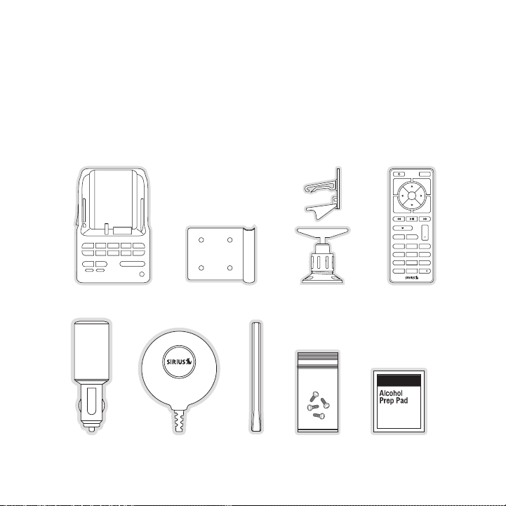
The following items are i ncluded with your purchase of the SIRIUS Stiletto Vehicle Kit.
Unpack the kit carefully and make sure that everything shown is present. If anythin g is missing
or damaged, or if the kit fails to operate properly, n otify your dealer immediately . It is recommended that you retain th e original carton and packing materials in case you need t o ship your
kit in the future.
Cigar ette L ighter
Vehic le Doc kVehic le Doc k Vehic le Mou ntsVehic le Mou nts
Adapt er
Adapt er
Magne tic
Magne tic
Anten na
Anten na
Vehic le Doc k
Vehic le Doc k
Finge r Grip
Finge r Grip
Cover /Tail
Cover /Tail
Anten na
Anten na
Mount ing
Mount ing
Screw s
Screw s
Remot e Cont rolRemot e Cont rol
Alcoh ol Swa bAlcoh ol Swa bCigar ette L ighter
[ Pac kag e Con ten ts ]
7
Page 8
[ Pac kag e Con ten ts ]
8
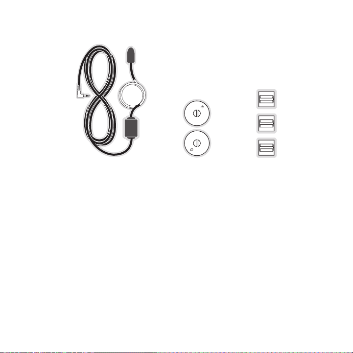
Sucti on Cup s (2)Sucti on Cup s (2)FM Ex tender CableFM Ex tender Cable
Self Adhesi ve
Self Adhesi ve
Cable Guide s (3)
Cable Guide s (3)
Page 9
Controls
1
preset tune jump
2 3 4 5
6
7 8 9 0
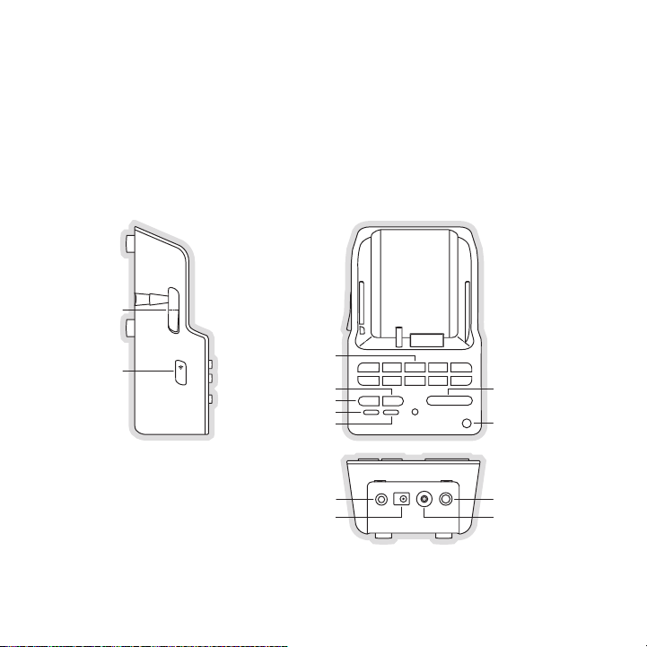
FM
lock
Direct Entry Tune/
Preset Buttons
Preset
Tune
DC5V
LINE OUT
FM
Lock
Jump
IR Remote
Sensor
Preset Mode Indicator
Tune Mode Indicator
FM OUT
ANT
Figur e 1Figur e 1
Vehicle Dock
Figure 1 and the table fo llowing identify and describe the buttons, connectors, and features of
the vehicle dock.
[ Con tro ls ]
9
Page 10

Butt on/
Conn ector
0 – 9
tune
pres et
jump
FM
Lock
FM O UT
DC 5 V
LINE OUT
ANT
Vehi cle D ock Button an d Connect or Descri ptions
Acti on Desc ripti on
In T une Mode: Directly se lects the channel indicted by the numbers which were pressed
Press
In P reset Mode: Selects p resets 0 – 9
Changes to the direct tun ing mode where channel number s may
Press
be entered
Changes to the preset mod e and displays the list of pr eset
channels
Press
The second and subsequent press cycles through the pre set
banks, A, B, and C
Jumps to a preselected tr affic/weather channel
Press
A second press returns to the previous channel or song /show
Displays the FM Frequency screen where the FM transmit ter
Press
frequency can be selected , or an FM preset selected us ing the
0 – 9 buttons
Toggle Secures the Stiletto in the v ehicle dock
This connection is used f or the FM Extender Cable (or optional FM Direct
Adapter which directly co nnects to the vehicle’s FM ra dio antenna input)
Connection for the Cigare tte Lighter Adapter
Audio output for direct c onnection to the vehicle’s au dio system. An audio
cable (not supplied) is r equired to utilize this conne ction
Connection for the Magnet ic Antenna
10
[ Con tro ls ]
Page 11
Remote Control Reference Guide
1 2 3
+
4 5 6
7 8 9
jump
preset
options display
back home
mute
tune
FM
0
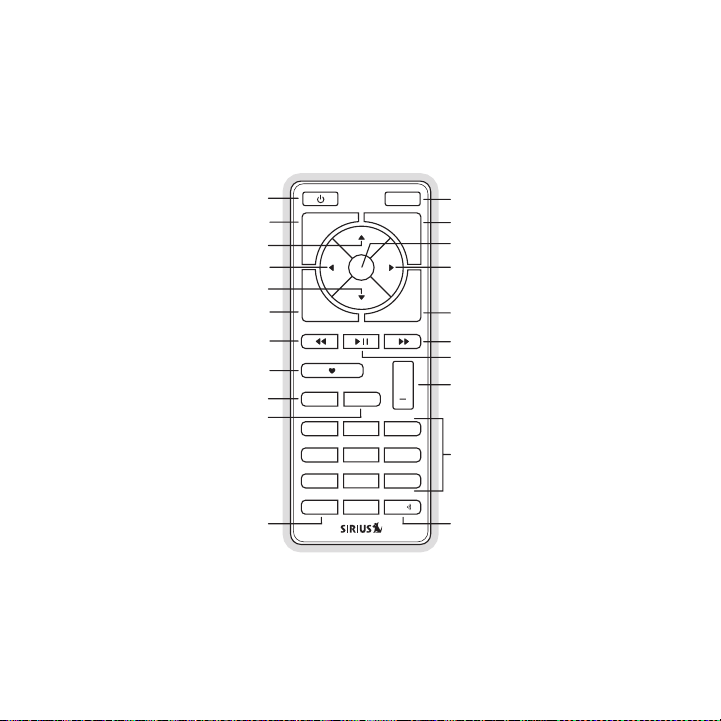
Select
FM
Jump
Preset
Tune
Media Dial (CCW)
Media Dial (CW)
Power
Love
Back
Options
Rewind
Rewind
Volume
Numeric
Keypad
Fast-Forward
Fast-Forward
Display
Home
Mute
Play/Pause
Figur e 2Figur e 2
Figure 2 and the table fo llowing identify and describe the buttons of the remote co ntrol. The
remote control works when the Stiletto is in the vehic le dock.
[ Con tro ls ]
11
Page 12
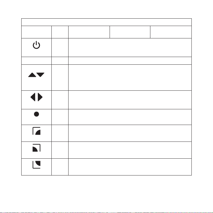
Butt on Acti on
Remo te Co ntro l Button Descripti ons
Sate llite Rad io
Envi ronme nt
Inte rnet Radi o
Envi ronme nt
Repl ay/Li brar y
Envi ronme nt
Up/D own
Left /Righ t
opti ons
12
Powe r
Mute
Sele ct
back
home
[ Con tro ls ]
Press Turns the Stiletto On/Off
Press Mutes (or un-mutes) the audio
Pressing Up is equivalent to turning the Media Dial counter-clockwise
Pressing Down is equivale nt to turning the Media Dial clockwise
Press
If listening, displays ch annel or category list
If in a list, menu, or pr ompt, scrolls to next or prev ious item
Pressing Right is equival ent to Fast-Forward
Press
Pressing Left is equivale nt to Rewind
Press Selects highlighted item in a list, menu, or pr ompt
Returns back to the scree n displayed just prior to the currently
Press
displayed screen
First press returns to th e Home screen
Press
Additional press returns to the Now Playing screen
Displays available option s for the currently displayed screen
Press
If no options are availab le, nothing is displayed
Page 13
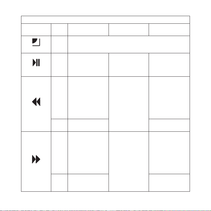
Butt on
disp lay
Play /Paus e
Rewi nd
Fast -Forw ard
Remo te Co ntro l Button Descripti ons Conti nued
Acti on
Sate llite Rad io
Envi ronme nt
Inte rnet Radi o
Envi ronme nt
Cycles between 3-channel display mode, 6-channel displ ay
Press
mode, artist name, and so ng title when in the channel browsing
mode
If playing, mutes
audio
If muted, resumes
playing
Press
Pauses a broadcast
or resumes playing
a paused broadcast
If listening, rewinds
Press
Hold
a broadcast to the
previous song or
show
If in a channel or
preset list, moves
through categories
or preset banks
If listening, rewinds
through a broadcast
If listening and
muted, resumes
playing
If in a channel or
category list, moves
through channel
categories
If listening, fast-forwards in the replay
Press
Hold
buffer to the next
song or show
If in a channel or
preset list, moves
through categories
or preset banks
Fast-Forwards
through the replay
If listening and
muted, resumes
playing
If in a channel or
category list, moves
through channel
categories
buffer
Repl ay/Li brar y
Envi ronme nt
Pauses or resumes
playing the current
song or show
Skips to the beginning of the song or
show
Rewinds through
song or show
Skips to the next
song or show
Fast-Forwards
through song or
show
[ Con tro ls ]
13
Page 14

Butt on
Love
+/–
Volu me
pres et
tune
0 - 9
Remo te Co ntro l Button Descripti ons Conti nued
Acti on
Press
Hold
Press
Press
Press
Press
Sate llite Rad io
Envi ronme nt
Saves the song or
show if possible,
or adds to favorites
when song/show
cannot be saved
While recording,
prompts to stop
recording
Displays recording
setup screen
While recording,
prompts to stop
recording
+ increases the audio vol ume
— decreases the audio vol ume
Changes to the preset mod e and displays the list of pr eset channels
A second and subsequent p ress cycles through the prese t
banks, A, B, and C
Changes to the direct tun ing mode where channel number s may
be entered
In T une Mode: Directly se lects the channel indicted by the numbers which are pressed
In P reset Mode: Selects p resets 0 –9
Inte rnet Radi o
Envi ronme nt
Adds the artist/song to t he favorites list
Repl ay/Li brar y
Envi ronme nt
14
[ Con tro ls ]
Page 15
Remo te Co ntro l Button Descripti ons Conti nued
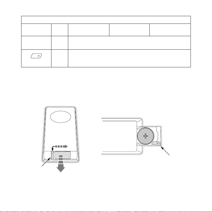
FM
Latch Tab
Latch Tab
+
Figur e 3Figur e 3
Butt on
jump
FM
Rem ote C ont Rol Bat teRy In stal latI on
To install the remote con trol battery, locate the batt ery drawer on the bottom edge . Open
the battery drawer by hol ding the latch tab to the rig ht and sliding the drawer out as shown
in Figure 3. Place the ba ttery in drawer with the + si de of the battery facing up a nd slide the
drawer back into the remo te control.
Acti on
Press
Press
Sate llite Rad io
Envi ronme nt
Jumps to a preselected tr affic/weather channel
A second press returns to the previous channel or song /show
Displays the FM Frequency screen where the FM transmit ter
frequency can be selected , or an FM preset selected us ing the
0–9 buttons
Inte rnet Radi o
Envi ronme nt
Repl ay/Li brar y
Envi ronme nt
[ Con tro ls ]
15
Page 16

Installation
SIRIUS suggests professio nal installation of this prod uct in your vehicle. Professi onal installation provides an experi enced technician to install t his product in your vehicle, advice for
selecting a suitable moun ting location, installation o f the antenna, and routing al l the necessary wires and cables. An installer will have the nece ssary audio connection access ories to
provide optimal audio out put of the SIRIUS radio direc tly to your vehicle’s audio s ystem. Ask
your SIRIUS retailer if t hey provide professional inst allation services, or can rec ommend a
professional installation service.
Installing the Vehicle Kit
When installing the vehic le dock, choose a location in your vehicle where the radio will not
block your vision, interf ere with the vehicle controls , or obstruct the air bag. Th e location
should be easily accessib le and provide good visibilit y of the display, and should not be
located where it will be in direct sunlight which will affect the visibility of the display screen.
The left side of the vehi cle dock which has the Lock a nd FM FM buttons should also n ot be
obstructed.
The mounting accessories necessary to install the vehi cle dock in a vehicle are pro vided.
Figure 4 shows two exampl es of the Stiletto mounted in a vehicle: A is the console mount
method using the adhesive mount, and B is the vent mou nt method.
16
[ Ins tal latio n ]
Page 17

2
3
4
5
1
o
p
t
i
o
n
s
d
i
s
p
l
a
y
b
a
c
k
h
o
m
e
7
8
9
0
6
p
r
e
s
e
t
t
u
n
e
j
u
m
p
A.
B.
2
3
4
5
1
o
p
t
i
o
n
s
d
i
s
p
l
ay
b
a
c
k
h
o
m
e
7
8
9
0
6
p
r
e
s
e
t
t
u
n
e
j
u
m
p
Depending upon the mounti ng method you select, the mou nt should be assembled as
Figur e 4Figur e 4
described in one of the f ollowing two sections. In cho osing a mounting location, be sure that
position chosen will not block access to the Lock and FM FM buttons on the side o f the
vehicle dock.
Cons ole M ount Method ( A)
To assemble and mount the vehicle dock for the console mount method A as shown in F igure
4:
Attach the adhesive foot to the vehicle dock using the provided screws, placing the
1.
finger grip between the a dhesive foot and the vehicle dock. (Figure 5)
Before adhering the mount to the console, be s ure to select your mounti ng position care-
2.
fully because once the mo unt has been adhered to a sur face, it will not be possible to
remove it and adhere it a gain.
Clean the selected mounti ng surface area in the vehicl e with the alcohol swab.
3.
Unscrew the adhesive foot from the mounting bracket. P eel the protective material o ff
4.
the adhesive on the foot and press the foot firmly aga inst the vehicle surface.
The adhesive mount should then be allowed to adhere fo r a minimum of 2-4 hours befo re
5.
use. Best adhesion occurs after 24 hours. When the adh esive foot has achieved sufficient adhesion, reattac h the vehicle dock to the foo t.
[ Ins tal latio n ]
17
Page 18

Mounting
Bracket
Vehicle
Dock
Finger
Grip
FM
lock
A
dhesive
Foot
FM
lock
Figur e 5Figur e 5
18
[ Ins tal latio n ]
Page 19

Vent Moun t Me thod (B)
Figur e 6Figur e 6
To assemble and mount the vehicle dock for the vent mo unt method B as shown in Figu re 4:
Assemble the vent mount c lip as shown in Figure 6. Not e that the lower arm may be a t-
1.
tached in two different p ositions. You should assemble the vent clip in the configu ration
that works best in your p articular vehicle. Figure 6 i llustrates both possible conf igurations of the vent clip.
Attach the vent clip to t he vehicle dock using the pro vided screws, placing the fin ger
2.
grip between the vent cli p and the vehicle dock. (Figu re 7)
Slide the vent clip porti on of the mount into a vent i n your vehicle, insuring that one of
3.
the vent louvers slides b etween the upper and lower po rtions of the two clip arms, and
hooks the rear of the lou ver.
[ Ins tal latio n ]
19
Page 20

Vent Clip
Clip Arms
Vehicle
Dock
Finger
Grip
FM
lock
FM
lock
Figur e 7Figur e 7
20
[ Ins tal latio n ]
Page 21

Installing the Antenna
Figur e 8Figur e 8
The optimum mounting loca tion for the magnetic antenna is on the roof of the vehicl e, with a
minimum unobstructed area of 12 inches by 12 inches, a nd exactly 6½ inches from the rear
roof edge of the vehicle (the length of the rubber ant enna cable cover/tail). It is important to
avoid any obstructions th at will block the SIRIUS sign al, obstructions such as a ro of rack,
a sunroof, roof mounted c argo containers, or other ant ennas. For convertible vehicl es, the
antenna should be install ed on the trunk lid.
For best performance, it is recommended that the anten na be installed with the rubb er
antenna cable cover/tail. This rubber antenna cable co ver/tail provides two benefit s: first, it
positions the antenna the recommended distance from th e rear window, rear door/hatc h, or
trunk edge to give the an tenna the best view of the sk y. Secondly, it conceals and protects
the exposed antenna cable . The rubber antenna cable co ver/tail has adhesive strips that hold
it securely in place.
The following illustratio ns show the recommended mount ing locations of the antenna for
several types of vehicles . (Figure 8) Follow these rec ommendations for best perform ance from
the antenna.
Seda n/Co upe. Mount the antenna along the rear center-line of the vehicle roof, located at the
rear of the roof near the rear window.
Pick up T ruck. Mount the a ntenna along the rear center- line of the cab roof, located at the
rear of the roof near the rear window.
SUV/ Mini -Van. Mount the a ntenna along the rear center- line of the vehicle roof, loc ated at the
rear of the roof near the rear door/hatch.
[ Ins tal latio n ]
21
Page 22

Rubber Antenna
Cover/Tail
Protective
Strips
Adhesive
Strain
Relief
Cable
Figur e 9Figur e 9
Figur e 10Figur e 10
Conv erti ble. Mount the an tenna along the center-line o f the trunk lid, with the rub ber antenna
cable cover/tail directed toward the rear window.
When you have selected a suitable mounting location, c lean the area where the anten na and
rubber antenna cable cove r/tail will be mounted with t he supplied alcohol swab.
Connect the rubber antenn a cable cover/tail to the ant enna cable, making sure that the strainrelief on the antenna sit s into the rubber antenna cab le cover/tail groove. (Figure 9) Route the
antenna cable through the wire channel in the rubber a ntenna cable cover/tail. Do n ot remove
the protective strips yet .
Temporarily position the antenna and rubber antenna ca ble cover/tail in the selecte d mounting
area and route the cable from the antenna to the vehic le’s interior by tucking it u nderneath the
rubber molding around rea r window, as shown in Figure 10.
Route the cable from the lowest point of the rear wind ow into the trunk. Take advan tage of
any existing cable channe ls or wiring conduits. For SU Vs, mini-vans and 5-door vehi cles, bring
the cable into the vehicl e under the rubber molding fo r the tailgate, and continue under the
interior trim.
From the trunk, or rear o f the vehicle, route the cabl e around the passenger compar tment and
to the front of the vehic le, to the radio. Take care n ot pull the cable across shar p edges that
could damage it, and keep it away from areas where it might entangle feet. Coil any excess
[ Ins tal latio n ]
22
Page 23

antenna cable in a locati on where it can be hidden. Co nnect the antenna cable to th e AN T
Figur e 11Figur e 11
connection at the rear of the vehicle dock. (Refer to Figure 12 on page 24 for the location of
this connector.)
Once the antenna cable is routed through the vehicle, and you are satisfied with th e cable
routing, peel the protect ive material from the adhesiv e strips and press the rubber antenna
cable cover/tail firmly i nto place on the vehicle. Dou ble check that the location o f the antenna
and rubber antenna cable cover/tail are correct, and c ontinue to press firmly down on rubber antenna cable cover/t ail for another 30 seconds. ( Figure 11) At room temperatur e (68
degrees), maximum adhesio n usually occurs within 72 ho urs. During this period, avoi d car
washes and other contact with the antenna and rubber a ntenna cable cover/tail.
[ Ins tal latio n ]
23
Page 24

Connecting the Cigarette Lighter Adapter
DC5V
LINE OUT
FM OUT
ANT
Figur e 12Figur e 12
Connect the provided ciga rette lighter adapter to the DC5V connection at the rear o f the
vehicle dock. (Figure 12)
Do not use any other powe r adapter for the vehicle doc k, or connect it directly to the vehicle’s
power. Doing so will dama ge the vehicle dock and the S tiletto. Using anything other than the
supplied cigarette lighte r adapter to power the vehicl e dock will void the warranty .
24
[ Ins tal latio n ]
Page 25

Docking and Un-docking the Stiletto
back
home
display
options
1
preset tune jump
2 3 4 5
6
7 8 9 0
Satellite Radio
Internet Radio
Library
Figur e 13Figur e 13
When docking the Stiletto , be sure the Lock button of the vehicle dock is in the un locked
position. (Refer to Figur e 1 on page 9 for the locatio n of the Lock button.) Grasp the vehicle
dock with your free hand and place the Stiletto into t he vehicle dock, as shown in Figure
13, and slide it down unt il it is fully seated. Place the Lock button into the lock ed position to
secure the Stiletto in th e vehicle dock.
To remove the Stiletto fr om the vehicle dock place the Lock button in the unlocked position.
Grasp the vehicle dock wi th your free hand and pull th e Stiletto up until it diseng ages from
the vehicle dock.
[ Ins tal latio n ]
25
Page 26

Maximizing Audio Quality From Your Stiletto Radio
90.1
There are two primary way s to connect your SIRIUS radi o to your vehicle radio: Wire less
Conn ecti on or Direct Conn ecti on. The following section s will help you obtain the be st perfor-
mance. For the latest inf ormation go to http://www.sir ius. com/ vehi cleinstallation.
WIR ele ss Co nne CtI on
Your SIRIUS radio contain s an FM transmitter. The FM t ransmitter sends the audio fr om your
SIRIUS radio to your vehi cle radio. (Figure 14)
Figur e 14Figur e 14
Included with your SIRIUS radio is an FM Extender Cabl e to maximize the audio quali ty of
your SIRIUS radio when us ing a wireless audio connecti on. Should the wireless audio quality
without the FM Extender C able be not acceptable, you c an try using the FM Extender Cable
(or opt for a direct conn ection).
Wire less Audi o Connect ion Witho ut the FM Extender Cable
To tune your vehicle’s FM radio and your SIRIUS radio to the same FM channel (Figur e 14):
Turn off your Stiletto an d tune through the FM channel s on your vehicle’s FM radio to
1.
locate an FM channel that is not broadcasting in your area. If you use an FM channe l
that is being used by a l ocal broadcaster, it will int erfere with the performance o f your
SIRIUS radio. Once you ha ve located an FM channel that is not broadcasting in your
area, save it as a preset on your vehicle radio. This will become your SIRIUS prese t.
Power the Stiletto on. W hen it is completely powered up, press the FM FM button on
2.
[ Ins tal latio n ]
26
Page 27

the left side of the vehi cle dock or press the FM button on the remo te control.
90.1
FM Transmit
Turn the Media Dial to
change the frequency.
Use the number keys to
recall or assign FM presets
90.1 FM1
FM Transmit
Turn the Media Dial to
change the frequency.
Use the number keys to
recall or assign FM presets
Figur e 15Figur e 15
Figur e 16Figur e 16
Use the Media Dial o r the buttons on the remote con trol to select the same FM
3.
channel. (Figure 15) Pres s and hold a preset number (0 —9) on the vehicle dock in wh ich
you want to store the sel ected FM channel as a preset. (Figure 16) Press the Select
button to exit and transm it on the selected FM channel . The Stiletto will transmit on the
selected FM channel.
Note : The FM transmitter in your SIRIUS radio is autom atically set to FM channel 88 .1.
Note : The FM transmitter in your SIRIUS radio is autom atically set to FM channel 88 .1.
This may not be the best channel in your area.
This may not be the best channel in your area.
Tip: If you regularly tra vel between cities with diffe rent active FM channels, you may
Tip: If you regularly tra vel between cities with diffe rent active FM channels, you may
need to find channels tha t are not broadcasting in eac h city. The Stiletto can stor e mul-
need to find channels tha t are not broadcasting in eac h city. The Stiletto can stor e multiple FM transmit channel s as presets, so you can easi ly switch to the best FM chan nel
tiple FM transmit channel s as presets, so you can easi ly switch to the best FM chan nel
for each city. You will a lso want to set the FM channe ls that are not broadcasting in
for each city. You will a lso want to set the FM channe ls that are not broadcasting in
each city as presets on y our vehicle radio.
each city as presets on y our vehicle radio.
You should now hear the a udio from your SIRIUS radio o ver your vehicle’s FM radio. If the
audio quality is not sati sfactory, you should install the FM Extender Cable as desc ribed in the
following section (or use a direct connection as descr ibed on page 39).
Wire less Audi o Connect ion Using the FM E xtender C able
Included with your SIRIUS radio is an FM Extender Cabl e to maximize the audio quali ty of your
SIRIUS radio when using a wireless audio connection. P roper placement of the FM Ext ender
Cable inside your vehicle in close proximity to the ve hicle’s own FM antenna will p rovide
[ Ins tal latio n ]
27
Page 28

a strong FM signal for go od reception. The FM Extender Cable has suction cup mounts or
permanent adhesive mounts for installing it on your ve hicle’s window.
Because of the different types of FM antennas found in vehicles, and the varied loc ations of
the antenna in each vehic le, SIRIUS suggests professio nal installation of FM Extend er Cable
in your vehicle. Ask your SIRIUS retailer if they prov ide professional installation services, or
can recommend a professio nal installation service.
The FM antennas found in vehicles are of four distinct types:
Aeri al T ype Fender Mounte d FM
•
Ante nna: A fixed or retra ctable aerial
antenna located on the fr ont or rear
fender of the vehicle.
Aeri al T ype Roof Mounted FM A n-
•
tenn a: A fixed aerial ant enna mounted
on the roof (often at the front or rear of
the roof, just above the window glass).
28
[ Ins tal latio n ]
Page 29

On G lass Type FM Antenna: Wires on
•
the window glass of the v ehicle, usually
near the top of the windo w. It may be
located on the windshield glass, the rear
window glass, or a rear s ide window in
some SUV and mini-van typ e vehicles
(and other vehicles). It will look similar to
the rear window defroster wires found in
many vehicles.
“Sha rk F in” Type FM Anten na: A device
•
resembling a shark fin (o r other shape)
located on the vehicle ro of above the rear
window.
[ Ins tal latio n ]
29
Page 30

Before attempting install ation, you should verify the type and location of the FM a ntenna in
Suction Cups
your particular vehicle. If you have trouble locating it, consult the manual which accompanied
your vehicle, consult a d ealer for your type of vehicl e, or consult a professional installer.
The FM Extender Cable sho uld be placed inside the vehi cle, as close as possible to the
vehicle’s FM antenna. A t est mounting should be done f irst using the included sucti on cup
mounts to test the instal lation. Once an acceptable lo cation has been found, you wi ll remove
the suction cups and perm anently adhere the FM Extende r Cable using the adhesive mo unts.
To install the FM Extende r Cable in your vehicle, foll ow these instructions:
Attach the suction cups t o the FM Extender Cable in th e positions shown in Figure 1 7.
1.
Figur e 17Figur e 17
In this step, follow the specific instructions in sub- step a, b, c, or d depending on the
2.
type of FM antenna in you r vehicle:
a. Installation Instructions for Vehicles with Aerial Type Fender Mounted FM Antenna.
For vehicles where the FM radio antenna is located on the front fender, the FM
Extender Cable should be mounted vertically on the fro nt windshield at the edge of
the glass nearest to the antenna. (Figure 18)
For vehicles where the FM radio antenna is l ocated on the rear fender, th e FM
Extender Cable should be mounted vertically on the rea r window at the edge of the
glass nearest to the ante nna. (Figure 19)
Attach the FM Extender Cable to the section of glass closest to the FM an tenna in
a vertical orientation. ( Figure 18 or Figure 19) The w ire between the two suction
cups should be pulled tau t and as straight as possible , and should not obstruct the
driver’s view.
30
[ Ins tal latio n ]
Page 31

Alternate mounting
location on adjacent
A-Pillar
Impo rtant Caution: In som e states it may not be legal to put the FM Extender
Impo rtant Caution: In som e states it may not be legal to put the FM Extender
Cable on the windshield g lass. In this case, the FM Ex tender Cable should be
Cable on the windshield g lass. In this case, the FM Ex tender Cable should be
mounted on the A-Pillar a djacent to the FM antenna.
mounted on the A-Pillar a djacent to the FM antenna.
Figur e 18Figur e 18
Figur e 19Figur e 19
[ Ins tal latio n ]
31
Page 32

b. Installation Instructions for Vehicles with Aerial Type Roof Mounted FM Antenna.
For vehicles where the FM radio antenna is located on the front or rear of the roof
of the vehicle, the FM Ex tender Cable should be mounte d horizontally on the front
or rear glass below the F M antenna, or installed into the headliner of the vehicle
under the FM antenna.
If you are installing the FM Extender Cable on the win dow glass, attach the suc-
•
tion cups to the glass un der the FM antenna in a horiz ontal orientation. The wire
between the two suction c ups should be pulled taut and as straight as possible,
and should not obstruct t he driver’s view. (Figure 20)
If you are installing the FM Extender Cable into the h eadliner, remove the suction
•
cups and tuck the wire in to the headliner, stretched t aut and straight, and centered under the FM antenn a.
Figur e 20Figur e 20
32
[ Ins tal latio n ]
Page 33

c. Installation Instr ucti ons for Vehicles with On Glas s Type FM Antenna.
For vehicles where the FM radio antenna is located on the window glass, the FM
Extender Cable can be mou nted horizontally on the glas s, directly over the FM
radio antenna, or install ed into the headliner of the vehicle directly above the FM
antenna.
If you are installing the FM Extender Cable on the win dow glass, attach the suc-
•
tion cups to the glass ce ntered over the FM radio ante nna in a horizontal orientation. The wire between th e two suction cups should be pulled taut and as straight
as possible, and should n ot obstruct the driver’s view . (Figure 21 & 22)
If you are installing the FM Extender Cable into the h eadliner, remove the suction
•
cups and tuck the wire in to the headliner, stretched t aut and straight, and centered above the FM antenn a.
Figur e 21Figur e 21
[ Ins tal latio n ]
33
Page 34

34
Figur e 22Figur e 22
[ Ins tal latio n ]
Page 35

d. Insta llat ion Instructions for Vehi cles wit h Shark Fin Type FM A nten na.
For vehicles where the FM radio antenna is located on the rear of the roof of the
vehicle, the FM Extender Cable should be mounted horiz ontally on the glass below
the FM antenna, or instal led into the headliner of the vehicle under the FM antenna .
If you are installing the FM Extender Cable on the win dow glass, attach the suc-
•
tion cups to the glass be low the FM antenna in a horiz ontal orientation. (Figure
23) The wire between the two suction cups should be pulle d taut and as straight
as possible, and should n ot obstruct the driver’s view .
If you are installing the FM Extender Cable into the h eadliner, remove the suction
•
cups and tuck the wire in to the headliner, stretched t aut and straight, and centered under the FM antenn a.
Figur e 23Figur e 23
[ Ins tal latio n ]
35
Page 36

Plug the FM Extender Cabl e into the F M OUT connector o f your Stiletto vehicle dock.
FM OUT
From FM Extender Cable
90.1
3.
(Figure 24)
Figur e 24Figur e 24
Tune your vehicle’s FM ra dio and your Stiletto to the same FM channel (Figure 25):
4.
a. Turn off your Stiletto and tu ne through the FM channels on your vehicle’s FM
radio to locate an FM cha nnel that is not broadcasting in your area. If you use
an FM channel that is bei ng used by a local broadcaste r, it will interfere with the
performance of your SIRIU S radio. Once you have locate d an FM channel that is
not broadcasting in your area, save it as a preset on your vehicle radio. This will
become your SIRIUS preset .
Figur e 25Figur e 25
36
[ Ins tal latio n ]
Page 37

90.1
FM Transmit
Turn the Media Dial to
change the frequency.
Use the number keys to
recall or assign FM presets
90.1 FM1
FM Transmit
Turn the Media Dial to
change the frequency.
Use the number keys to
recall or assign FM presets
Figur e 26Figur e 26
Figur e 27Figur e 27
b. Power t he Stiletto on. When it is c ompletely powered up, press the FM FM
button on the left side o f the vehicle dock or press t he FM button on the remote
control.
c. Use the Media Dial or the buttons on the remote control to select th e same
FM channel. (Figure 26) P ress and hold a preset number (0—9) on the vehicle dock
in which you want to stor e the selected FM channel as a preset. (Figure 27) Press
the Select button to exit and transmit on the selected FM channel. The Stiletto
will transmit on the sele cted FM channel.
Note : The FM transmitter in your SIRIUS radio is autom atically set to FM channel
Note : The FM transmitter in your SIRIUS radio is autom atically set to FM channel
88.1. This may not be the best channel in your area.
88.1. This may not be the best channel in your area.
Tip: If you regularly tra vel between cities with diffe rent active FM channels, you
Tip: If you regularly tra vel between cities with diffe rent active FM channels, you
may need to find channels that are not broadcasting in each city. The Stiletto can
may need to find channels that are not broadcasting in each city. The Stiletto can
store multiple FM transmi t channels as presets, so you can easily switch to the
store multiple FM transmi t channels as presets, so you can easily switch to the
best FM channel for each city. You will also want to s et the FM channels that are
best FM channel for each city. You will also want to s et the FM channels that are
not broadcasting in each city as presets on your vehic le radio.
not broadcasting in each city as presets on your vehic le radio.
You should now hear the a udio from your SIRIUS radio o ver your vehicle’s FM radio. If
5.
the audio quality is not satisfactory, try moving the FM Extender Cable slightly to see if a
better signal can be obta ined.
If you are mounting the FM Extender Cable in the headliner of the vehicle, skip this step.
6.
When you are satisfied wi th the mounting location, rem ove the suction cup mounts an d
peel the backing off the adhesive mounts. Permanently adhere it in the same positio n on
the glass (or A-Pillar), keeping it taut and as straig ht as possible. (Figure 28)
[ Ins tal latio n ]
37
Page 38

Adhesive Adhesive
FM
Figur e 28Figur e 28
Route the antenna cable t o your SIRIUS radio. Use the included self adhesive cable
7.
guides (if necessary) to hold the antenna wire in plac e until it reaches the weathe r
stripping or moulding at the edge of the window. Take advantage of any existing cab le
channels or wiring condui ts and route the cable around the passenger compartment to
the vehicle dock. Take ca re not pull the cable across sharp edges that could damage it,
and keep it away from are as where it might entangle fe et. Coil and secure any exces s
antenna cable in a locati on where it can be hidden and secured.
Plug the FM Extender Cabl e into the F M OUT connector o f your Stiletto vehicle dock
8.
(Refer to Figure 24 on pa ge 36.)
This completes the instal lation of the FM Extender Cab le.
To a ssign add itional F M channel s as FM p resets in your Sti letto:
Press the FM FM button on the left si de of the vehicle dock or pre ss the FM button
1.
on the remote control.
Use the Media Dial o r the buttons on the remote con trol to select an FM channel.
2.
Press and hold the preset number (0—9) in which you wa nt to store the selected FM
3.
channel. Repeat steps 2 a nd 3 to assign additional FM presets.
Press the Select button to ex it and transmit on the selected FM channel, or press t he
4.
FM button to simply exit .
If you’re not sure which FM channels are not broadcast ing in your home or travel ci ties, you
can also go to http://sir ius. com/ fmch annel and search for a suggested FM channel ba sed
on your zip code.
[ Ins tal latio n ]
38
Page 39

DIR eCt C onn eCt Ion s
FM
OFF
Figur e 29Figur e 29
A direct connection provi des better audio performance than a wireless connection an d
removes the possibility o f interference from local FM broadcasters. There are sever al ways to
directly connect your Sti letto which are explained in the following sections.
Tip: Depending on the mod el of radio in your vehicle a nd your level of comfort with in-car
Tip: Depending on the mod el of radio in your vehicle a nd your level of comfort with in-car
installations, a direct c onnection may require profess ional installation assistance . Ask your
installations, a direct c onnection may require profess ional installation assistance . Ask your
retailer or contact SIRIU S customer support for recomm ended installers in your area .
retailer or contact SIRIU S customer support for recomm ended installers in your area .
Dire ct Wi red Audio Con nection
If your vehicle radio off ers an “AUX IN” or “LINE IN” connection, it is the best au dio connection available. If the “A UX IN” or “LINE IN” connector is located on the front of y our vehicle
radio, this is also the e asiest connection. (Figure 29 )
Purchase an audio cable t hat matches the connection ty pe of your vehicle radio and your
1.
SIRIUS radio at your loca l electronics retailer. Your SIRIUS radio requires a 1/8” stereo
male connector. Your loca l electronics retailer can he lp you determine the proper c onnection for your vehicle radio.
Plug one end of the cable into the LI NE OUT jack on th e vehicle dock. (Refer to Fig ure
2.
12 on page 24.) Plug the other end into your “AUX IN” or “LINE IN” jack on your veh icle
radio.
Note : Refer to your vehic le radio manufacturer’s guide lines for correct installatio n.
Note : Refer to your vehic le radio manufacturer’s guide lines for correct installatio n.
If the “AUX IN” or “LINE IN” connection is on the bac k of your vehicle radio, you may
If the “AUX IN” or “LINE IN” connection is on the bac k of your vehicle radio, you may
Note :
Note :
want to consider professi onal installation. (Figure 30 )
want to consider professi onal installation. (Figure 30 )
[ Ins tal latio n ]
39
Page 40

FM
OFF
FM
OFF
Figur e 30Figur e 30
Figur e 31Figur e 31
Cass ette Adap ter
If your vehicle radio has a cassette player:
Purchase a Cassette Adapt er at your local electronics retailer.
1.
Connect the adapter betwe en the L INE OUT on the vehicl e dock (refer to Figure 12 on
2.
page 24), and the vehicle radio’s cassette slot. (Figu re 31)
Note : Refer to the casset te adapter manufacturer’s gui delines for correct use.Note : Refer to the casset te adapter manufacturer’s gui delines for correct use.
[ Ins tal latio n ]
40
Page 41

SIRI US FM Dir ect Adapt er
90.1
FM
DIRECT
ADAPTER
Vehicle FM
Antenna
Figur e 32Figur e 32
If your vehicle radio does not have an “AUX IN” or “LINE IN” jack, the SIRIUS FM Direct Adaptor
provides a wired connection between your Stiletto and your vehicle radio, eliminating the outside
static and interference you sometimes experience when using a wireless FM connection. (Figure
32) Professional installation may be required. See your local SIRIUS retailer. (The SIRIUS FM
Direct Adapter is available at your local SIRIUS retailer or at http://shop.sirius.com.)
[ Ins tal latio n ]
41
Page 42

00
112233445566
SID
Satellite
Figur e 33Figur e 33
Subscribing to the SIRIUS Service
Before you can listen to the SIRIUS service, you need to activate your subscription . To subscribe, do the following:
Before activating your St iletto, be sure you have inst alled the vehicle kit as desc ribed in
1.
the previous sections. Pl ace the Stiletto in the vehic le dock and power it on by sl iding
the Power/Lock switch down.
When the Stiletto has ful ly powered on, from the Home screen select Satellite Radio
2.
All Channels and tune to channel 184. The SIRIUS chan nel line-up will begin updating. Wait until the chann el updates have completed bef ore pressing any buttons.
Once the channels have be en updated, the display will change to Call 1-888-539-
3.
SIRI US to Subscribe. You should be able to hear audio from channel 184, the SIRIUS
Weather and Emergency cha nnel.
Use the Media Dial t o tune to channel 0 to displa y the Stiletto’s unique 1 2-digit
4.
SIRIUS ID Number (SID). ( Figure 33) The SID number is also available on the Stilett o’s
packaging, and may also b e accessed by selecting Setti ngs Devi ce Sirius ID.
Write the SID number down in the space provided near t he end of this installation g uide.
Have your credit card han dy and contact SIRIUS on the Internet at:
5.
https://acti vate .sir iusr adio.com/
and follow the prompts to activate your subscription. You can also call SIRIUS toll -free
at: 1-888-539-SIRIUS (1-8 88-539-7474).
When you have successfull y subscribed to the SIRIUS se rvice, and the Stiletto has b een
6.
updated with your subscri ption information, an alert w ill be displayed. To continue , press
the Select button.
You are now ready to begi n enjoying Sirius Satellite R adio’s digital entertainment, and can
tune to other channels!
42
[ Ins tal latio n ]
Page 43

preset
preset
Presets (B)
Margaritaville
Everywhere
Tim McGraw
B1
31
B2
Sirius
Disorder
24 Cure
For Love
Bonnie Raitt
B3
Roadhouse
62
Honky Tonk Song
Webb Pierce
B
Presets
Figur e 35Figur e 35
Figur e 34Figur e 34
Operation
Presets
Channel presets may be se lected using the vehicle dock to tune to a channel by push ing the
0—9 buttons when the vehi cle dock is in the preset mod e. The Stiletto must be in th e Satellite
Radio mode to select pres ets. To select to a preset:
Press the
1.
indicate that the preset mode is active.
Select the desired preset band (A, B, or C) by repeate dly pressing the
2.
ton until the desired pre set band is displayed. (Figur e 34)
Press one of the 0—9 butt ons to select the desired pre set
3.
OR
Use the Media Dial t o highlight a preset and pres s the Select button. (Figure 35)
Preset button on the veh icle dock. The preset mode in dicator light will
Preset but-
[ Ope rat ion ]
43
Page 44

Direct Channel Tuning
tune
Direct
Tune
26
Enter channel #
Figur e 37Figur e 37
Figur e 36Figur e 36
Channels may be tuned dir ectly by entering the channel number using the 0—9 buttons on the
vehicle dock when the veh icle dock is in the tune mode . The Stiletto must be in the Satellite
Radio mode to select chan nels. To directly tune a chan nel:
Press the
1.
light will indicate that the tune mode is active.
Enter the channel number of the desired channel. If a 3-digit channel number is ent ered,
2.
the channel will be tuned immediately. If only one or two digits are entered, the c hannel
will be tuned after a sli ght pause. (Figure 37)
Tune button on the vehic le dock. (Figure 36) The tune mode indicator
44
[ Ope rat ion ]
Page 45

Jump Feature
jump
jump
jump
jump
jump
jump
jump
148
Satellite
NY Traffic
Traffic &
Weather
Traffic & Weather
Atlanta
Baltimore
Boston
Chicago
Dallas / Fort Worth
Detroit
Figur e 38Figur e 38
Figur e 40Figur e 40
Figur e 39Figur e 39
The
Jump button on the vehic le dock allows you to jump to a pre-selected traffic/
weather report for your l ocation. The Stiletto must be in the Satellite Radio mode to use the
jump feature.
When the
Jump button is pressed, the traffic/weather report wi ll be tuned. (Figures 38
& 396) If the traffic/wea ther report for your location is not immediately available , a Waiting for
loca l report message will be displayed to indicate a j ump is active. Once your loca l report is
ready, the Stiletto will automatically tune to the tra ffic/weather report.
Pressing the
search. Pressing the
Jump button while the tr affic/weather report is pendi ng will cancel the
Jump button after the ra dio has tuned to your traffic /weather report will return back to the channel to which you had been tuned immediately prior to pressing
the
The traffic/weather repor t for your location is associ ated with the
the Settings menu. If you press the
Jump button.
Jump button using
Jump button, but have no t yet selected a traffic/weather location, you will be prompted to select a location from a list of avai lable cities.
(Figure 40)
[ Ope rat ion ]
45
Page 46

Troubleshooting
Symp tom Solu tion
SIRIUS radio does not
power on
SIRIUS radio displays:
Ante nna Not Detected
SIRIUS radio displays:
Acqu iring Signal
Audio static or loss of
clarity
No sound The vehicle dock is not c onnected or is incorrectly co nnected
Blown fuse, or the vehicl e dock does not have power or is not
properly connected.
Check the cigarette light er adapter connection. Refer to the
vehicle’s owners manual f or the location of the vehicl e’s fuse
panel and check for a blo wn fuse.
The satellite antenna is not connected to the vehicle dock.
Check the satellite anten na connection to the vehicle dock.
The Stiletto is searching for a satellite signal.
Check for obstacles over or around the satellite anten na.
Change the vehicle locati on to eliminate nearby obstac les
(bridges, overpasses, tre ss, buildings, etc).
The FM channel contains s tatic.
Locate a unused FM channe l on your vehicle radio and s et the FM
transmitter frequency of the SIRIUS radio to match.
If using a direct connect ion, check the cable connecti ons.
Refer to the section, Max imiz ing Audi o Quality From Yo ur
Stil etto Radio.
to the vehicle’s sound sy stem. Refer to the section Ma ximi zing
Audi o Qu ality From Your S tile tto Radi o and follow the instructions carefully.
[ Tro ubl eshoo tin g ]
46
Page 47

Optional Accessories
The following optional ac cessories are available for p urchase from your SIRIUS reta iler to
maximize your SIRIUS Stil etto experience:
Home Kit (Mod el SLH1)
The Stiletto Home Kit is a compact home dock that prov ides everything you
need to use the Stiletto in your home or office. The s leek home dock provides a convenient way to charge your Stiletto’s batte ry along with an extra
slot for charging a spare battery. The included indoor /outdoor antenna
provides improved recepti on, while audio cables enable you to connect the
Stiletto to amplified spe akers or a home entertainment system.
The kit includes a compac t tabletop/desktop home dock with FM output for wireless c onnectivity, a remote contr ol, audio cables, an adjustable indoor/outdoor win dowsill antenna with
20’ of cable, and an AC A dapter. Detailed installation instructions are included wi th the kit.
Exec utive Sou nd System (Model S LEX1)
The Stiletto Executive So und System is a portable dock ing
station and audio system for use with the Stiletto rad io. With
the built-in amplifier an d speakers, the system delive rs rich,
powerful sound indoors or outdoors, and features an au xiliary
input for other audio dev ices. Included with the syste m is an
adjustable indoor/outdoor windowsill antenna with 20’ of cable and an AC adapter.
FM D irect Ada pter (Pro duct No. 14100)
The FM Direct Adapter dir ectly connects the FM signal from your SIRIUS radio to you r
vehicle’s AM/FM radio, re ducing any interference which might be present from FM rad io station broadcasts. When the SIRIUS radio is turned off, the vehicle’s FM antenna is a utomatically connected back to t he vehicle’s AM/FM radio. The adapter connects directly in -line with
the vehicle’s existing AM /FM antenna input. SIRIUS rec ommends professional installa tion of
this product.
[ Opt ion al Ac ces sorie s ]
47
Page 48

Warranty
12 M onth Warr anty
SIRIUS Sa tellite Radio Inc. (the “Compan y”) warra nts to th e origina l retail purchaser of this product
that shou ld this product or any part the reof, und er normal use and condition s, be pro ven defec tive in
material or workmanship within 12 months from the date of original purchase, such def ect(s) wi ll be
repaired or replaced with new or recondi tioned pr oduct (at the Comp any’s opt ion) with out charg e for
parts and repair labor. To obtain repair or repla cement wi thin the terms of this Warr anty, the product
is to be delivered with proof of warrant y coverag e (e.g. d ated bill of sale) , specifi cation of defect(s ),
transport ation prepaid, to the location shown bel ow under WARRANTY RETURN.
This Warr anty does not extend to the eli mination of extern ally gene rated sta tic or no ise, to c orrection
of antenn a problems, to costs incurred f or instal lation, r emoval or reinstal lation of the prod uct, or t o
damage to tapes, compact discs, speakers , accesso ries, or vehicle e lectrical systems.
This Warr anty does not apply to any prod uct or pa rt thereo f which, in the op inion of the Compa ny,
has suffe red or been damaged through alt eration, improper installat ion, mish andling, misuse, n eglect,
accident, or by removal or defacement of the fact ory seria l number/ bar code label(s). THE EXTE NT
OF THE CO MPANY’S LIABILITY UNDER THIS WA RRANTY IS LIMITED TO THE RE PAIR OR
REPLACEME NT PROVIDED ABOVE AND, IN NO EV ENT, SHAL L THE COM PANY’S LI ABILITY
EXCEED TH E PURCHASE PRICE PAID BY PURCHA SER FOR T HE PRODUC T.
This Warr anty is in lieu of all other ex press war ranties o r liabili ties. ANY IMPLIED WARRANTIE S, INCLUDING A NY IMPLIED WARRANTY OF MERCHANT ABILITY, SHALL BE LIMITED T O THE DUR ATION OF T HIS WRITTEN WARRANTY. ANY ACTIO N FOR BRE ACH OF AN Y WARRANT Y HEREUNDER INC LUDING ANY IMPLIED WARRANTY OF MERCHANTA BILITY MU ST BE BRO UGHT
WITHIN A PERIOD OF 48 MONTHS FROM DATE O F ORIGINA L PURCHAS E. IN NO CASE SHAL L
THE COMPA NY BE LIABLE FOR ANY CONSEQUENT IAL OR IN CIDENTAL DAMAGES F OR
BREACH OF THIS OR ANY OTHER WARRANTY, EX PRESS OR IMPLIED, WHATSOEVE R. No
person or representative is authorized t o assume for the C ompany an y liabili ty other than expr essed
herein in connection with the sale of th is produc t. Some s tates do not allow limitati ons on ho w long
an implie d warranty lasts or the exclusi on or lim itation o f inciden tal or co nsequenti al damage so the
above lim itations or exclusions may not apply to you. This Warranty gives yo u specifi c legal r ights and
you may a lso have other rights which var y from st ate to st ate.
WARRANTY RETURN: To obtain repair or rep lacement within th e terms o f this Wa rranty, p lease return prod uct to an authorized retailer o r call Cu stomer Se rvice at 1-800-869 -5187; pr oof of pu rchase
and descr iption of defect are required. Products to be ret urned to an approv ed warran ty statio n must
be shippe d freight prepaid.
48
[ War ran ty ]
Page 49

Specifications
Cigarette Lighter Adapter Fuse Requirement . . . . . . . . . . . . . . . . . . . . . . . . . . . . 2A Slow Blow
Cigarette Lighter Adapter Cable Length . . . . . . . . . . . . . . . . . . . . . . . . . . . . . . . . . . . 1.8m (6ft.)
Cigarette Lighter Adapter Operating Temperature . . . . . . . . . . -20° to +85° C (-4° to + 185° F)
Vehicle Dock Power Requir ements . . . . . . . . . . . . . . . . . . . . 10-16 Volts, Negative Ground , DC
Antenna Type . . . . . . . . . . . . . . . . . . . . . . . . . . . . . . . . . . . . . . . . . . . . . . . . Low Profile Magnetic
Antenna Cable Length . . . . . . . . . . . . . . . . . . . . . . . . . . . . . . . . . . . . . . 21’ (single micro- cable)
Connector Type . . . . . . . . . . . . . . . . . . . . . . . . . . . . . . . . . . . . . . . . . . . . . . . . SMB (r ight-angle)
Audio Interface . . . . . . . . . . . . . . . . . . . . . . . . . . . . . . . . . . . . . . . . . . . 1/8” / 3.5mm Stereo Jack
[ Spe cif icati ons ]
49
Page 50

Copyrights & Trademarks
© 2006 Sirius Satellite R adio Inc. All Rights Reserved .
® “SIRIUS”, the SIRIUS do g logo, channel names and log os are trademarks of Sirius S atellite
Radio Inc. All Rights Res erved.
“Stiletto” is a trademar k of Sirius Satellite Radio I nc.
™
Hardware, subscription, a nd activation fee required. F or full Terms & Conditions, v isit
http://sirius.com. Prices and programming are subject to change. Not available in H I and AK.
Equipment and subscriptio n sold separately. Installati on required with some equipme nt.
[ Cop yri ghts & T radem ark s ]
50
Page 51

SIRIUS ID
Write down the SIRIUS ID (SID) of your Stiletto in the space provided below.
SID: _______________________________________
SIRI US C ustomer Service: 1-888-539-7474
customercare@sirius-radio .com
SIRI US S atellite Radio In c.
1221 Avenue of the Americ as
New York, NY 10020
1-888-539-7474
http://www.sirius.com
[ SIR IUS ID ]
51
Page 52

SI RI US Sa tel li te Ra dio I nc.
1221 Avenue of the Americas
New York, NY 10020
(800) 869-5590
http://sirius.com
SIRIUS Stiletto Vehicle Kit (0918 06a)
 Loading...