

Page 1
SR-100C
SIRIUS/DBS Signal Combiner System
SR-2260 Combiner-Outdoor
Made in China
DBS IN
SR-100C
SIRIUS/DBS Signal Combiner System
SR-2250 Splitter-Indoor
Made in China
DC IN
SIRIUS IN
SIRIUS OUT
DBS OUT
SIRIUS/DBS SIGNAL
COMBINER/SPLITTER
Installation Guide
Page 2

Congratulations on the purchase of the SIRIUS/DBS Signal Combiner/Splitter.
The SIRIUS/DBS Signal Combiner/Splitter allows you to combine your Dish
Network® or DIRECTV® signal with the SIRIUS® signal into one RG-6 cable,
avoiding the necessity of installing a separate cable from the SIRIUS antenna to
the SIRIUS receiver. Instead, both the satellite TV signal and SIRIUS signal are
combined together outdoors near the satellite TV dish and, later, inside the home
at a convenient location, the combined signal is split back into two separate
signals. Use this manual to familiarize yourself with all of the SIRIUS/DBS Signal
Combiner/Splitter’s capabilities and installation instructions.
For the latest information about this and other SIRIUS products, please visit
http://www.sirius.com
® SIRIUS and the SIRIUS Dog Logo are registered trademarks of SIRIUS Satellite Radio, Inc.
® DISH Network, and the Dish Pro and Dish Pro Plus logos are registered trademarks of EchoStar
Satellite L.L.C.
® DIRECTV is a registered trademark of DIRECTV, Inc.
2
SIRIUS/DBS Signal Combiner/Splitter Installation Guide
Page 3
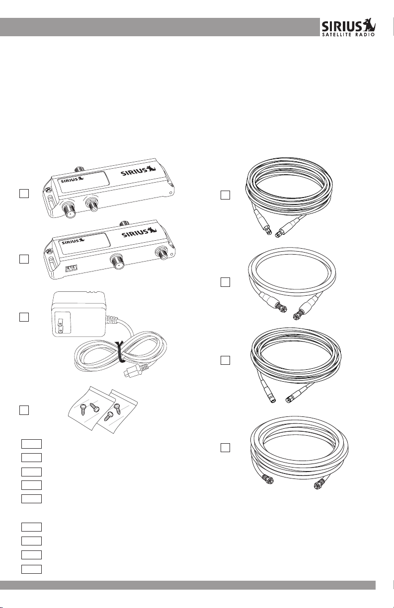
Box Contents
Unpack your SIRIUS/DBS Signal Combiner/Splitter and be sure that everything
shown below is present. If anything is missing or damaged, or if your SIRIUS/
DBS Signal Combiner/Splitter fails to operate properly, notify the dealer or retailer
where you purchased the product immediately. It is recommended that you retain
the original receipt, carton, and packing materials in case you need to return or
ship your SIRIUS/DBS Signal Combiner/Splitter in the future.
SR-100C
SIRIUS/DBS Signal Combiner System
SR-2260 Combiner-Outdoor
A
B
C
Made in China
DBS IN
SR-100C
SIRIUS/DBS Signal Combiner System
SR-2250 Splitter-Indoor
Made in China
DC IN
SIRIUS IN
E
SIRIUS OUT
DBS OUT
F
D
A
Signal Combiner (SR-2260)
B
Signal Splitter (SR-2250)
Power Supply
C
D
Mounting Screws (4)
E
30 ft. RG-58, SMA to SMA Connector, SIRIUS Outdoor Antenna to
Signal Combiner Cable
F
3 ft. RG-6, F to F Connector, LNBF to Signal Combiner Cable
G
10 ft. RG-58, SMA to SMB Connector, Signal Splitter to SIRIUS Receiver Cable
H
10 ft. RG-6, F to F Connector, Signal Splitter to DBS Receiver/Tuner Cable
This Installation Manual (Not Shown)
SIRIUS/DBS Signal Combiner/Splitter Installation Guide
G
H
33
Page 4
Important Pre-Installation Notes
The notes in this section are important and vital to the successful installation of
the SIRIUS/DBS Signal Combiner/Splitter. Read this entire section carefully
before proceeding with the installation of the SIRIUS/DBS Signal Combiner/
Splitter.
Compatibility
While the SIRIUS/DBS Signal Combiner/Splitter is compatible with most DISH
Network and DIRECTV systems, there are several instances in which a particular
configuration may not be compatible with the SIRIUS/DBS Signal Combiner/
Splitter. The following two sections discuss certain incompatibilities with Dish
Network configurations and DIRECTV configurations. Read the section for your
particular system.
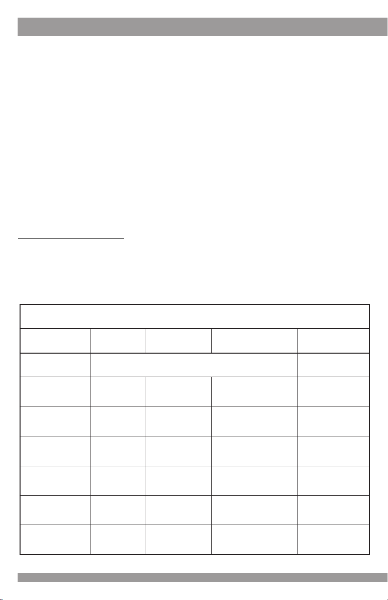
DISH Network Systems
The incompatibilities for DISH Network systems fall into several categories,
namely, configurations using a Legacy model LNBF, configurations using Legacy
model receivers/tuners, and configurations receiving three orbital locations. The
following compatibility chart shows compatible configurations, and the sections
following discuss in detail certain incompatibilities.
trahCytilibitapmoCsmetsySkrowteNHSID
foepyT
FBNL
ycageLrettamt'nseoDoN
orPhsiD2oN
orPhsiD2
sulPorPhsiD2oN
s'orPhsiDowT3
&orPhsiD
sulPorPhsiD
&hsiD
repuS
orPhsiD
4
rebmuN
sFBNLfo
3oN
444PD,seY
hctiwsitluM
?tneserP
seY
43PDro12PD
seY
43PDro12PD
hsiD-
SIRIUS/DBS Signal Combiner/Splitter Installation Guide
/revieceR
epyTrenuT
orPhsiD-
sulPorPhsiD-
retpadA/wycageL-
orPhsiD-
sulPorP
retpadA/wycageL-
orPhsiD-
sulPorPhsiD-
retpadA/wycageL-
o
rPhsiD-
sulPorPhsiD-
retpadA/wycageL-
orPhsiD-
sulPorPhsiD-
retpadA/wycageL-
orPhsiD-
sulPorPhsiD-
retpadA/wycageL-
?elbitapmoC
seY
seY
seY
oN
oN
seY
Page 5

DISH Network Legacy Model LNBF
There are three models of LNBFs which are found in DISH Network systems:
• Dish Pro LNBF
• Dish Pro Plus LNBF
LNBF
• Legacy LNBF
Of these three models, the Legacy LNBF is not compatible
with the SIRIUS/DBS Signal Combiner/Splitter. To determine
which model of LNBF your DISH Network system is using,
examine the satellite dish or the LNBF located on the satellite
dish. If the designation “Dish Pro” or “Dish Pro Plus”, or
the corresponding logo (shown to the right), are not found
on the satellite dish or on the LNBF, then your DISH
Network system is using a Legacy LNBF which will not work with the SIRIUS/DBS
Signal Combiner/Splitter.
DISH Network Legacy Model Receivers/Tuners
The SIRIUS/DBS Signal Combiner/Splitter is compatible with the following DISH
Network receivers/tuners:
• Dish Pro Single Receiver/Tuner
• Dish Pro Plus Dual Receiver/Tuner
• Legacy Receiver/Tuner with a DishPro Adapter
If your configuration is using a Legacy receiver/tuner, check to be sure it has a
DishPro adapter connected to it. If it does, then the SIRIUS/DBS Signal
Combiner/Splitter will work with the Legacy receiver/tuner, provided that the
SIRIUS/DBS Signal Combiner and/or Splitter is not
installed between the Legacy receiver/tuner and the
DishPro adapter.
A Legacy receiver/tuner which does not have a
DishPro adapter connected is not compatible with the
SIRIUS/DBS Signal Combiner/Splitter. However, if you
DishPro Adapter
DishPro Adapter
Enables non-DishPro receivers
to function with DishPro
switches and LNBF's
have a configuration which uses multiple receivers/
tuners, remember that the ‘Dish Pro Single’ and ‘Dish
Pro Plus Dual’ receivers/tuners are compatible. Install the SIRIUS/DBS Signal
Combiner/Splitter in the leg of your configuration with a compatible receiver/tuner,
and not in the leg with the incompatible Legacy receiver/tuner.
DISH Network Systems Receiving Three Orbital Locations
DISH Network systems which receive three orbital locations are not compatible
with the SIRIUS/DBS Signal Combiner/Splitter. Systems which receive one or two
orbital locations are compatible, as well as systems receiving four orbital locations
which use a “DP Plus 44” multiswitch.
SIRIUS/DBS Signal Combiner/Splitter Installation Guide
55
Page 6

DIRECTV Systems
ONE
ORBITAL
LOCATION
TWO
ORBITAL
LOCATIONS
THREE
ORBITAL
LOCATIONS
FOUR
ORBITAL
LOCATIONS
RECVR/TUNER
RECVR/TUNER
DP21/DP34
MULTI-
SWITCH
DP PLUS 44
MULTISWITCH
The incompatibilities for DIRECTV systems are limited to two categories, namely,
configurations using three LNBFs with a multiswitch which is not powered
externally, and configurations using three LNBFs with a multiswitch co-located
with the LNBFs at the satellite dish. The following compatibility chart shows
compatible configurations, and the sections following discuss in detail certain
incompatibilities.
trahCytilibitapmoCsmetsySVTCERID
sFBNLforebmuN?tneserPhctiwsitluM?elbitapmoC
1oNseY
2oNseY
2seYseY
3oNoN
3
,seYtuohtiwylppuSrewoPlanretxe
sFBNLhtiwdetacol-ocro
hsidetilletasta
oN
3,seYhtiwylppuSrewoPlanretxeseY
6
SIRIUS/DBS Signal Combiner/Splitter Installation Guide
Page 7

DIRECTV with Three LNBFs with External Multiswitch
If your configuration uses three LNBFs, and has a multiswitch, the multiswitch
must be externally powered to be compatible with the
SIRIUS/DBS Signal Combiner/Splitter. Externally powered
means that the multiswitch is connected to an AC outlet.
LNBFs
Examine your multiswitch to determine if it is connected
to an AC outlet. There should also be a label on the
multiswitch which specifies the external power
requirements, if it is externally powered. If the multiswitch is
not externally powered, your configuration will not work with
the SIRIUS/DBS Signal Combiner/Splitter.
DIRECTV with Three LNBFs with Co-Located Multiswitch
If your configuration uses three LNBFs which have a multiswitch co-located with
the LNBFs at the satellite dish, it is not compatible with the SIRIUS/DBS Signal
Combiner/Splitter.
Cable Length
When the SIRIUS and DBS signals are combined together in one RG-6 cable, the
maximum length of the cable should not exceed 200 feet.
Multiswitches, Signal Splitters, DishPro Adapters
If your satellite TV configuration is using multiswitches, signal splitters, DishPro
adapters (DISH Network), or other device, all these devices will prevent the
SIRIUS signal from passing through them, therefore the SIRIUS signal cannot be
combined with the satellite TV signal when passing through these devices.
Instead, the SIRIUS signal and satellite TV signal have to be both combined and
split either
before
or
after
these devices.
Stated in the simplest terms, between the SIRIUS/DBS Combiner and the SIRIUS/
DBS Splitter, there can only be an uninterrupted length of RG-6 cable.
CORRECT
INCORRECT
SIRIUS/DBS
COMBINER
SIRIUS/DBS
SPLITTER
SIRIUS/DBS Signal Combiner/Splitter Installation Guide
SIRIUS/DBS
COMBINER
MULTISWITCH
SIRIUS/DBS
SPLITTER
SIRIUS/DBS
COMBINER
SPLITTER
SIRIUS/DBS
SPLITTER
SIRIUS/DBS
COMBINER
DISHPRO
ADAPTER
SIRIUS/DBS
SPLITTER
77
Page 8

Configuration Considerations
R
There are differing configurations which may be found in satellite TV systems.
You should determine your overall configuration, and where you will be installing
the SIRIUS/DBS Signal Combiner/Splitter in
your configuration before proceeding with the
installation. Generally, you’ll want to install it
nearest to the receiver/tuner where you will be
using your SIRIUS receiver.
A simple configuration using the SIRIUS/DBS
Signal Splitter/Combiner might look like the
illustration shown to the right.
Other installations (shown below and on the
next page) all follow the same guideline, that
there cannot be any device between the
SIRIUS/DBS Combiner and the Splitter. Refer
to these illustrations to determine where you
will install the SIRIUS/DBS Signal Splitter/
Combiner in your system.
IRD
COMBINER
SPLITTER
SIRIUS
RECEIVE
RECVR/TUNER
SIRIUS
RECEIVER
8
COMBINER
SPLITTER
MULTISWITCH
RECVR/TUNERs
COMBINER
SPLITTER
MULTISWITCH
SIRIUS
RECEIVER
SIRIUS/DBS Signal Combiner/Splitter Installation Guide
RECVR/TUNERs
Page 9

RECVR/TUNER
COMBINER
SPLITTER
MULTISWITCH
DISH NETWORK ONLY:
COMBINER
SPLITTER
DISHPRO
LEGACY
RECVR/TUNER
ADAPTER
MULTISWITCH
SIRIUS
RECEIVER
RECVR/TUNERs RECVR/TUNERs
SIRIUS
RECEIVER
Installation Procedure
Once you have determined where in your system you will be mounting the
SIRIUS/DBS Signal Combiner/Splitter, you can proceed with the installation. If
you have not yet mounted your SIRIUS outdoor antenna, do that first, carefully
following the installation instructions included with the outdoor antenna. For ease
of installation, mount the outdoor antenna on the support bracket for the satellite
TV dish as shown in the antenna installation instructions, however, the SIRIUS
antenna may be mounted anywhere within 30 feet of the satellite TV dish.
Once the SIRIUS outdoor antenna has been mounted, follow these steps to install
the SIRIUS/DBS Signal Combiner/Splitter.
Outdoors:
1. Install the Signal Combiner (shown as A on page 3) in a convenient location
within 3 feet of the satellite TV dish using the provided screws.
2. Disconnect the cable which brings the signal from the
satellite TV dish and connect that cable to the Signal
Combiner connector labeled COMBINED OUT.
Depending upon where you are installing the SIRIUS/
DBS Signal Combiner/Splitter in your system, this cable
may be connected to the LNBF at the satellite dish, or
connected to a multiswitch, or connected to a signal
splitter, etc. When disconnecting this cable, make a note
of where it was connected for the next installation step.
COMBINED OUT
COMBINER
DBS IN SIRIUS IN
SIRIUS/DBS Signal Combiner/Splitter Installation Guide
99
Page 10

3. Connect one end of the 3 ft. RG-6 cable (shown as F on page 3) to the device
from which the cable in Step 2 was disconnected (i.e., the satellite dish LNBF, or
the multiswitch, or the signal splitter, etc.).
4. Connect the other end of cable F
to the Signal Combiner connector
labeled DBS IN. When connected,
be sure to slide the rubber boots
CABLE "E" CABLE "F"
on each end of the cable over the
connections to protect the
COMBINER
"A"
connections from the weather
elements.
5. Connect one end of the 30 ft. RG58 cable (shown as E on page 3)
to the SIRIUS outdoor antenna.
"C"
SATELLITE
TV CABLE
SPLITTER
EXISTING
"B"
6. Connect the other end of cable E
to the Signal Combiner connector
labeled SIRIUS IN. When
CABLE "H" CABLE "G"
RECVR/TUNER
SIRIUS
RECEIVER
connected, be sure to slide the
rubber boots on each end of the
cable over the connections to protect the connections from the weather elements.
Indoors:
1. Install the Signal Splitter (shown as B on page 3) near to where the cable which
brings the signal from the satellite TV dish terminates. Use the provided screws
for mounting.
2. Disconnect the cable which brings the signal from the satellite TV dish from the
device that it is connected to (i.e., a Receiver/Tuner, or a Multiswitch, or a
DishPro Adapter, etc.), and connect this cable to the Signal Splitter connector
labeled COMBINED IN. When disconnecting this cable,
make a note of where it was connected for the next
COMBINED IN
installation step.
3. Connect one end of the 10 ft. RG-6 cable (shown as H on
page 3) to the device from which the cable in Step 2 was
SPLITTER
disconnected (i.e., the Receiver/Tuner, or the Multiswitch,
or the DishPro Adapter, etc.).
4. Connect the other end of cable H to the Signal Splitter
POWER
DBS
SIRIUS
OUT
IN
OUT
connector labeled DBS OUT.
5. Connect one end of the 10 ft. RG-58 cable (shown as G on page 3) to the Signal
Splitter connector labeled SIRIUS OUT.
6. Connect the other end of cable G to your SIRIUS receiver.
10
SIRIUS/DBS Signal Combiner/Splitter Installation Guide
Page 11

7. Connect the Power Supply (shown as C on page 3) to the Signal Splitter, and
plug the Power Supply in a working AC outlet.
This completes the installation of the SIRIUS/DBS Signal Combiner/Splitter.
Power on your SIRIUS receiver and satellite TV system to verify that they are
working correctly and that the installation was successful.
Troubleshooting
If the SIRIUS receiver displays the message “ANTENNA NOT DETECTED”, the
first thing to do is to verify that you have installed the SIRIUS/DBS Signal
Combiner and Splitter correctly.
1. Follow the step-by-step installation instructions again, verifying each connection
and cable type, and checking that the cable connectors are screwed on tight.
2. Is there any device such as a Multiswitch, Splitter, DishPro Adapter, etc.,
between the SIRIUS/DBS Signal Combiner and Splitter? If so, you have installed
the SIRIUS/DBS Signal Combiner and Splitter incorrectly. These devices prevent
the SIRIUS signal from passing through. Consult the illustrations on pages 7, 8,
and 9 for proper installation, and reinstall the SIRIUS/DBS Signal Combiner/
Splitter
3. Verify that the Power Supply for the SIRIUS Splitter connected to the SIRIUS
Splitter, and is plugged into a working AC outlet.
If the SIRIUS receiver displays the message “ACQUIRING SIGNAL”, then the
SIRIUS signal is weak.
1. Review the installation instructions included with the SIRIUS outdoor antenna and
be sure that the outdoor antenna is installed properly, and aimed in the correct
direction, as explained in the installation instructions for the outdoor antenna.
2. It may be necessary to temporarily connect the SIRIUS receiver directly to the
outdoor antenna to verify that the outdoor antenna is receiving a good SIRIUS
signal. Use the “Antenna Aiming” or “Signal Indicator” feature in your SIRIUS
receiver to aim the antenna properly. Consult the user guide which came with
your SIRIUS receiver for further information on using this feature.
If you are still unable to resolve the problem, contact your dealer or retailer where
you purchased the product, or SIRIUS product support for more help.
SIRIUS Product Support: 1-800-869-5590
customercare@sirius-radio.com
SIRIUS/DBS Signal Combiner/Splitter Installation Guide
1111
Page 12

Specifications
Combiner & Splitter Dimensions (LxWxH) ......................... 120mm x 59mm x 23mm
4.72” x 2.32” x 0.91”
Combiner Weight .........................................................................0.144 kg, 5.08 oz
Splitter Weight .............................................................................0.146 kg, 5.15 oz
Frequency Range (SIRIUS) ................................................. 2320.0 to 2332.5 MHz
Frequency Range (DBS) ............................................................. 950 to 2150 MHz
Power Input ................................................................................. 20 VDC, 800 mA
Maximum Cable Run (Between Combiner and Splitter)...................... 200 ft. RG-6
Operating Temperature ............................................... -40C to +85C, -40F to 185F
Operating Humidity ............................................... 5% to 95% RH (Rain Resistant)
© 2005 SIRIUS Satellite Radio Inc.
SIRIUS Satellite Radio
1221 Avenue of the Americas
New York, NY 10020
(888) 539-7474
www.sirius.com
SIRIUS/DBS-Signal-Combiner/Splitter-Install-Manual (v012605)
 Loading...