

Page 1
I N S T A L L A T I O N
I N S T R U C T I O N S
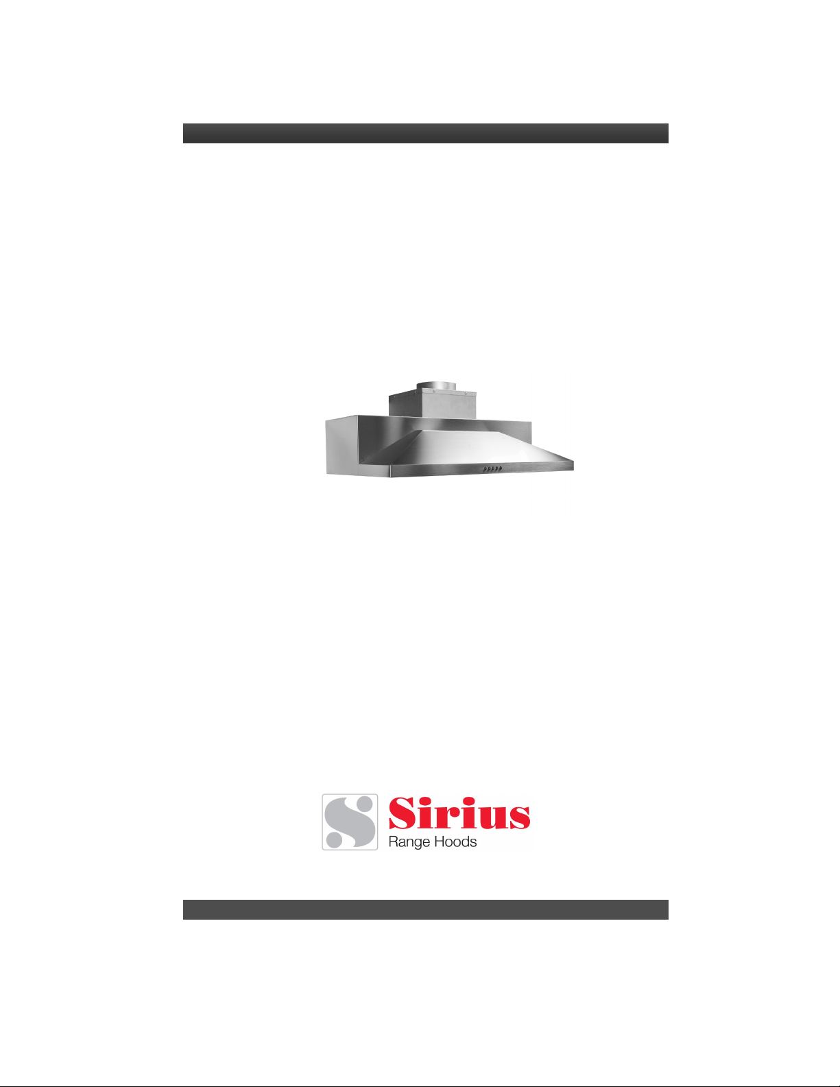
CARE AND USE MANUAL FOR:
UNDER CABINET RANGE HOODS
Model covered by these instructions:
SUF1
* * * B E F O R E I N S T A L L A T I O N * * *
ENSURE THERE IS NO VISIBLE OR HIDDEN DAMAGE SUSTAINED
DURING SHIPPING
* * * S H I P P I N G D A M A G E * * *
MUST BE REPORTED WITHIN 5 DAYS OF RECEIPT
Telephone (Toll Free): 866.528.4987 Fax (Toll Free): 866.365.9204
www.siriushoods.com [email protected]
Page 2
W A R N I N G S
Thank you for purchasing a Sirius Range Hood. Please read all the
instructions in this manual before installing the appliance.
Save these instructions for future reference.
The appliance is not intended for use by young children or infirm persons without supervision.
Young children should be supervised to ensure they do not play with the appliance. If the
range hood is vented, the air so vented must be ducted into a dedicated duct that
with any other equipment whatsoever. All ducting must conform to all requirements of the local
authority.
If the range hood is to be used inside he same structure (home or building) as any equipment
hat burns combustible material such as oil, coal, gas, etc. then pervision must be made for
make up air. Under certain circumstances, the range hood could create a negative air pressure
inside the structure. This negative air pressure must not exceed 0.04 mbar (please consult
your local HVAC professional for guidance at this point).
The use of combustible material in close proximity of the range hood must be avoided. When
frying, please pay particular attention to fire risk due to grease. Being highly inflammable,
fried oil is especially dangerous. In order to avoid possible fire risk, all instructions for greasefilter cleaning and for removing eventual grease deposits must be followed strictly.
is not showed
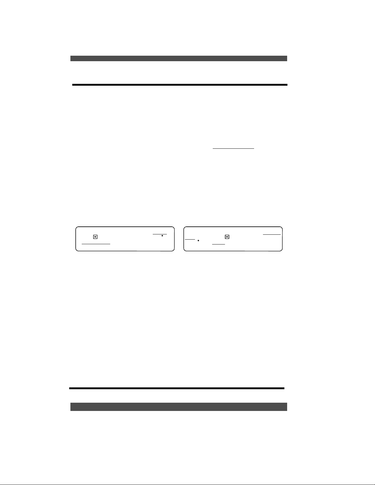
If the rating label in the cooker-hood shows the
symbol , the appliance is built in class II and
it does not need
Only use this appliance as an exhaust ventilation system for the removal of cooking vapors.
use to expel flammable substances or any other materials or vapors.
NOT
The installation procedures in this manual are intended for qualified installers, service technicians or persons with similar qualified background.
yourself.
When performing the electrical connections on the appliance, please ensure that the current
supply is provide with ground connection and that the voltage values correspond to those
indicated on the label placed inside the appliance itself.
Ensure that electrical power is turned off at source before commencing installation. All electrical wiring must be properly installed, insulated and grounded and conform to all applicable
codes and standards.
Make sure all existing ductwork is clean of grease build up, or ductwork should be replaced, if
necessary, to avoid the possibility of a grease fire. Check all joints on ductwork to ensure
proper connection and all joints should be properly taped. Be careful when cutting through
ceilings or walls not to damage any hidden pipes or electrical wiring. Ensure your kitchen has
sufficient air return vents to replace the exhausted air.
any ground connection.
If the rating label in the cooker-hood does not
show the symbol ,the appliance is built in
class I and it needs
DO NOT attempt to install this appliance
the ground connection.
DO
Page 3

TABLE OF CONTENTS
BEFORE YOU BEGIN 1
DUCTING 1
External Venting Requirements 1
Duct Run Calculation 2
ELECTRICAL 2
Electrical Supply 2
INSTALLATION 3
Connecting Electricity and Ducting 3
Re-Circulating Requirements 4
OPERATING PROCEDURES 5
General Advice 5
Functions 5
MAINTENANCE 6
Cleaning the Filter 6
Cleaning the Hood 6
Light Bulb Replacement 6
WARRANTY 7
Page 4
B E F O R E Y O U B E G I N
The manufacturer declines all
responsibility in the event of failure
to observe the instructions given
here for installation, maintenance
and suitable operation of the
product. The manufacturer further
declines all responsibility for injury
due to negligence and the warranty
of the unit automatically expires due
to improper maintenance and/or
installation.
Please read this entire manual and
ensure that you are fully conversant
with the requirements and limitations
D U C T I N G
BEFORE YOU BEGIN:
It is advisable to test run the
range hood before installation.
(Not applicable if the range hood is
used in re-circulating mode)
WARNING: Do not vent this
appliance into any other ductwork,
spaces between walls, ceilings,
attics, garages or any other confined
space.
External Venting Requirements
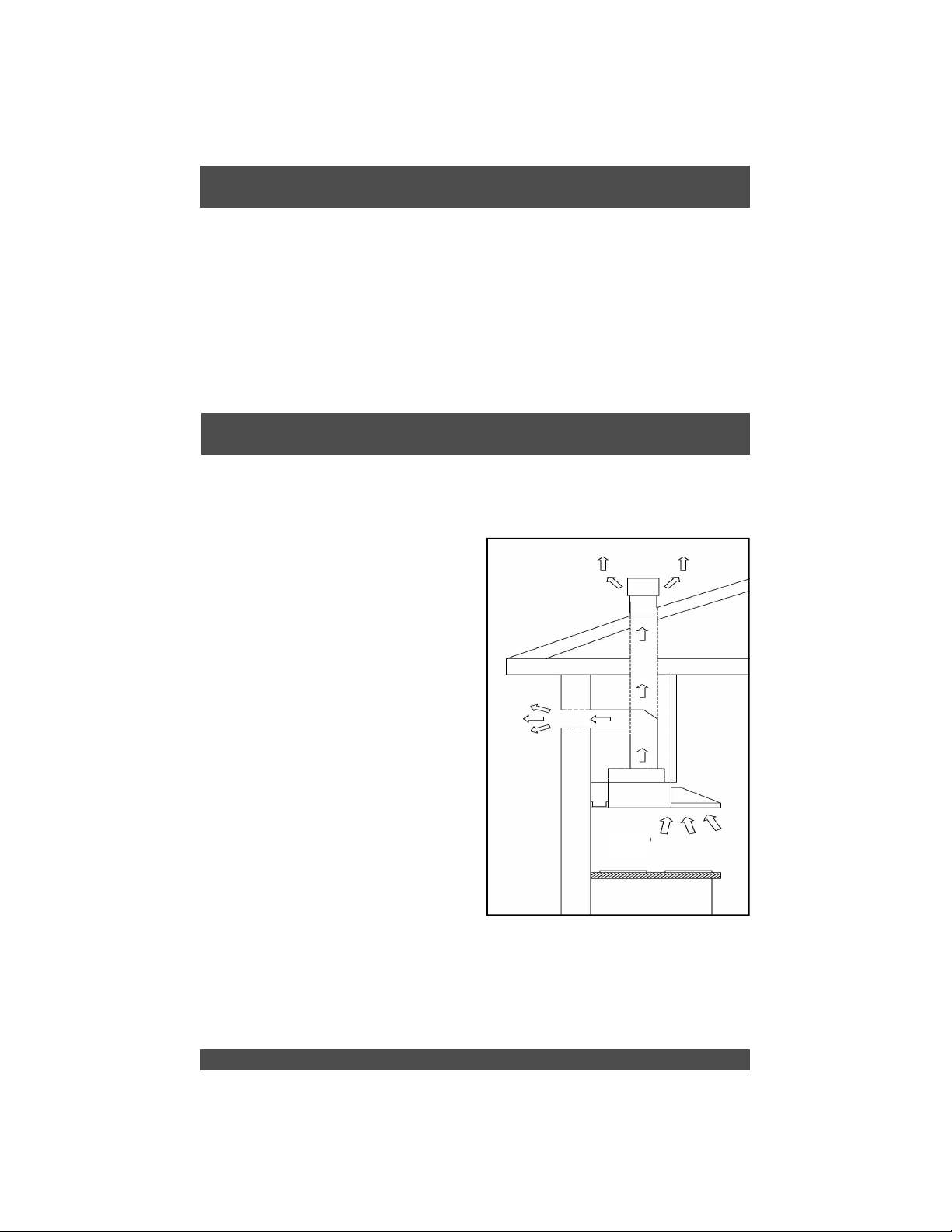
When planning new ductwork, always
look for the most direct route to the
outside. Venting can be done through
the roof or directly through the back
outside wall. (See Figure 1 )
Only use rigid type metal ducting
(plastic ducting is generally not permitted by code). Flexible ducting could
restrict airflow by up to 50%. Always
fasten connections with sheet metal
screws and tape all joints with certified
Silver Tape or Duct Tape.
screws to fasten ductwork to
the hood
will stop the dampers from opening
and your hood will not work. This
hood requires a 6” round duct outlet.
You can increase the duct size of the
duct run but never decrease it. Use
the shortest and most
1
, only use tape as the screws
Do not use
direc t route possible. Always,
wherever reduce the number of
transitions and turns with as few
sharp angles as possible.
Figure 1
Two staggered 45 degree angles are
better than one 90 degree. Make
these turns as far away from the
motor exhaust as possible, with as
much space between each bend.
Page 5
Duct Run Calculation
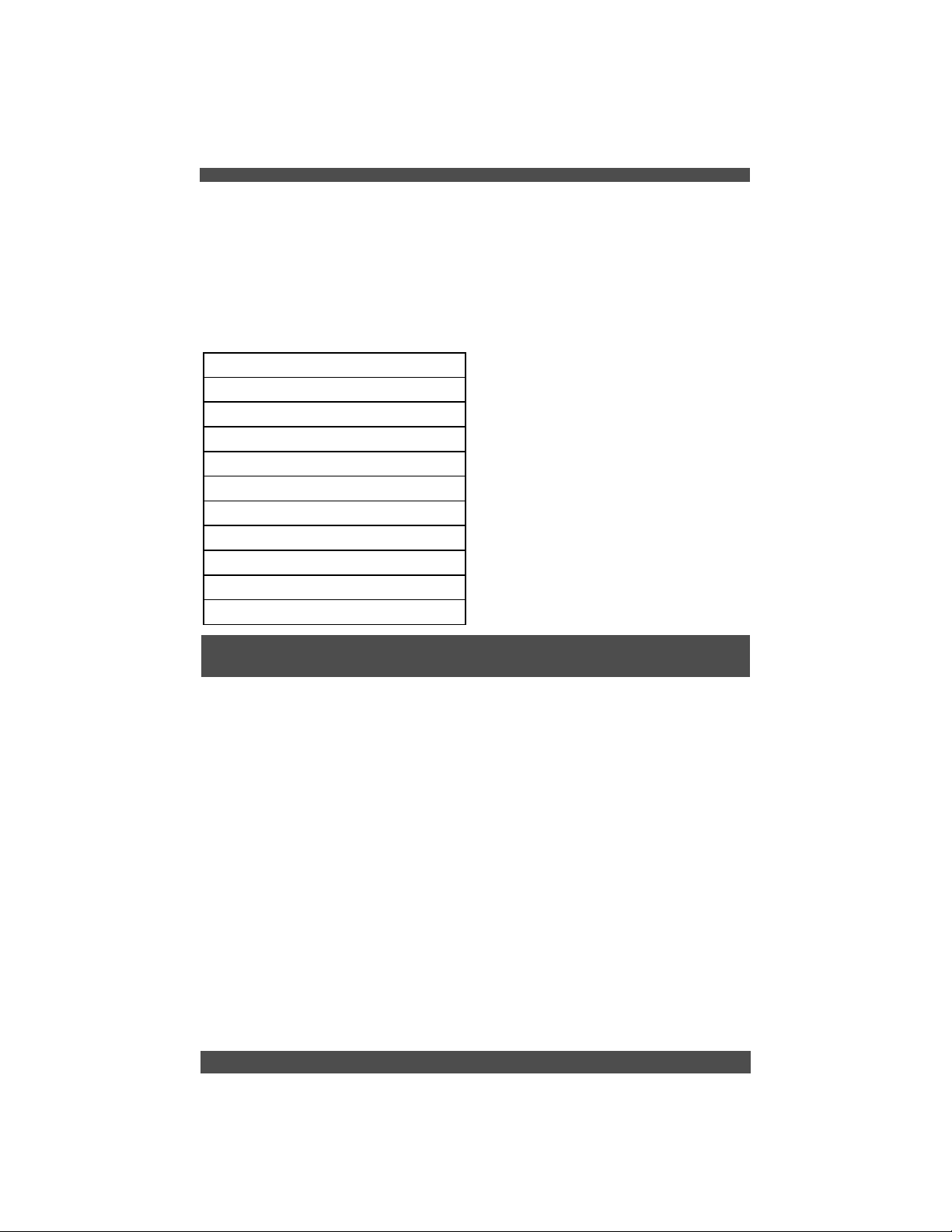
The maximum duct run before
effecting the performance of the
hood is 100’. Calculate your duct run
by measuring linear feet and adding
the elbows, transitions and caps
based on the table alongside.
Maximum Run
6” or 3 1/4 x 10” duct 100 FT
Deduct
Each 90 elbow used 15FT
Each 45 elbow used 9FT
Each 6” or 3 1/4 x 10” duct
Transition used 1FT
Each 3’1/4 x 10” to 6”
Transition used 5FT
Side Wall with damper 30FT
Roof Cap 30FT
The ducting connection to the hood
must be in line with the central
vertical axis of the range hood 1”
away from the back wall on which
the hood is to be mounted.
Range hoods may interrupt the
proper flow of combustion gases
from fireplaces, gas furnaces and
gas water heaters.
To minimize the risk of drawing
these lethal gases back into the
home, please follow the heating
equipment manufacturers safety
standards and guidelines carefully.
Refer to NFPA and ASHRAE for
additional information.
E L E C T R I C A L
WARNING: All electrical work must
be performed by a qu alified
electrician.
Please ensure that the appropriate
electrical codes or prevailing local
building codes and ordinances are
adhered to.
Ensure that the electricity supply is
disconnected at source. Do not use
an extension cord or adapter plug
with this appliance.
This appliance must be grounded.
Connect to a properly grounded
branch circuit, protected by a 15
amp circuit breaker.
Electrical Supply
This range hood requires a 120V,
60Hz supply and draws a maximum of
3 amps. The electrical supply to the
range hood should be at least 17”
from the underside of the installed
range hood.
For a typical installation, where the
underside of the range hood will be
30” above the counter top and the
counter top is 36” above the floor
level, the electrical supply should be
76”” above floor level and no further
than 3” to the right (as you face the
wall) of the central axis of the range
hood.
2
Page 6
I N S T A L L A T I O N
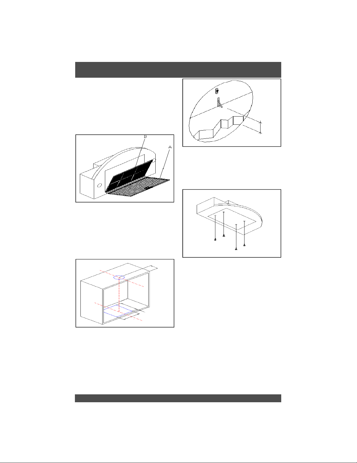
Before installing the appliance, in
order not to damage the appliance
itself, the metal grease filter should
be removed by pushing the special
filter handle toward the back side of
the cooker hood and turning it
downwards so to unfasten it from its
slot (refer to figure 2A).
Figure 2
Make a cut-out on the bottom of the
cabinet to hold the appliance by using the drilling jig provided. This
opening must be 9.8” x 10.2” and at
a distance of 1” from the front edge
of the cabinet (refer to figure 3)
Min: 0.4”
Max: 1”
Figure 4
Insert the screws provided in the
holes inside the range hood (refer to
figure 6).
4
.
5
”
1
0
.
2
”
1
”
hood
he
t
f
o
Cent
er
Figure 3
”
8
.
9
To install the appliance adjust the
position of the stop side-springs
using the appropriate screws,
according to the thickness of the
board. The base of the cabinet must
be from 0.4” to 1” thick (refer to
figure 4).
3
Figure 5
Insert the built-in unit in the hole
made in the cabinet until the stop
click of the side-springs is heard and
the hood is temporary held in
position.
Connecting Electricity and
Ducting
Please refer to the Electrical Supply
section on page 2 for the required
location of the electrical supply.
CAUTION: Make sure the power is
turned off at source. Make electrical
connections (refer to Figure 8).
Page 7
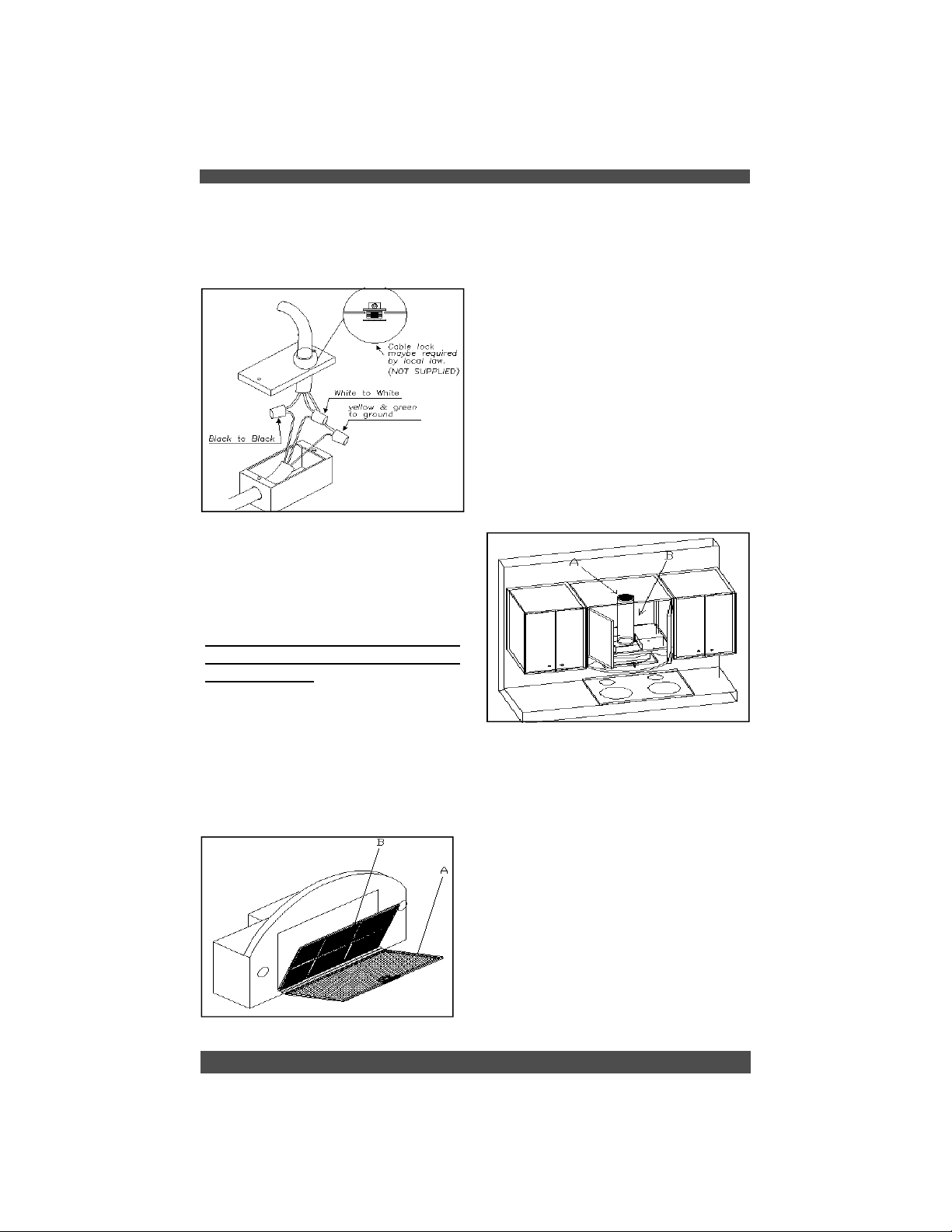
Ensure that the plastic flaps at the
exhaust outlet for the fan move
freely and have not become jammed
or stuck.
Figure 6
Connect the appropriate length of
ducting to the fan exhaust point and
join up with the ducting to the exterior.
Do not fix the ducting to the range
hood exhaust outlet with screws use duct tape. Use duct tape on all
joints.
The carbon filter fits in behind the
aluminium grease filter. Ensure that
the plastic tabs on the carbon filter
are facing outwards otherwise it will
be difficult to remove it later for
replacement.
A short length of ductwork must
be connected from the exhaust
outlet on the fan to wherever the
air is to be exhausted (refer to
figure 8 A and B)
Allow sufficient
space to connect the ductwork to the
top of the exhaust outlet on the fan
housing.
Do not fix the ducting to
the range hood exhaust outlet with
screws, use duct tape. Duct tape
should be used on all joints.
Re-Circulating Requirements
Figure 8
If the unit is to be used in the
re-circulating mode, fit the carbon
filter after the installation is complete
(refer to Figure 7B).
Figure 7
4
Page 8
O P E R A T I N G P R O C E D U R E S
Read all the instructions before
operating the appliance.
Save these instructions for future
reference.
DO NOT USE WATER including wet
dishcloths or towels, as a violent
steam explosion may occur.
Functions
General Advice
Ensure that the grease filters are in
place. Without these components,
operating blowers could catch on to
hair, fingers and loose clothing.
Keep fan, filters and surfaces clean
of grease and fat. Always turn hood
fan ON when cooking. NEVER leave
cooking unattended.
NEVER dispose cigarette ashes,
ignitable substances or any foreign
objects into blowers.
Cooking that generates flame is not
recommended as this hood is
equipped with a thermal overload
that will shut down the motor if it
senses excessive heat. When
frying, oil in the pan can easily
overheat and ignite. Heat oil slowly
in an appropriately sized pot
(covering the entire burner) to
reduce the risk of boiling over and
burning
In the event of a range top grease
fire, observe the following:
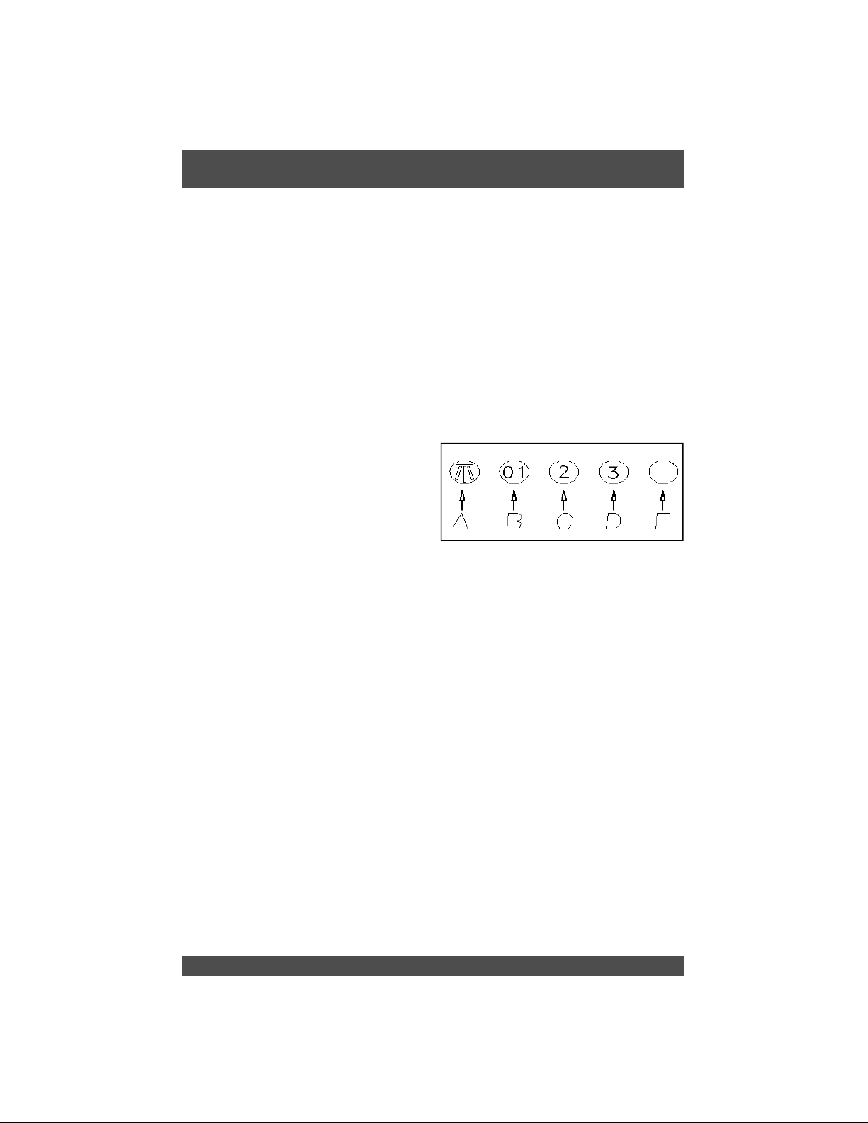
Under Cabinet Controls
A: Light ON/OFF button
B: Blower Speed 1 (low) or OFF
C: Blower Speed 2 (medium)
D: Blower Speed 3 (high)
E: Hood in Operation Light
Generally, the grease filter should
be washed on a regular basis to
avoid grease filter fires.
The blower should be turned on for
approximately 5 minutes before
cooking in order to establish air
currents upward through the hood.
Use the low speeds for normal use
and the higher speeds for strong
odors and fumes.
Switch OFF the range hood. Turn
off the cook top then
with a close fitting lid, cookie sheet
or other metal tray. If the flames do
not go out immediately.
EVACUATE AND CALL THE FIRE
DEPARTMENT. Never pick up a
flaming pan – you may be burned.
5
smother flames
Page 9
M A I N T E N A N C E
The range hood should provide
many years of trouble free use
provided it is properly maintained.
Be sure the lights are cool before
cleaning the hood – they are
halogen and become extremely hot.
Cleaning the Filter
The aluminium mesh filters should
be washed by hand or in the
dishwasher as required. Damaged
and worn filters must be replaced
immediately. (Do not operate blower
when filters have been removed).
Allow filters to dry before replacing
them, otherwise water will be drawn
into the blower.
If a carbon filter has been fitted, this
must be replaced every 6 months as
a minimum, depending on usage
and type of cooking that is
performed.
It is suggested that a spare set of
carbon filters is kept on hand.
These can be ordered from the
supplier of your range hood.
Cleaning the Hood
The outside and interior of your hood
should be wiped regularly with a
cl ean, damp c loth an d m ild
househol d dish d ete rgent o r
degreaser.
to react on the surface for a few
minutes and then wipe with a clean
dry cloth.
On the surfaces that are exposed
directly to heat from the cook-top, it
is advisable to clean these regularly
to avoid the deposits from becoming
baked on.
Do not use abrasive cleaning agents
as these will destroy the brushed
finish.
Light Bulb Replacement
(If in doubt, call 866.528.4987)
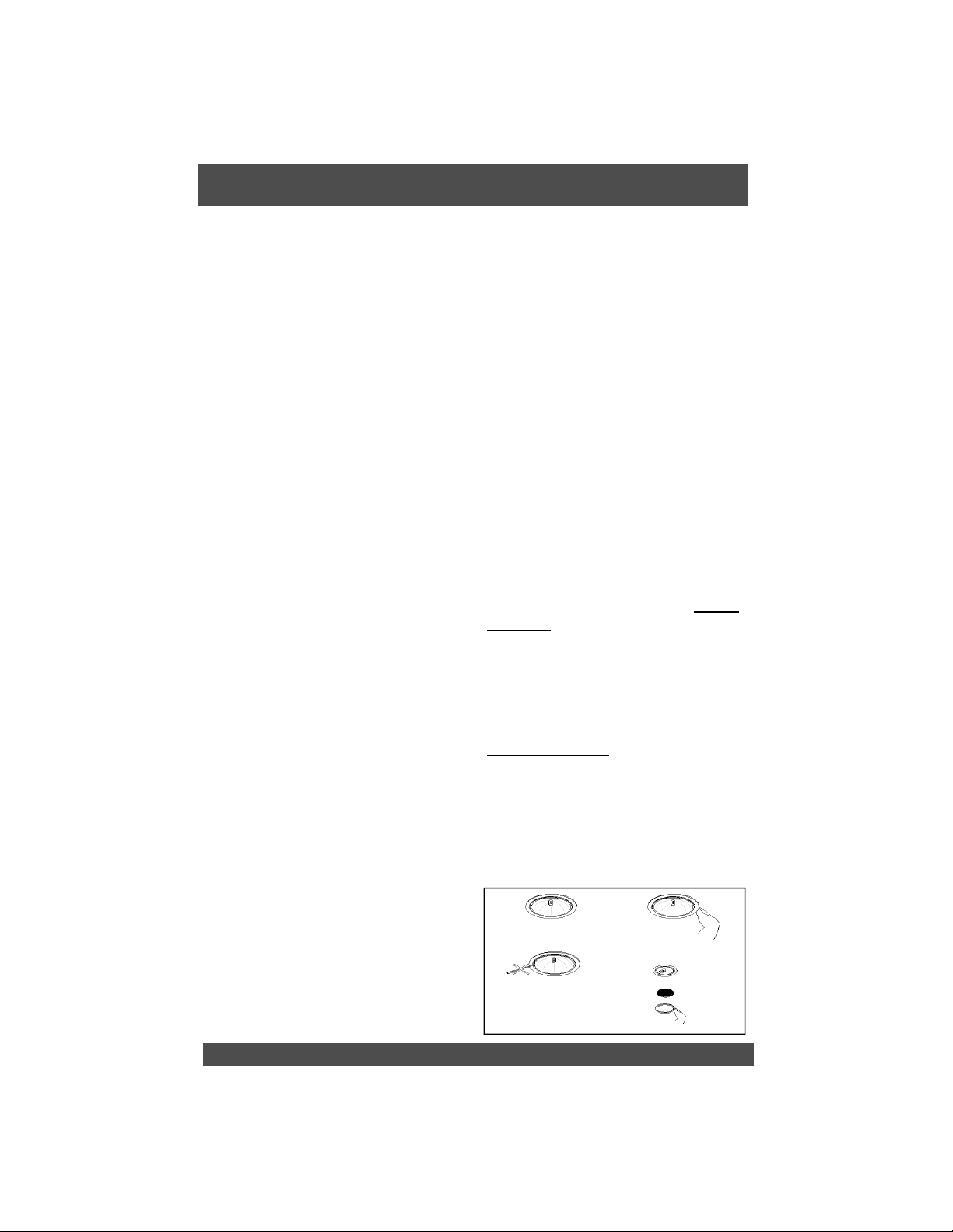
Turn blower and lights off. Make
sure the lights are cool. If new lights
do not operate, check fuses and be
sure globes and breakers are inserted correctly. Remove the
blocking ring by prying out with a
sharp, soft instrument such as a
toothpick. (refer to Figure 10) Steel
instruments will scratch the surface.
Be careful that the glass does not
fall out and break.
Do not remove the entire fixture
(socket) as this is very difficult to
reinstall. Replace the appropriate
bulb. Check parts brochure or specification sheets on our website. Wipe
both sides of the glass whilst it is
out. Re-insert the glass-blocking
ring and fasten it.
glass-
Use a good quality non-abrasive
foaming type stainless steel cleaner
for exterior surfaces.
Follow the manufacturers directions.
Generally the foam is sprayed onto a
clean dry cloth and then applied to
the stainless steel. Allow the foam
Figure 10
6
Page 10

T h r e e Y e a r L i m i t e d W a r r a n t y
WARRANTY SERVICE
To qualify for warranty service, you must notify Sirius Range Hoods at the
address stated below or call toll free USA or Canada
provide the model number, description of the fault or defect and original date of
purchase. Sirius reserves the right to request proof of original purchase.
will at its sole option and discretion replace products that arrive damaged
through shipping, provided shipping damage is reported as stated above
within 5 business days of receipt of the shipped product or products.
ONE YEAR SERVICE REPAIR WARRANTY:
During the first year from date of original purchase, Sirius will, at its option,
repair or replace, without charge, any product or part which is found to be
defective under normal use and service.
THREE YEAR PARTS WARRANTY:
For three years from date of purchase, Sirius will provide free of charge,
non-consumable replacement parts which are found to be defective under
normal use and service.
WHO IS COVERED:
Sirius Range Hoods warrants to the original consumer purchaser of its products
that such products will be free from defects in materials and workmanship for a
period of three years from the original date of purchase. There are no other
warranties, express or implied, including, but not limited to, implied warranties of
merchantability or fitness for a particular purpose or application.
1-866-528-4987 and
Sirius
WHAT IS NOT COVERED:
This warranty does not extend to filters, lamps, batteries, ducts and ductwork
components. This warranty does not cover normal maintenance and service or
products or parts which have been subject to misuse, negligence, accident,
improper maintenance or repair, faulty installation or installation contrary to
recommended installation instructions. The warranty on glass screens is
limited to manufacturing defects only and expressly excludes cracks and
breakages as a result of faulty installation.
Labor and associated costs associated
directly with removal and re-installation are expressly excluded.
The duration of any implied warranty is limited to the three year period as
specified for the express warranty. Some states and provinces do not allow
limitation on how long an implied warranty lasts, so the above limitation may not
apply to you.
Canada: Sirius Range Hoods Ltd
1252 Speers Road Unit 11
Oakville, ON L6L 5N9
7 Register Online! www.siriushoods.com/warranty.htm
USA: Sirius Range Hoods Ltd
1051 Clinton Street
Buffalo, NY 14206
Page 11

Staple Invoice Here.
8
Page 12
USA: CANADA:
SIRIUS RANGE HOODS (USA) LTD. SIRIUS RANGE HOODS LTD.
1051 Clinton Street 1252 Speers Road Unit 11
Buffalo, NY 14206 Oakville, ON L6L 5N9
Telephone (Toll Free): 866.528.4987 Telephone: 905.257.0046
Fax (Toll Free): 866.365.9204 Fax: 905.847.0330
www.siriushoods.com Email: [email protected]
 Loading...