

Page 1

SIRIUS STRATUS
Satellite Radio Plug-n-Play Receiver
SV3TK1C User Guide
Page 2

Page 3

Congratulations on the Purchase of your new SIRIUS Stratus
SV3TK1C Plug-n-Play Receiver
Your new SI RI US Stratus SV3TK1C Plug-n- Play Receiver lets you enjoy SIR IUS® Satelli te
Radio’s digit al entertain ment in a ny vehicle where you’ve installed the included vehicle do cking stat ion.
The Stratus SV3TK1C is also compatible with the SUPH1C S IR IU S Universal Plug and
Play Home Kit, the SU PV1C SIR IUS Univers al P lug and Play Vehicle Kit, and the SU BX1C
SIRI US Plug and Play Universa l Boombox (each sold separately).
Use this manual to fam iliarize yourself with all of the Stratu s’ features and capabilities. For the
latest information abo ut this and other SIRI US produ cts and accessories, visit http://www.
siriuscanada.ca.
Page 4

Table of Contents
TABLE OF CONTENTS . . . . . . . . . . . . . . . . . . . . . . . . . . . . . . 2
WARNING AND SAFETY INF ORMATION . . . . . . . . . . . . . . . . . . . . .
IC Caution . . . . . . . . . . . . . . . . . . . . . . . . . . . . . . . . . . . 4
General Precautions . . . . . . . . . . . . . . . . . . . . . . . . . . . . . . . 4
COPYRIGHTS & TRAD EMARKS . . . . . . . . . . . . . . . . . . . . . . . . .
PACKAGE CONTENTS . . . . . . . . . . . . . . . . . . . . . . . . . . . . . .
INSTALLATION . . . . . . . . . . . . . . . . . . . . . . . . . . . . . . . .
Location . . . . . . . . . . . . . . . . . . . . . . . . . . . . . . . . . . . 10
Mounting the Receiver . . . . . . . . . . . . . . . . . . . . . . . . . . . . . 11
Installing the Antenna . . . . . . . . . . . . . . . . . . . . . . . . . . . . . 13
Connecting the Cigarette Lighter Adapter . . . . . . . . . . . . . . . . . . . . . 16
Maximizing Audio Quality From Your SI RI US Receiver . . . . . . . . . . . . . . . 16
Wireless Connection . . . . . . . . . . . . . . . . . . . . . . . . . . . . 16
Direct Connections . . . . . . . . . . . . . . . . . . . . . . . . . . . . . 17
Subscribing to the SIRIUS Service . . . . . . . . . . . . . . . . . . . . . . . . 20
CONTROLS . . . . . . . . . . . . . . . . . . . . . . . . . . . . . . . . .
SIRIUS Stratus SV3TK1C Reference Guide . . . . . . . . . . . . . . . . . . . . 22
SIRIUS Stratus SV3TK1C Docking Station Reference Guide . . . . . . . . . . . . . 23
OPERATION . . . . . . . . . . . . . . . . . . . . . . . . . . . . . . . . .
Display Screen Information . . . . . . . . . . . . . . . . . . . . . . . . . . . 24
Changing Channels and Categories . . . . . . . . . . . . . . . . . . . . . . . . 25
Selecting Channels Directly . . . . . . . . . . . . . . . . . . . . . . . . . . . 26
FM Frequency . . . . . . . . . . . . . . . . . . . . . . . . . . . . . . . . 27
Jump Button . . . . . . . . . . . . . . . . . . . . . . . . . . . . . . . . . 28
Channel Lock . . . . . . . . . . . . . . . . . . . . . . . . . . . . . . . . . 29
MEN U OPTIONS . . . . . . . . . . . . . . . . . . . . . . . . . . . . . . .
SIRIUS ID . . . . . . . . . . . . . . . . . . . . . . . . . . . . . . . . . . 30
FM Transmitter . . . . . . . . . . . . . . . . . . . . . . . . . . . . . . . . 31
Audio Level . . . . . . . . . . . . . . . . . . . . . . . . . . . . . . . . . 33
Tones . . . . . . . . . . . . . . . . . . . . . . . . . . . . . . . . . . . . 33
4
7
8
10
22
24
30
[ Table of Contents ]
2
Page 5

Clock . . . . . . . . . . . . . . . . . . . . . . . . . . . . . . . . . . . . 34
Jump Settings . . . . . . . . . . . . . . . . . . . . . . . . . . . . . . . . 35
Channel Lock . . . . . . . . . . . . . . . . . . . . . . . . . . . . . . . . . 36
Signal . . . . . . . . . . . . . . . . . . . . . . . . . . . . . . . . . . . . 39
Factory Default . . . . . . . . . . . . . . . . . . . . . . . . . . . . . . . . 39
TROUBLESHOOTIN G . . . . . . . . . . . . . . . . . . . . . . . . . . . . .
SPECIFICATIONS. . . . . . . . . . . . . . . . . . . . . . . . . . . . . . .
WARRANTY . . . . . . . . . . . . . . . . . . . . . . . . . . . . . . . . .
SIR IUS ID . . . . . . . . . . . . . . . . . . . . . . . . . . . . . . . . . .
41
42
43
44
[ Table of Contents ]
3
Page 6

Warning and Safety Information
IC Caution
“Operation is subject to the following two conditions: (1) thi s device may not cause interference, and (2) this dev ice must accept any interference, includ ing interference that may cause
undesired operation of the device.”
“To reduce potential radio interference to other users, the a ntenna type and its gain should
be so chosen that the equivalent iso tropically radiated power (EI RP) is not more than that
required for successfu l communication”.
“This device has been designed to op erate with an antenna having a maximum g ain of [2] dBi.
Antenna having a highe r gain is strictly prohibited per regula tions of Industry Canada. The
required antenna imped ance is 50 ohms.”
“To reduce potential radio interference to other users, the a ntenna type and its gain should
be so chosen that the equivalent iso tropically radiated power (e.i.r.p.) is not more than that
permitted for successf ul communication.”
This device and its antenna(s) must not be co-located or operating in conjun ction with any
other antenna or trans mitter.
General Precautions
Liqu id Cr ystal Prec autio ns
If the LCD screen on the receiver is damaged, do n ot to touch th e liquid crystal fluid. If any of
the following situatio ns happen, take the action indicated:
If the liquid crystal fluid comes in contact with your skin, wipe the skin area with a cloth
1.
and then wash the skin thoroughly with soap and running water.
If the liquid crystal fluid gets into your eye, flush the eye with clean water for at le ast 15
2.
minutes. Seek medical care.
[ Warning an d S afety Inf orm ati on ]
4
Page 7

If the liquid crystal fluid is ingested, flush y our mouth thoroughly with water. Drink large
3.
quantities of water an d induce vomiting. Seek medical care.
Safe ty Pre cautions
Be sure to observe the following warnings. Failure to follow t hese safety instructions a nd
warnings may result in a serious accident.
Do not operate the rec eiver in a way that might divert your at tention from driving s afel y.
•
As a driver, you alone are responsible for safely operating your vehicle in accordance with
traffic safety laws at all times.
Do not install the unit where it may obstruct yo ur view through the windshield, or of yo ur
•
vehicle’s indicator di splays.
Do not install the unit where it may hinder the function of s afet y devices such as an ai rbag.
•
Doing so may prevent t he airbag from functioning properly in t he event of an accident.
Be sure the unit is in stalled as described in th e installation in struction s which accomp any
•
each accessory kit. SI RIUS Satellite Radio is not responsible for issues arising fr om installations which were not inst alled according to the instructions .
To avoid short circui ts, do not open the unit, and never put or leave any metallic obje cts
•
(coins, tools, etc.) i nside the unit.
If the unit emits smok e or unusual odors, turn the power off i mmediately, and disconnect
•
the unit from any powe r source.
Do not drop the unit o r subject it to strong shocks.
•
If the unit doesn’t se em to be working properly, t urn the unit off, remove the battery fro m
•
the unit, wait 10 seco nds, replace the battery and then turn i t on again.
The installation and u se suggestions contained i n this manual are subject to an y restric -
•
tions or limitations that may be imposed by appl icable law. The purchaser should check
applicable law for any restrictions or limit atio ns before install ing and/o r operating this unit.
[ Warning an d S afety Inf orm ati on ]
5
Page 8

Oper ating Temperature
The receiver is designed to operate between -20° to +85° C (-4° to +185° F). Avoid leaving
the unit in a vehicle or elsewhere where the temperature may f all outside this range. Extreme
temperatures or extrem e temperature fluctuations can degrade t he performance of the LCD
display screen, and po ssibly damage it.
Clea ning and M aintenance
If the receiver become s dirty, turn the power off and wipe it clean with a soft cloth. Do not use
hard cloths, strong cl eaning fluids, paint thinner, alcohol, or other volatile solvents to clean.
These may cause damage to the unit.
[ Warning an d S afety Inf orm ati on ]
6
Page 9

Copyrights & Trademarks
© 2006 S IR IU S S atellite Radio Inc. All Rights Reserved.
® “S IR IU S”, the SIRIUS dog logo, channel names and logos are trademar ks of SI RIUS
Satellit e Radio Inc. “NF L” and the N FL Shield logo, and the N FL Sund ay Drive name and logo
are registered tradema rks of the National Football League. “NHL” and the NH L Sh ield are
registered trademarks of the National Hockey League. “NBA” and t he N BA silho uette logo are
registered trademarks of N BA Prope rties Inc. All other trademarks , service marks, sports team
names, album art, and logos are the property of their respecti ve owners. All Rights Reserved.
Portions of the software on this rec eiver are licensed under the eCos Licens e. Distribution of
eCos requires that the eCos source code be made available to S irius Satellite Radio cust omers. The eCos License and eCos sourc e code are available to the public at ht tp://www.sirius.
com/ecoslicense.
Sirius S atellite Radio reserves all rights to al l receiver software not covered under th e eCos
license. This includes all portions of receiver software that were not distr ibuted to Sirius as
part of the eCos opera ting system.
Hardware, subscription and activation fee required. For full Terms & Condit ions, visit
http://siriuscanada.ca . Prices and programming are subject to change. Not av ailable in H I and
AK. Equipment and subs cription sold separately. In stallation required with s ome equipment.
[ Cop yri ght s & Trad ema rks ]
7
Page 10
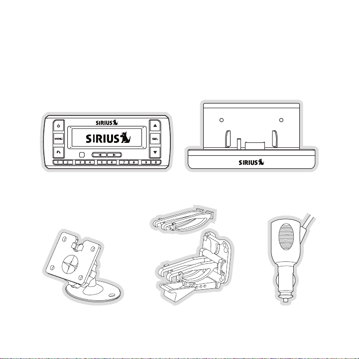
Package Contents
The following items are included with your purchase of the SIRIUS Stratus SV3TK1C receiver:
Strat us SV3T K1C Re ceiverStrat us SV3T K1C Re ceiver
Adhesi ve Dash MountAdhesi ve Dash Mount Vent Mo unt &
[ Pack age Co nte nts ]
8
Vent Mo unt &
Exten ded Vent Hooks
Exten ded Vent Hooks
Vehicle Dockin g Stati onVehicle Dockin g Stati on
Cigar ette Li ghter
Cigar ette Li ghter
Adapte r
Adapte r
Page 11
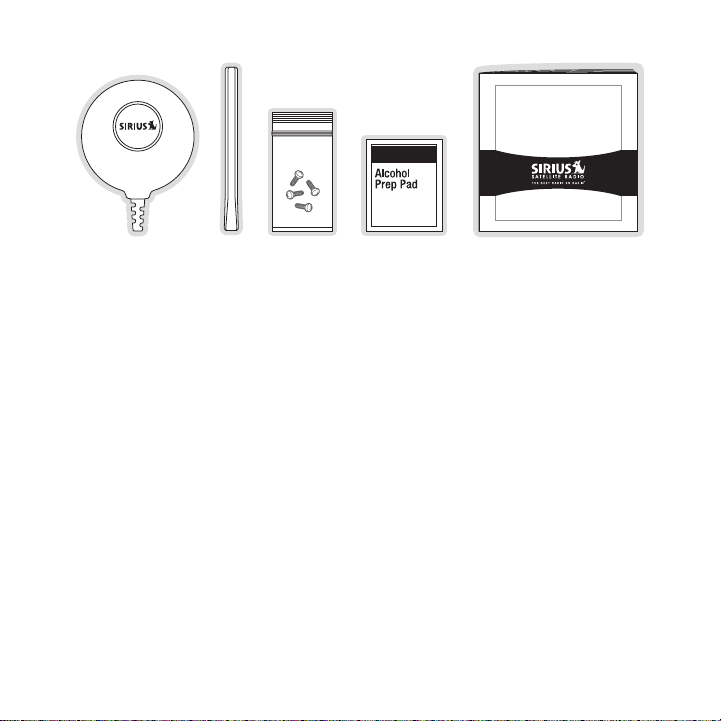
Satellite R adio Plug-n-P lay Receiver
SIRIUS STRATUS
SV3 U ser Gui de
Magne tic
Antenn a
Antenn a
Antenn a
Cover /Tail
Cover /Tail
Screw sScrew sMagne tic
Alcoho l
Alcoho l
Swab
Swab
User GuideUser Guide
Antenn a
Unpack your SIR IUS Stratus SV3TK1C recei ver carefully and make sure that everyth ing
shown is present. If a nything is missing or damaged, or if you r the receiver fails to operate,
notify your dealer imm ediately. It is recommended that you retain the origin al carton and packing materials in case you need to ship your receiver in the fu ture.
[ Pack age Co nte nts ]
9
Page 12

Installation
A.
B.
Figur e 1Figur e 1
Inst alla tion of your SIRIUS S tratus SV3TK1C receiver is easy:
Choose a location in y our vehicle where you will mount the rec eiver, either on the dash
1.
or the vent.
Mount the receiver on the on the dash using the adhesive mount , or on the vent using
2.
the vent mount.
Inst all the magnetic antenna on the roof of the vehicle, and route the antenna cable to
3.
the receiver.
Connect the power cord for the receiver to your vehicle’s ciga rette lighter.
4.
Subscribe to the SIRIUS service and begin enjoying t he S IR IU S entert ainment!
5.
Location
Choose a location in y our vehicle where the receiver will not block your vis ion, interfere with
the vehicle controls, or obstruct the air bag. If you are usin g the adhesive mount, the location
should be suitable flat, smooth surface. The location should b e easily reach able and provide
good visibility of the receiver.
Figure 1 illustrates t he dash mount option (A), and the vent m ount option (B).
10
[ Ins tal lat ion ]
Page 13
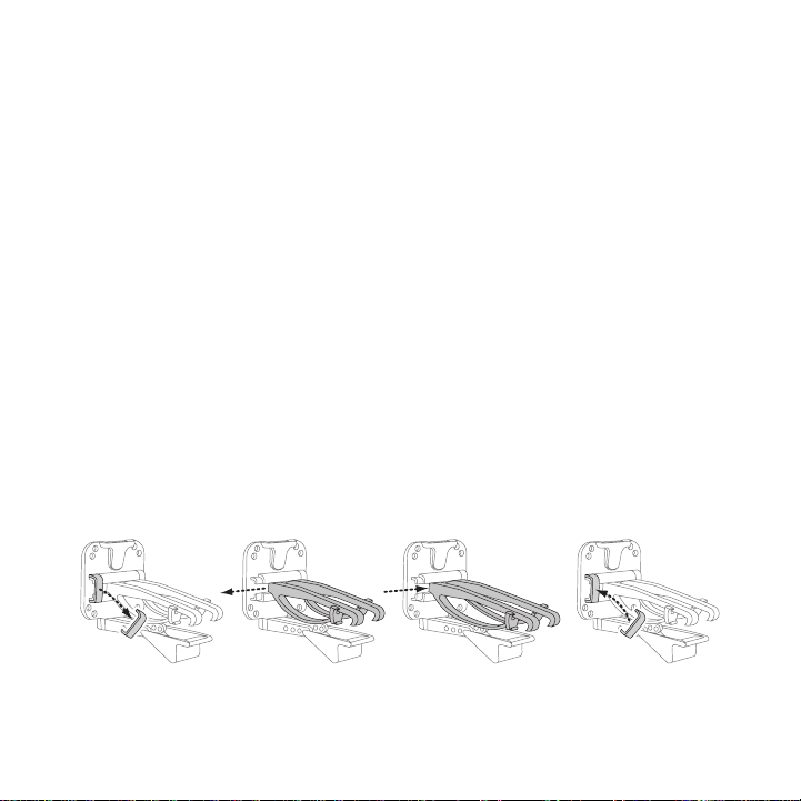
Mounting the Receiver
Slide Short
Vent Hooks Out
Remove
End Cap
Slide Extended
Vent Hooks In
Replace
End Cap
Figur e 2Figur e 2
Attach the desired mou nting device, dash or vent mount, to the vehicle docki ng station by
sliding the flat porti on of the mount into the slot on the back top edge of the vehicle docking
station. Gently slide the mounting device in unt il it snaps into place.
Dash Moun t Opt ion (A)
If you choose the dash mount option, be sure to select your mounting positio n carefully. Once
the mount has been adh ered to a surface, it will not be possib le to remove it and adhere it
again.
Clean the selected mou nting surface area in the vehicle with t he alcohol swab. Unscrew the
adhesive foot from the mount. Peel t he protective material off the adhesive on the foot and
press the foot firmly against the vehicle surface.
The adhesive mount should then be al lowed to adhere for a minimum of 2-4 hou rs before use.
Best adhesion occurs a fter 24 hours.
Vent Mount Opti on (B )
To mount the vehicle dock using the vent mount option, instal l the vent mount as follows:
If the vent louvers in your vehicle are recessed, you may need to use the longer vent
1.
hooks with the vent mo unt. Refer to Figure 2 and inst all the longer vent hooks into the
vent mount. Be sure to observe the orientation o f the vent hooks as shown.
[ Ins tal lat ion ]
11
Page 14
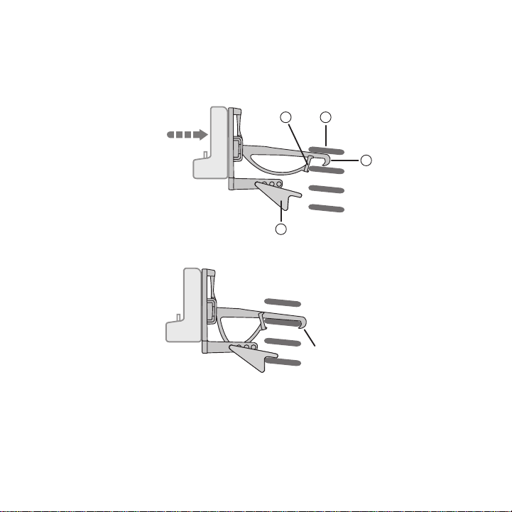
Refer to Figure 3 and attach the vent mount to a heating/air c onditioning vent in your
C
B
A
D
PUSH
HOOKED
Figur e 3Figur e 3
Figur e 4Figur e 4
2.
vehicle. Position the two tension sp rings A against a vent louver B . Then push the vent
mount into the vent, f ar enough so that the hooks C drop down and hook the rear of the
vent louver (Figure 4) . Once you are sure that the hooks have grasped a vent louver, the
tension springs A will keep the vent mount hooked to the louve r.
12
[ Ins tal lat ion ]
Page 15

The angle of the docking station may be changed by changing the position of foot D on
A
DJUSTMENT HOLES
Figur e 5Figur e 5
3.
the vent mount (Figure 3) to a different adjustment hole. (Fig ure 5)
Installing the Antenna
The optimum mounting location for th e magnetic antenna is on the roof of the vehicle, with a
minimum unobstructed a rea of 12 inch es by 12 inche s, and exactly 6½ inches from the rear
roof edge of the vehic le (the length of the rubber antenna cab le cover/tail). It is impo rtant to
avoid any obstructions that will block the SIR IUS signal, obstruct ions such as a roof rack,
a sunroof, roof mounte d cargo containers, or oth er antennas. For convertible vehicles, the
antenna should be inst alled on the trunk lid.
For best performance, it is recommen ded that the antenna be installed with the rubber
antenna cable cover/tail. This rubber antenna cable cover/tail provides two ben efits: fi rst, it
positions the antenna the recommended distance f rom the rear window, rear do or/hatch, or
trunk edge to give the antenna the best view of the sky. Secondly, it conceals and prot ects
the exposed antenna ca ble. The rubbe r antenna cable cover/tail has adhesive strips that hold
it securely in place.
The following illustrations show the recommended mounting locations of the a ntenna for
several types of vehic les. (Figure 6) Follow these recommendations for best performance from
the antenna.
[ Ins tal lat ion ]
13
Page 16

Rubber Antenna
Cover/Tail
Protective
Strips
Adhesive
Strain
Relief
Cable
Figur e 6Figur e 6
Figur e 7Figur e 7
Figur e 8Figur e 8
Seda n/Coupe. Mount the antenna along the rear center-line of the vehicle roof, located at the
rear of the roof near the rear window.
Pickup Truck. Mount the an tenna alo ng the rear center-line of the cab roof, located at the rear
of the roof near the r ear window.
SUV/Mini-Van. Mount the antenna al ong the r ear center-line of the vehicle roof, located at the
rear of the roof near the rear door/hatch.
Conv ertible. Mount the antenna along the center-line of the tr unk lid, with the rubber antenna
cable cover/t ail directed toward the rear window.
When you h ave selected a suitable mo unting location, clean the area where th e antenna and
rubber antenna cable c over/tail will be mounted with the supplied alcohol swab.
14
[ Ins tal lat ion ]
Page 17

Connect the rubber ant enna cable cover/tail to t he antenna cable, making sure that the s train-
Figur e 9Figur e 9
relief on the antenna sits into the rubber antenna cable cover /tail groove. (Figure 7) R oute the
antenna cable through the wire chann el in the rubber antenna cable cover/tail. Do not remove
the protective strips yet.
Temporarily position the antenna and rubber antenna cable cov er/t ail in the selected mo unting
area and route the cab le from the antenna to the vehicle’s int erior by tucki ng it underneath the
rubber molding around rear window, as shown in Fig ure 8.
Route the cable from t he lowest point of the rear window into the trunk. Take advantage of
any existing cable channels or wirin g conduits. Fo r SUVs, mini-vans and 5-door vehicles, bring
the cable into the veh icle under the rubber molding for the tailgate, and continue under the
interior trim.
From the trunk, or rea r of the vehicle, route the cable around the passenger compartment and
to the front of the ve hicle, to the receiver. Take care not pull the cable across sharp e dges that
could damage it, and k eep it away from areas where it might en tangle feet. Coil any exce ss
antenna cable in a loc ation where it can be hidden.
Once the antenna cable is routed through the vehicle, and you are satisfied with the cab le
routing, peel the prot ective material from the adhesive strips and press the rubber antenna
cable cover/t ail firmly into place on the vehicl e. Double check that the loc ation of the antenna
and rubber antenna cab le cover/tail are correct, and continue to press firmly down on ru b-
[ Ins tal lat ion ]
15
Page 18

90.1
Figur e 10Figur e 10
ber antenna cable cove r/tail for another 30 seconds. (Figure 9) A t room te mperature (68
degrees), maximum adhe sion usually occurs within 72 hours. During this period, avoid car
washes and other contact with the antenna and ru bber antenna cable cover/t ail.
Connect the antenna ca ble to the ANT connection at the rear of the dock. (Re fer to Figure 21
on page 23 for the loc ation of this connector.)
Connecting the Cigarette Lighter Adapter
Connect the cigarette lighter power adapter to the receiver, and plug it into your vehicle .
(Refer to Figure 21 on page 23 for the location of this connec tor.)
Maximizing Audio Quality From Your SIRIUS Receiver
There are two primary ways to connec t your SIR IUS satellite radio. The following procedures
will help you obt ain the best performance.
Wir ele ss Con neC tio n
Your SI RI US radio contains an FM transmitter. The FM tra nsmitter sends the audio from your
SIRI US radio to your vehicle radio. (Figure 10)
To tune your transmit ter:
Turn off your SIRIUS radio and tune throug h the FM channels on your vehicle radio to
1.
locate an FM channel t hat is not broadcasting in your area. If you use an F M channel
that is being used by a local broadcaster, it will interfere with the performance of your
[ Ins tal lat ion ]
16
Page 19

SIRI US radio . Once you have located an FM channel that is not broadcasting in your
area, sa ve it as a preset on your vehicle radio. This will bec ome your SIRI US prese t.
Turn on your SI RI US radio. Press and hold the Menu button to access the FM
2.
channel number list on your SI RI US radio. Tune to the channel that mat ches the SIR IUS
preset on your vehicle radio. Refer to the M enu Optio ns/ FM Freque ncy secti on of this
manual for more detailed instructions on how to do this.
Note : The FM transmitt er in your SIRIUS rad io is automatically set to FM channel 88.1. This
may not be the best channel in your area.
Tip: If you regularly travel between cities with different active F M channel s, you may need
to find channels that are not broadc asting in each city. Several SI RI US receiver models can
store multiple FM transmit channels, so you can easily switch to the best FM channel for
each city. You will also want to set the FM channels that are not broadcastin g in each city as
presets on your vehicl e radio.
If you’re not sure whi ch FM channels are not broadcasting in your home or tr avel cities, you
can also go to http:// SIRI US.com/fmchannel and search for a suggested F M channel based
on your zip code.
Dir eCt Co nne Cti ons
Direct connection prov ides better audio performance than a wir eless connection and removes
the possibility of int erference from local F M br oadcasters.
Dire ct Wi red Audio Conne ction
If your vehicle radio offers an “AUX I N” or “LIN E I N” connection, it is the best audio connection available. If the “AUX I N” or “LIN E I N” connector is located on the front of your vehicle
radio, this is also th e easiest connection. (Figure 11)
Purchase an audio cable that matches the connectio n type of your vehicle radio and
1.
your SI RI US radio at your local electronics ret ailer. Your SIRIUS rad io requires a 1/8”
stereo male connector. Your local electronics reta iler can help you determine the proper
connection for your ca r radio.
Plug one end of the ca ble into the AUDI O jack on your SI RI US radio. (Refer to Figur e
2.
21 on page 23 for the location of this connector.) Plug the other end into your “AUX IN”
or “LIN E I N” jack on your vehicle radio.
[ Ins tal lat ion ]
17
Page 20

FM OFF
FM OFF
FM OFF
Figur e 11Figur e 11
Figur e 12Figur e 12
Figur e 13Figur e 13
NOTE: Refe r to your vehicle radio manufacturer’s g uidelines for correct inst allation.
NOTE: If t he “AUX IN” or “LI NE IN” connection is on the back of your v ehicle radio, you may
want to consider profe ssional installation. (Fig ure 12)
Cass ette Adapter
If your vehicle radio has a cassette player:
Purchase a Cassette Adapter at your local electronics retailer.
1.
Connect the adapter be tween the AUDIO j ack on your SIR IUS radio (refer to Figure
2.
21 on page 23 for the location of this connector) and the vehi cle radio’s cassette slot.
(Figure 13)
NOTE: Refe r to the cassette adapter manufacturer’s guidelines for correct use.
18
[ Ins tal lat ion ]
Page 21

SI RI US FM Direct Adapter
90.1
FM
DIRECT
ADAPTER
Figur e 14Figur e 14
If your vehicle radio does not have an “AUX IN” or “LI NE IN” jack, the SIR IUS FM Direct
Adaptor provides a wir ed connection between your SI RI US radio and your vehicle radio, eliminating the outside static and interference you s ometimes experience when using a wireles s
FM conne ction. (Figure 14)
Professional inst allation may be required. See y our local SI RI US retailer.
[ Ins tal lat ion ]
19
Page 22

Subscribing to the SIRIUS Service
Channel Updates
20% Completed
To Activate Call
1-888-539-SIRIUS
1 8 4 T r a f / W x
Figur e 15Figur e 15
Figur e 16Figur e 16
Before you can listen to the SIR IUS service, you nee d to subscribe to the SIRIUS Satellite
Radio service. To sub scribe, do the following:
Be sure that the recei ver is correctly installed , and that the antenna is oriented to re ceive
1.
the SIRIUS s ignal.
Turn on the receiver. After the sta rtup sequence, it will update the S IR IU S cha nnel line-
2.
up. Wait until the channel updates have complet ed before pressing any buttons. (Figure
15)
Once the channels have been updated, the display will change to
3.
To Activate Call 1-88 8-539- SIRI US and will tune to channel 184. (Figure 16) You will
not be able to listen to other chann els until you activate your SI RI US subscription.
In order to subscribe, you will need your receiver’s unique 12 -digit SIR IUS ID number
4.
(SI D). (Fig ure 17) You can display the SID by tuni ng to channel 000 by using the channel up/down buttons on receiver. You can also tune to channel 000 by momentarily
pressing the Select button, then e ntering 000 at the prompt. (The SID number is
also available on the receiver’s packaging.) Write the SID num ber down in the space
provided near the end of this user guide.
20
[ Ins tal lat ion ]
Page 23

SID
123456789012
0 0 0 S i r i u s I D
Sub Updated
Press Any Key
1 8 4 T r a f / W x
Figur e 17Figur e 17
Figur e 18Figur e 18
Have your credit card handy and contact SI RI US on the Internet at:
5.
https://w ww.siriusc anad a.ca/act ivate/
and follow the prompts to activate your subscription. You can also call SI RI US toll-free
at: 1-88 8-539-S IR IUS (1-888-53 9-7474).
When you h ave successfully subscribed to the SIR IUS service, and the receiver ha s
6.
been updated with your subscription information, Sub Updated, Press Any Key will be
displayed. (Figure 18) To continue, press any key on the rece iver.
You are now ready to begin enjoying SI RI US Satellit e Radio’s digital entertainment, and can
tune to other channels!
[ Ins tal lat ion ]
21
Page 24

1
2
3
4
5
6
8
7
6
Hank Williams, J
All My Rowdy Fri
0 1 9 B u z z S a w
Figur e 1Figur e 1
Controls
SIRIUS Stratus SV3TK1C Reference Guide
Figure 1 and the secti on following identify and describe the b uttons of the SV3TK1C receiver.
Power Button: Turns the receiver’s power On and Off.
1.
Menu Button: Used to a ccess menu options to make setup and fea ture changes. Press-
2.
ing and holding displa ys the FM Frequency menu o ption.
Jump Button: Jumps to a pre-selected traffic/weather channel.
3.
Preset/D irect Tune B uttons (0 -9): Sets and selects preset channels. Also used to
4.
directly tune channels by entering t he channel num ber.
Cate gory Previous/ Next Buttons : Navigat es throug h the category (genre) list scr een
5.
which displays SI RI US channel categories .
Chan nel Up/Down Buttons: Navigates through chann els and display screens.
6.
Sele ct Button : Selects items highlighted on the display screen . When at the default
7.
display screen, a pres s and release will display a prompt to e nter a channel number.
Sign al Strength Di splay: Displays th e signal strength of the s atellite signal.
8.
[ Con tro ls ]
22
Page 25

SIRIUS Stratus SV3TK1C Docking Station Reference
1 2 3 4
FM OUT
ANT
AUDIO
5VDC
Figur e 2Figur e 2
Guide
Figure 2 and the secti on following identify and describe the c onnectors of the SV3TK1C
receiver.
FM OUT C onnector: FM outp ut for us e with the optional FM Direct Adapter.
1.
ANT Antenna C onnector: Connection for the provided magnetic an tenna.
2.
DC5V Power Co nnector: Power connecti on for the cigarette lighter adapter.
3.
AUDIO OU T Connector: Optional audio out put conne ction for connecting to your
4.
vehicle’s audio system if you are not using the FM transmitter.
[ Con tro ls ]
23
Page 26

Operation
Artist Name
Song Title
0 0 1 C h a n n e l
Elvis Presley
One Night
0 1 3 P o p
Elvis Presley
One Night
0 1 3 1 0 : 4 9
Figur e 1Figur e 1
Figur e 2Figur e 2
Figur e 3Figur e 3
Display Screen Information
When you h ave successfully activated your SI RI US subscription, and the receiver has received the subscriptio n information from the SI RI US signal, the default display screen will be
displayed. (Figure 1)
When the r eceiver is powered on, the previously se lected channel will automatically begin
playing.
You can select to have the channel name (Figure 1 ), category name (Figure 2), or time (Fi gure
3) displayed on the de fault display screen.
To change the display, press the Menu b utton, th en select Display Opti ons Mode
and choose the desired display optio n.
24
[ Ope rat ion ]
Page 27

Changing Channels and Categories
>001 Sirius Hits
002 StarLite
P o p
>014 Classic Vin
015 Classic Rew
R o c k
>033 Area 33
034 Boombox
E l e c / D n c
Figur e 4Figur e 4
Figur e 5Figur e 5
Figur e 6Figur e 6
Pressing the Channel Up/ Down buttons will caus e the receiver to immediately t une to
the next or previous channel.
Pressing the Category P revious/ Next buttons will cause the receiver to disp lay a category and a list of channels in the cat egory. (Figure 4) Use the Channel Up/Down buttons to
navigate through the l ist, and press the Select button to choose a selected channel.
Use the Category Previo us/Next butt ons to scroll through the categories. (F igures 5 & 6)
[ Ope rat ion ]
25
Page 28

Selecting Channels Directly
Enter Channel
# ___
0 3 1 M a r g v l l e
P3 Stored
0 7 2 P u r e J a z z
Figur e 7Figur e 7
Figur e 8Figur e 8
A channel may be directly selected b y entering the channel number using 0-9 buttons on the
receiver.
To enter a channel number, momentarily press and release the Select button. At the display
prompt (Figure 7), ent er the three digit channel number.
Channel Presets
You can store up to 10 of your favo rite channels as presets for quick recall access by pressing the 0–9 buttons.
Stor ing C hanne l Pre sets
To store a favorite channel as a pr eset, do the following:
Tune the receiver to the channel yo u wish to store as a preset.
1.
Press and hold for 1 s econd the numbered preset button (0–9) i n which you wi sh to
2.
store your favorite channel. An audi ble beep will be heard and the preset nu mber you
selected will then be displayed to confirm that the channel has been stored. (Figure 8)
Note : If the preset bu tton already has a channel stored in it, the preset wi ll be replaced by the
newly stored channel.
26
[ Ope rat ion ]
Page 29

Sele cting Presets
Preset Empty
0 3 5 C h i l l
88.1 MHz
F M F r e q u e n c y
Figur e 9Figur e 9
Figur e 10Figur e 10
Press and release one of the 0–9 buttons to select a preset channel. If no channel has bee n
saved in the selected preset, the PRE SET EM PTY message will be displa yed. (Figure 9)
FM Frequency
When the F M transmitter in your SI RI US receiver is turned on, an F M radio tuned to the same
FM frequ ency as your SIRIUS r eceiver will receive the S IR IU S audio.
To quickly access the FM frequency menu, press and hold the Menu button. The current
FM frequ ency is displayed. (Figure 10) To change the FM frequency, use the Cha nnel
Up/ Down buttons and Category Previ ous/ Next buttons to adjust the FM frequency. The
Channel Up/ Down buttons adjust in 0.2 MHz increments and the Category Previous/ Next buttons adjust i n 1 MHz incr ements. Press the Select button to set the new FM
frequency.
Note : The FM frequency is 88.1 MHz by default. This frequency may not be suitable for your
area.
[ Ope rat ion ]
27
Page 30

Jump Button
Jump to NYC
0 2 2 1 s t W a v e
NYC Pending
0 2 2 1 s t W a v e
Figur e 11Figur e 11
Figur e 12Figur e 12
Pressing the Jump button will jump to a traffic/weather channel which you have chosen for
your area. This button allows you to quickly tune the traffic/weather for your area and th en
tune back to the original channel by pressing the button again. (Figure 11)
Refer to the Jump Sett ings section in the Me nu Option s section for information on configuring the Jump button for traffic/weather in your area.
If your traffic/weathe r report is not immediately available, t he display will indicate that a
jump is pending. (Figu re 12) Once your local traffic/weather r eport is ready, the receiver will
automatically tune to the traffic/weather channel. You may have to wait a few minutes for your
desired report.
Pressing the Jump button while a jump is pending will cancel the jump. Pressing the
Jump button after the receiver has tuned to the traffic/weath er report will return to the
channel to which you had been listening immediatel y prior to pressing the Jump button.
28
[ Ope rat ion ]
Page 31

Channel Lock
Enter Channel
# ___
0 3 1 M a r g v l l e
# ____
E n t e r C o d e
Figur e 13Figur e 13
Figur e 14Figur e 14
Channels may be locked so that they can only be accessed by entering a 4-dig it code. Channels which have been locked will not appear in the channel lists , and cannot be selected using
the Channel Up/ Down buttons.
Locked cha nnels can only be selected by using the direct entry method, by momentarily pressing the Select button and entering the channel n umber at the prompt by using the 0–9
buttons. (Figure 13) You will then be prompted to enter the 4-digit channel lock code before
you can access the channel. (Figure 14)
For more information on how to set t he channel lock code, and ho w to lock or u nlock chan-
nels, refer to the Cha nnel Lock section on page 36.
[ Ope rat ion ]
29
Page 32

Menu Options
>Sirius ID
FM Transmitter
M e n u O p t i o n s
123456789012
S i r i u s I D
Figur e 1Figur e 1
Figur e 2Figur e 2
To enter the Menu Opt ions page of the receiver, p ress the Menu button. (Figure 1) To
select a menu option, use the Chan nel Up/Down buttons to display the option y ou wish
to adjust, and press t he Select button. If a selection is not made within 10 seconds, the
receiver will exit the menu options mode, and revert to the la st active display mode.
To exit menu options, or any of the other menu option screens , repeatedly press and release
thee Menu bu tton until you are returned to the defau lt display screen.
The following sections explain each of the menu op tions in the order in which they are displayed on the Menu Opt ions screen.
SIRIUS ID
The Sirius ID menu option displays your 12 digit Sirius ID (SID) number. (Figure 2) The SI D
is unique to every rec eiver and is required to activate your s ervice. It is recommended that you
write this number in t he space provided near the end of this u ser guide. No adjustments are
allowed in this mode. To exit the Sirius I D menu, press the Menu.
[ Men u O pti ons ]
30
Page 33

FM Transmitter
>FM Frequency
FM On/Off
F M T r a n s m i t t e r
88.1 MHz
F M F r e q u e n c y
>On
Off
F M O n / O f f
Figur e 3Figur e 3
Figur e 4Figur e 4
Figur e 5Figur e 5
The FM Transmitter menu option provides for turning the FM transmitter On and Off, and
changing the FM frequency which the receiver will broadcast on. (Figure 3) By default, the FM
transmitter is on and the FM freque ncy is set to 88. 1 MHz. This frequency may not be suitable
for your area.
FM Fr equen cy
To change the FM freq uency, use the Channel Up/ Down buttons and C ategory
Previous/Next buttons to adjust th e FM frequency. The Channel Up/ Down but tons adjust
in 0.2 M Hz increments and the C ategory Previous/ Next buttons adjust in 1 M Hz increments. (Figure 4) Pres s the Select button to set the new FM frequency.
FM O n/Off
To turn the receiver’ s FM transmitter On or Off , use the Channel Up/ Down buttons to
select your choice and press the Se lect button. (Figure 5)
[ Men u O pti ons ]
31
Page 34

Settings
>Brightness
Contrast
D i s p l a y O p t i o n s
- +
B r i g h t n e s s
- +
C o n t r a s t
Figur e 6Figur e 6
Figur e 7Figur e 7
Figur e 8Figur e 8
The Settings menu provides for changing the bright ness and contrast of the display screen,
and the display mode o f the display screen. (Figure 6)
Brig htnes s
The Brightness menu option adjusts t he overall intensity of the LCD display to help with
viewing in different l ighting conditions. Use the Channel Up/ Down buttons to adjus t the
brightness and press t he Select button to set your choice. (Figure 7) The bar graph will
move to indicate the change.
Cont rast
The Contrast menu opti on adjusts the relationship between the background and the text on
the LCD di splay. Use the Channel Up/ Down buttons to adjust the brightness and press
the Select button to set your choice. (Figure 8) The bar graph will move to indicate the
change.
[ Men u O pti ons ]
32
Page 35

>Channel Name
Category Name
M o d e
-
+
A u d i o L e v e l
Figur e 9Figur e 9
Figur e 10Figur e 10
Mode
The Mode menu option provides for changing the def ault display screen to display either th e
channel name, category name, or time . Refer to the Display Screen I nformatio n section on
page 24 for examples.
Use the Channel Up/Down buttons to se lect the desired mode and press the Select
button to set your choice. (Figure 9 )
Audio Level
The Audio Level menu opt ion adjusts the level of the audio outpu t of the receiver. To adjus t
the audio level, use t he Chann el Up/Down b uttons to chan ge the audio level and press
the Select button to set your choice. (Figure 10 ). The bar gra ph will move to indicate the
change.
Tones
The Tones menu option is for selecti ng whether an audio tone will be heard a s you navigate
menus and lists. To turn the tones on or off, use the Channel Up/Down buttons to select
your choice and press the Select bu tton to set your choice. (Figure 11).
[ Men u O pti ons ]
33
Page 36

>On
Off
T o n e s
>Format
Time Zone
C l o c k
>12 Hour
24 Hour
F o r m a t
Figur e 11Figur e 11
Figur e 11Figur e 11
Figur e 12Figur e 12
Clock
The Clock menu option provides for adjustment of t he clock forma t, the time zone, and daylight sa vings time function. (Figure 11)
The time data for the receiver’s clock is provided via the SI RI US signal, and will update based
on the data received from the signal.
Forma t
The Format menu option is for changing the clock display format of the receiver to 12 hour
or 24 hour format. Use the Cha nnel Up/ Down buttons to select the desired format an d
press the Select butt on to set your choice. (Figure 12)
[ Men u O pti ons ]
34
Page 37

Time Zone
>Eastern
Atlantic
T i m e Z o n e
>Yes
No
D S T O b s e r v e d
DC
>NYC
C h o o s e T r a f f i c
Figur e 13Figur e 13
Figur e 14Figur e 14
Figur e 15Figur e 15
The Time Z one menu option is for changing the time zone of the r eceiver. Use the Channel Up/Down buttons to se lect the desired time zone and press the Select button to set
your choice. (Figure 13)
Dayl ight Savin gs Ti me
The Daylight Savin gs Time menu option is for turni ng the Daylight Savings Time feature On
or Off. Use the Channel Up/Down buttons to select on or off and press the Select
button to set your choice. (Figure 1 4)
Jump Settings
The Jump menu option is used to sele ct a city for Traffic and Weather reports when the
Jump button is presse d. Use the Channel Up/Down buttons to select a city and pres s
the Select button to set your choice. (Figure 15 )
[ Men u O pti ons ]
35
Page 38

Channel Lock
# ____
N e w C o d e
# ____
C o n f i r m C o d e
# ____
E n t e r C o d e
Figur e 16Figur e 16
Figur e 17Figur e 17
Figur e 18Figur e 18
The Channel Lock menu option provides the ability to lock out with password protection any
channels you do not want others to a ccess without your permission. A locked channel will not
appear in the channel list.
When acces s to a locked channel is att empted using the direct channel entry method, the
Ente r Co de screen is displayed and the channel cannot be acces sed until the correct code is
entered.
Lock/ Unlock
The Lock/U nlock menu opt ion is used for selecting speci fic channels t o either lock or unlock.
To lock or unlock a cha nnel:
If this is the first t ime that Channel Lock is being used, you will be promp ted to create
1.
and enter a four digit numerical code. (Figure 16) This code can be any four digit number from 0000 to 999 9. Th en you will be prompted again to confirm the code you just
entered. (Figure 17) If you should exit this promp t without entering a code, you will be
prompted to set a code next time you enter the Lock/Unlock men u option.
If a code has been pre viously set, the Enter Cod e prompt will be displayed. Enter your
four digit code and pr ess the Select button to continue. (Figu re 18)
When the c orrect code has been entered, a you will enter a list of channels. Use the
2.
[ Men u O pti ons ]
36
Channel Up/ Down buttons to naviga te to the chan nel you wish to lock or unlock,
Page 39

and press the Select button. A lock ed channel wil l have the lock icon displayed to the
>108 Maxim
110 Court TV
L o c k / U n l o c k
# ____
E n t e r C o d e
Figur e 19Figur e 19
Figur e 20Figur e 20
right of the channel number and name . (Figure 19)
You can continue to select channels for locking or unlocking until you are fi nished. To exit the
Lock/ Unlock menu option press the Menu b utton.
Edit Code
The Edit Code menu opt ion is used to change a previously selected channel lock code. (The
first time the Edit Co de menu option is selected you will be p rompted to enter a four digit
code as described in t he previous section.) (Figures 16 & 17)
To edit the channel lock code:
At the prompt, enter t he current four digit channel lock code. (Figure 20) If you do not
1.
enter the correct code , a message will be displa yed alerting you that the wrong code
was entered (Figure 24 ), and you will be prompted again to ent er the code again. (If you
have forgotten your Pa rent al Control code, call SIRI US Customer Servi ce for help.)
When the c orrect code is entered, you will be prom pted to enter the new channel lock
2.
code. (Figure 21)
[ Men u O pti ons ]
37
Page 40

# ____
N e w C o d e
You will then be prompted to confir m the new chan nel lock code by entering it again.
# ____
C o n f i r m C o d e
Code Saved
C o n f i r m C o d e
Wrong Code
C o n f i r m C o d e
Figur e 21Figur e 21
Figur e 22Figur e 22
Figur e 23Figur e 23
Figur e 24Figur e 24
3.
(Figure 22)
If you confirmed the c orrect channel lock code, a confirmation screen is displayed.
4.
(Figure 23) If you ent ered the wrong code, you will be alerted and you will have to repeat
the process again. (Fi gure 24)
To exit the Edit Code menu option pres s the Menu button.
[ Men u O pti ons ]
38
Page 41

SAT - +
TER - +
S i g n a l
Figur e 25Figur e 25
Signal
The Signal menu option provides a vi sual display of the strength of the SI RI US signal from the
satellit e antenna and also from terrestrial (gro und) transmitters. (Figure 25)
To exit the Signal me nu option press the Menu butto n.
Factory Default
The Factory D efault me nu option will restore most every featur e of the receiver to the original
factory settings. The following is a list of all features affected by the Fa ctory Default option:
All Presets are cleare d
•
Receiver set to Normal Tuning Mode
•
Display brightness set to 50%
•
Display Contrast set t o 50%
•
FM Transmitter set to On
•
FM Frequ ency set to 8 8.1 MHz
•
Jump setting is cleare d
•
Top line display mode set to Channel Name
•
Audio level set to -3d b
•
Confirmation Tone set to On
•
Note that the Channel Lock feature i s not affected by the Factory Default op tion. If a code
has been set for the channel lock, the code will n ot be reset by the Factory Default featu re,
preventing circumventi on of the chan nel lock featu re. Channels which have been locked will
remain locked.
[ Men u O pti ons ]
39
Page 42

When you p erform a Factory Default, you will be pr ompted twice to confirm that you really
Yes
>No
R e s t o r e ?
Yes
>No
A r e Y o u S u r e ?
Restoring
Figur e 26Figur e 26
Figur e 27Figur e 27
Figur e 28Figur e 28
want to proceed. (Figu res 26 & 27)
If you choose to proceed, the receiv er will confirm that the factory default s are being restored.
(Figure 28) When the Factory Default is complete, the receiver will display Call 1-888-539-
SI RI US to Su bscribe, the preview channel. The receiver is still subscribed to th e SIRIUS
service.
[ Men u O pti ons ]
40
Page 43

Troubleshooting
Symp tom Solu tion
Receiver does not
power on
Receiver displays: No
Ante nna
Receiver displays:
Acquiring Signal
Audio st atic or loss of
clarity
No sound The audio cables are not connected, or the FM radio is set to the
Blown fuse, or the pow er cable is not properly connected.
Check for a bad fuse and check power cable connection
The satellite antenna is not connected to the receiver.
Check the satellite an tenna connection to the receiver.
No s atel lite signal is being received.
Check for obstacles ov er or around the satellite antenna.
Change the vehicle loc ation to eliminate nearby obstacles
(bridges, overpasses, tress, buildings, etc.).
The FM frequency contains static.
Locate a quiet FM frequency on your vehicle radi o and set the FM
transmitter frequency of the receiver to match.
If using the AUDIO OUT conne ctor, check the cable con nections.
wrong frequency. Check t he audio cables at the receiver and the
radio. Tune the FM radio to the s ame FM frequency the receiver
is tuned.
[ Troubles hoo tin g ]
41
Page 44

Specifications
Satellit e Frequencies . . . . . . . . . . . . . . . . . . . . . . . . . . . . . . . . . . . . . .2322.293/ 2330.207 MHz
Terrestrial Frequenci es . . . . . . . . . . . . . . . . . . . . . . . . . . . . . . . . . . . . . . . . . . . . . . 2326.25 0MHz
Receiver Power Requirements . . . . . . . . . . . . . . . . . . . . . . 4.9–5.6 Volts, Negative Ground, D C
Cigarette Lighter Adap ter Power Requ irements . . . . . . . . . . 9–16 Volts, Negative Ground, DC
Audio Output . . . . . . . . . . . . . . . . . . . . . . . . . . . . . . . . . . . . . . . . . . . . 550mVrms (+/- 50mVrms)
Total H armonic Distortion (TH D) . . . . . . . . . . . . . . . . . . . . . . . . . . . . . . . . . . . . . . . . . . . . <0.2%
Signal-to-noise (S/N) . . . . . . . . . . . . . . . . . . . . . . . . . . . . . . . . . . . . . . . . . . . .Greater than 73dB
Fuse Requirement . . . . . . . . . . . . . . . . . . . . . . . . . . . . . . . . . . . . . . . . . . . . . . . . . . . . . . 2A ATC
Receiver Dimensions (L ength x Width x Depth) . . . . . . . . . . . 114.3mm x 48.26mm x 1 5.24mm
Receiver Weight . . . . . . . . . . . . . . . . . . . . . . . . . . . . . . . . . . . . . . . . . . . . . . . . . . . 85.0g (3.0 oz.)
Antenna Type . . . . . . . . . . . . . . . . . . . . . . . . . . . . . . . . . . . . . . . . . . . . . . . Low Profile Magnetic
Antenna Cable Length . . . . . . . . . . . . . . . . . . . . . . . . . . . . . . . . . . . . . . .21’ (singl e micro-cable)
Connector Type . . . . . . . . . . . . . . . . . . . . . . . . . . . . . . . . . . . . . . . . . . . . . . . . SM B (right-angle)
Audio Interface . . . . . . . . . . . . . . . . . . . . . . . . . . . . . . . . . . . . . . . . . . . 1/8” / 3.5mm Ste reo Jack
FM Out I nterface . . . . . . . . . . . . . . . . . . . . . . . . . . . . . . . . . . . . . . . . . . . . . . . . . . . . 2.5mm Jack
Note: Features and Specifications ar e subject to change without notice.
[ Spe cif ica tio ns ]
42
(4.5” x 1.9” x 0.6”)
Page 45

Warranty
12 M onth Warranty
SIRIUS Canada Inc. (the “Company”) wa rrant s to the original r etail pur chaser of this produ ct that
should th is pr oduct or any part t hereo f, under normal use and conditions, be prov en de fective in
material or wo rkmanship within 12 mont hs from the date of orig inal purchase, such defect(s) will be
replaced with new or reconditione d pro duct (at the Compan y’s o ption) without charg e for parts and
labor. To obtain r eplac ement within the te rms o f this Warranty, the product is to be delivered with
proof of warra nty coverage (e.g. dated bill of sale), specificatio n of defect(s), transpor tati on pr epaid,
to the lo catio n shown below under WARR ANTY RET UR N.
This Warrant y does not extend t o the elimination of ext ernal ly generated static or noise , to correction
of antenn a pro blems, to costs inc urred for inst allation, removal o r rei nsta llation of the prod uct, or to
damage to tapes, c ompac t discs, speakers, acces sories, or vehicle elect rical systems.
This Warrant y does not apply to any product or part the reof which, in the o pinion of the Compa ny,
has suffe red o r been damaged thro ugh a lteration, improper inst alla tion, mishandling, misus e, ne glect,
accident, or b y removal or deface ment of the factory seri al nu mber/bar code label (s). THE EXTENT
OF THE COM PANY’S LIABILITY UNDER THIS WAR RANTY I S LI MIT ED TO THE RE PAIR OR
RE PLAC EM ENT PROVID ED ABOVE AN D, I N N O EVE NT, SH ALL THE COM PANY’S LIABILITY
EXCEED TH E PU RCHASE PR ICE PAID BY PU RCHASE R FO R TH E PROD UCT.
This Warrant y is in lieu of all othe r express warrantie s or liabilities. ANY I MPLIE D WAR RANT IES,
INCLU DING ANY I MPL IE D WAR RANTY OF ME RCH ANTABI LITY, S HALL BE LIMITE D TO THE
DURATION OF THI S WR ITTE N WAR RANTY. ANY ACTI ON F OR B REACH OF ANY WAR RANT Y
HE RE UN DER INCLU DING ANY IMPLIED WARRANTY O F M ERCHANTAB ILITY M UST BE
BROUG HT W ITH IN A PE RIOD OF 4 8 MONTH S FR OM DATE OF ORIGI NAL PURCHASE. IN N O
CASE SHAL L TH E COMPANY BE LIABLE FOR ANY C ONSEQUENTIAL OR INC ID ENTAL DAMAGE S FO R BREAC H OF THIS O R ANY OTHER WARRANTY, EX PRESS OR IMPLIED, WHATSOEVE R. No person or rep resen tati ve is authorized to assu me fo r the Company any l iabil ity other than
expressed here in in connection wi th th e sa le of this product. Some sta tes d o not allow limitations
on how lo ng an implied warranty l asts or the exclusion or limi tati on of incident al or conseque ntial
damage so the above limitations or exclusi ons m ay not apply to you . This Warranty g ives you specific
legal rig hts a nd you may also hav e oth er rights which vary from state to state.
WARRANTY RETURN: To obtain a replacement withi n the terms of this Warran ty, please retur n
product t o an authorized Sirius C anada ret ailer or call Erikson Co nsume r Customer Service at (8 00)
567-327 5 for an authorized Siri us re tail er near you; proof of pu rchase and desc ripti on of defect are
required. Prod ucts to be returned to a n approved warranty station must be shipped freight prepa id.
[ Warranty ]
43
Page 46

SIRIUS ID
Write down the SIRIUS ID ( SID) of your SI RIUS Stratus SV3TK1C in the space provided
below.
SID: _______________________________________
44
[ SI RI US I D ]
Page 47

SI RI US Custo mer Service: 1-88 8-539-7474
customercare@siriuscan ada.ca
SI RI US Canad a Inc.
135 Liberty Street, 4t h Floor
Toronto, Ont ario M6K 1A7
1-888-539-7474
http://www.siriuscanada.ca
Page 48

SI R I U S C anada I nc .
135 Liberty Street, 4th Floor
Toronto, Ontario M6K 1A7
1-888-539-7474
www.siriuscanada.ca
SIR IUS St ratus SV3T K1C (06-0 926A)
 Loading...