

Page 1
SIRIUS STRATUS
Satellite Radio Plug-n-Play
Installation & User Guide
Page 2

Page 3

Congratulations on the Purchase of your new SIRIUS Stratus SV3
Plug-n-Play Radio
Your new SIRIUS Stratu s SV3 Plug-n-Play Radio lets you enjoy S IRIUS® Satellite Radio’s
digital entertainment in any vehicle where yo u’ve inst alled the included vehicle docking station.
The Stratus SV3 is als o compatible with the SUPH1 SIRIUS Unive rsal Plug and Play Home
Kit, the SUPV1 SIRIUS Universal Plug and Play Vehicle Kit, and the SUBX1 SIRIUS Plug and
Play Universal Boombox (each sold separately).
Use this manual to fam iliarize yourself with all of the Stratu s’ features and capabilities. For the
latest information abo ut this and other SIRIUS products and ac cessories, visit http://www.
sirius.com.
Page 4

Table of Contents
TABLE OF CONTENTS . . . . . . . . . . . . . . . . . . . . . . . . . . . . . . 2
WARNING AND SAFETY INFORMATION . . . . . . . . . . . . . . . . . . . . . . 4
FCC Information . . . . . . . . . . . . . . . . . . . . . . . . . . . . . . . .4
Canadian Compliance . . . . . . . . . . . . . . . . . . . . . . . . . . . . . . 5
General Precautions . . . . . . . . . . . . . . . . . . . . . . . . . . . . . . . 5
Warnings . . . . . . . . . . . . . . . . . . . . . . . . . . . . . . . . . . . 6
COPYRIGHTS & TRADEMARKS . . . . . . . . . . . . . . . . . . . . . . . . . 8
PACKAGE CONTENTS . . . . . . . . . . . . . . . . . . . . . . . . . . . . . . 9
INSTALLATION . . . . . . . . . . . . . . . . . . . . . . . . . . . . . . . . 11
Location . . . . . . . . . . . . . . . . . . . . . . . . . . . . . . . . . . . 11
Mounting the Vehicle Dock . . . . . . . . . . . . . . . . . . . . . . . . . . . 12
Installing the Antenna . . . . . . . . . . . . . . . . . . . . . . . . . . . . . 15
Connecting the Cigarette Lighter Adapter . . . . . . . . . . . . . . . . . . . . . 18
Maximizing Audio Quality From Your SIRIUS Radio . . . . . . . . . . . . . . . . . . 19
Wireless Connection . . . . . . . . . . . . . . . . . . . . . . . . . . . . 19
Direct Connections . . . . . . . . . . . . . . . . . . . . . . . . . . . . . 31
Subscribing to the SIRIUS Service . . . . . . . . . . . . . . . . . . . . . . . . 34
CONTROLS . . . . . . . . . . . . . . . . . . . . . . . . . . . . . . . . . 36
SIRIUS Stratus SV3 Reference Guide . . . . . . . . . . . . . . . . . . . . . . . 36
SIRIUS Stratus SV3 Vehicle Dock Reference Guide . . . . . . . . . . . . . . . . . 37
OPERATION . . . . . . . . . . . . . . . . . . . . . . . . . . . . . . . . . 38
Display Screen Information . . . . . . . . . . . . . . . . . . . . . . . . . . . 38
Changing Channels and Categories . . . . . . . . . . . . . . . . . . . . . . . . 39
Selecting Channels Directly . . . . . . . . . . . . . . . . . . . . . . . . . . . 40
FM Frequency . . . . . . . . . . . . . . . . . . . . . . . . . . . . . . . . 41
Jump Button . . . . . . . . . . . . . . . . . . . . . . . . . . . . . . . . . 42
Channel Lock . . . . . . . . . . . . . . . . . . . . . . . . . . . . . . . . . 43
MENU OPTIONS . . . . . . . . . . . . . . . . . . . . . . . . . . . . . . . 44
SIRIUS ID . . . . . . . . . . . . . . . . . . . . . . . . . . . . . . . . . . 44
FM Transmitter . . . . . . . . . . . . . . . . . . . . . . . . . . . . . . . . 45
[ Tab le of Con ten ts ]
2
Page 5

Audio Level . . . . . . . . . . . . . . . . . . . . . . . . . . . . . . . . . 47
Tones . . . . . . . . . . . . . . . . . . . . . . . . . . . . . . . . . . . . 47
Clock . . . . . . . . . . . . . . . . . . . . . . . . . . . . . . . . . . . . 48
Jump Settings . . . . . . . . . . . . . . . . . . . . . . . . . . . . . . . . 49
Channel Lock . . . . . . . . . . . . . . . . . . . . . . . . . . . . . . . . . 50
Signal . . . . . . . . . . . . . . . . . . . . . . . . . . . . . . . . . . . . 53
Factory Default . . . . . . . . . . . . . . . . . . . . . . . . . . . . . . . . 53
OPTIONAL ACCESSORIES . . . . . . . . . . . . . . . . . . . . . . . . . . . 55
TROUBLESHOOTING . . . . . . . . . . . . . . . . . . . . . . . . . . . . . 57
SPECIFICATIONS . . . . . . . . . . . . . . . . . . . . . . . . . . . . . . . 58
WARRANTY . . . . . . . . . . . . . . . . . . . . . . . . . . . . . . . . . 59
SIRIUS ID . . . . . . . . . . . . . . . . . . . . . . . . . . . . . . . . . . 60
[ Tab le of Con ten ts ]
3
Page 6

Warning and Safety Information
FCC Information
This device complies w ith part 15 of the FCC Rules. Operation is subject to the following two
conditions:
This device may not ca use harmful interference, and
1.
This device must accep t any interference received, including i nterference that may cause
2.
undesired operation.
Note: This equipment h as been tested and found to comply with the limits for
a CLASS B digital devi ce, pursuant to Part 15 of the FCC Rules . These limits
are designed to provid e reasonable protection against harmful interference
when the equipment is operated in a commercial environment. Th is equipment
generates, uses, and c an radiate radio frequency energy and, i f not installed
and used in accordance with the instructions, may cause harmfu l interference
to radio communication s. However, there is no guarantee that i nterference will
not occur in a particu lar installation. If this equipment does cause harmful interference to radio or television reception , which can be determined by turning the
equipment off and on, the user is encouraged to try to correct the interference
by one or more of the following measures:
Reorient or relocate t he receiving antenna.
1.
Increase the separatio n between the equipment and the receiver .
2.
Connect the equipment into an outlet on a circuit different fr om that to
3.
which the receiver is connected.
Consult the dealer or an experienced radio/TV technician for h elp.
4.
WARN ING
Changes or modificatio ns not expressly approved by the manufac turer could void the user’s
authority to operate t he equipment.
[ War nin g a nd Saf ety Informatio n ]
4
Page 7

Canadian Compliance
This Class B digital a pparatus complies with Canadian ICES-003 .
Cet appareil numérique de la classe B est conforme à la norme NMB-003 du Canada.
General Precautions
Liqu id Cr ystal Precautions
If the LCD screen on t he radio is damaged, do not to touch the liquid crystal fluid. If any of the
following situations h appen, take the action indicated:
If the liquid crystal fluid comes in contact with your skin, w ipe the skin area with a cloth
1.
and then wash the skin thoroughly with soap and running water.
If the liquid crystal fluid gets into your eye, flush the eye with clean water for at least 15
2.
minutes. Seek medical care.
If the liquid crystal fluid is ingested, flush your mouth thor oughly with water. Drink large
3.
quantities of water an d induce vomiting. Seek medical care.
Safe ty Pr ecaut ions
Be sure to observe the following warnings. Failure to follow t hese safety instructions and
warnings may result in a serious accident.
Do not operate the rad io in a way that might divert your atten tion from driving safely. As a
•
driver, you alone are responsible for safely operating your ve hicle in accordance with traffic safety laws at all times.
Do not install the uni t where it may obstruct your view throug h the windshield, or of your
•
vehicle’s indicator di splays.
Do not install the uni t where it may hinder the function of sa fety devices such as an airbag.
•
Doing so may prevent t he airbag from functioning properly in t he event of an accident.
Be sure the unit is in stalled as described in the installation instructions which accompany
•
each accessory kit. SI RIUS Satellite Radio is not responsible for issues arising from installations which were not installed according to the instructions .
[ War nin g a nd Saf ety Informatio n ]
5
Page 8

To avoid short circuit s, do not open the unit, and never put o r leave any metallic objects
•
(coins, tools, etc.) i nside the unit.
If the unit emits smok e or unusual odors, turn the power off i mmediately, and disconnect
•
the unit from any powe r source.
Do not drop the unit o r subject it to strong shocks.
•
If the unit doesn’t se em to be working properly, turn the unit off, remove the battery from
•
the unit, wait 10 seco nds, replace the battery and then turn i t on again.
The installation and u se suggestions contained in this manual are subject to any restric-
•
tions or limitations t hat may be imposed by applicable law. Th e purchaser should check
applicable law for any restrictions or limitations before inst alling and/or operating this unit.
Do not install the FM Extender Antenna where it will hinder or block your view. In some
•
states it may be illeg al to mount it on the windshield of your vehicle. Check applicable
law for any restrictio ns or limitations before installing the FM Extender Antenna on your
windshield.
Do not install the FM Extender Antenna where it may hinder the function of safety devices
•
such as an airbag. Doi ng so may prevent the airbag from functi oning properly in the event
of an accident.
Warnings
Noti ce To Driv ers In Califor nia a nd Mi nnesota
State law prohibits dr ivers in California and Minnesota from u sing suction mounts on their
windshields while oper ating motor vehicles. Other dashboard or friction mounting options
should be used. SIRIUS does not take any responsibility for an y fines, penalties, or damages
that may be incurred a s a result of disregarding this notice. (See California Vehicle Code Section 26708(a); Minneso ta Statutes 2005, Section 169.71)
Oper ating Temp erature
The radio is designed to operate between -20° to +85° C (-4° t o +185° F). Avoid leaving the
radio in a vehicle or elsewhere where the temperature may fall outside this range. Extreme
temperatures or extrem e temperature fluctuations can degrade t he performance of the LCD
display screen, and po ssibly damage it.
[ War nin g a nd Saf ety Informatio n ]
6
Page 9

Clea ning and M aintenance
If the radio or access ories become dirty, turn the power off a nd wipe it clean with a soft cloth.
Do not use hard cloths , strong cleaning fluids, paint thinner, alcohol, or other volatile solvents
to clean. These may ca use damage to the radio.
Ciga rette Ligh ter Adapter
The vehicle dock canno t be powered directly from a vehicle’s 1 2 VDC power system. It must
be powered using the i ncluded Cigarette Lighter Adapter only. Connecting the vehicle dock
directly to the vehicl e’s 12 VDC power system may result in da mage to the vehicle dock or
SIRIUS radio, or both.
[ War nin g a nd Saf ety Informatio n ]
7
Page 10

Copyrights & Trademarks
© 2007 SIRIUS Satellit e Radio Inc. All Rights Reserved.
® “SIRIUS”, the SIRIUS dog logo, channel names and logos are t rademarks of SIRIUS
Satellite Radio Inc. “ NFL” and the NFL Shield logo, and the NF L Sunday Drive name and logo
are registered tradema rks of the National Football League. “NH L” and the NHL Shield are
registered trademarks of the National Hockey League. “NBA” and the NBA silhouette logo are
registered trademarks of NBA Properties Inc. All other tradema rks, service marks, sports team
names, album art, and logos are the property of their respecti ve owners. All Rights Reserved.
Portions of the softwa re on this radio are licensed under the eCos License. Distribution of
eCos requires that the eCos source code be made available to S irius Satellite Radio customers. The eCos License and eCos source code are available to th e public at http://www.sirius.
com/ecoslicense.
Sirius Satellite Radio reserves all rights to all radio softwa re not covered under the eCos
license. This includes all portions of radio software that wer e not distributed to Sirius as part
of the eCos operating system.
Hardware, subscription and activation fee required. For full T erms & Conditions, visit
http://sirius.com. Pri ces and programming are subject to chang e. Not available in HI and AK.
Equipment and subscrip tion sold separately. Installation requi red with some equipment.
[ Cop yri ght s & Tr ade marks ]
8
Page 11

Package Contents
The following items ar e included with your purchase of the SIR IUS Stratus SV3 radio:
Strat us SV3 RadioStrat us SV3 Radio
Adhes ive Das h Moun tAdhes ive Das h Moun t Vent Mount &
Vent Mount &
Exten ded Ven t Hook s
Exten ded Ven t Hook s
Vehic le DockVehic le Dock
Cigar ette Li ghter
Cigar ette Li ghter
Adapt er
Adapt er
[ Pac kag e C ont ent s ]
9
Page 12

Satellite R adio Plug -n-Play
SIRIUS STRATUS
SV3 Installation & User Guide
Magne tic
Anten na
Anten na
Anten na
Anten na
Cover /Tail
Cover /Tail
Alcoh ol
Screw sScrew sMagne tic
Alcoh ol
Swab
Swab
User GuideUser Guide
Sucti on Cups (2)Sucti on Cups (2)FM Ex tender Antenn aFM Extend er Ant enna
Unpack your SIRIUS Str atus SV3 radio carefully and make sure t hat everything shown is present. If anything is mi ssing or damaged, or if your the radio f ails to operate, notify your dealer
Self Adhesiv e
Self Adhesiv e
Cable Guides (3)
Cable Guides (3)
immediately. It is rec ommended that you retain the original ca rton and packing materials in
case you need to ship your radio in the future.
[ Pac kag e C ont ent s ]
10
Page 13
Installation
A.
B.
Figur e 1Figur e 1
Installation of your S IRIUS Stratus SV3 radio is easy:
Choose a location in y our vehicle where you will mount the rad io, either on the dash or
1.
the vent.
Mount the radio on the dash using the adhesive mount, or on a vent using the vent mount.
2.
Install the magnetic a ntenna on the roof of the vehicle, and r oute the antenna cable to
3.
the radio.
Decide whether to use a wireless connection or a direct connection to listen to your radio.
4.
Connect the power cord for the radio to your vehicle’s cigaret te lighter.
5.
Subscribe to the SIRIU S service and begin enjoying the SIRIUS entertainment!
6.
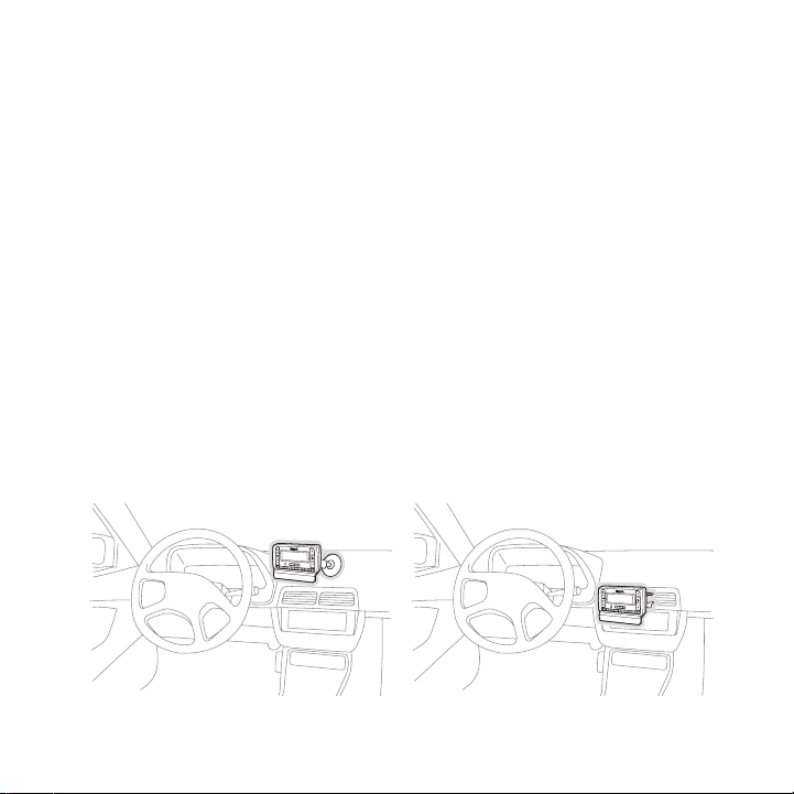
Location
Choose a location in y our vehicle where the radio will not blo ck your vision, interfere with the
vehicle controls, or o bstruct the air bag. If you are using th e adhesive mount, the location
should be a suitable f lat, smooth surface. The location should be easily reachable and provide
good visibility of the radio.
Figure 1 illustrates t he dash mount option (A), and the vent m ount option (B).
[ Ins tal lat ion ]
11
Page 14
Mounting the Vehicle Dock
Figur e 2Figur e 2
Dash Moun t Opt ion (A)
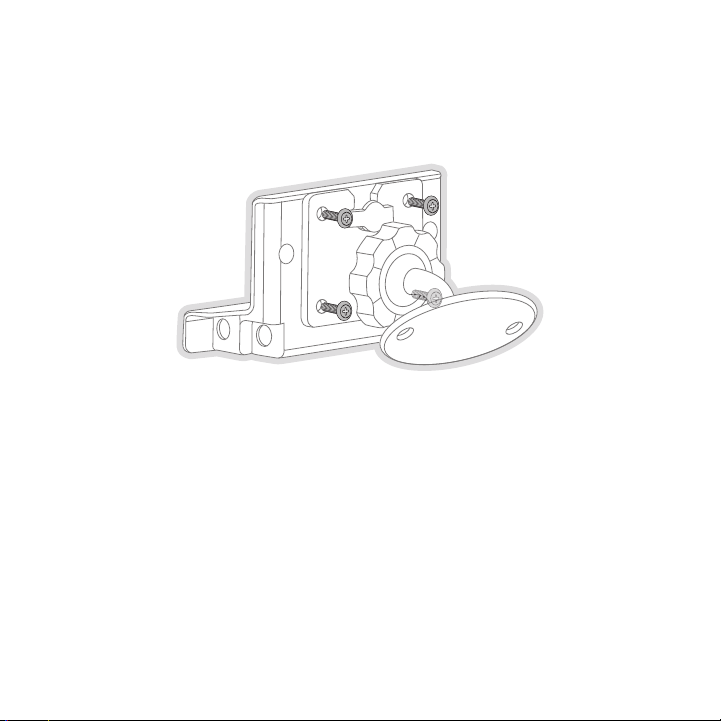
Attach the dash mount to the vehicle dock using the provided screws. (Figure 2)
Before adhering the mo unt to your vehicle, be sure to select t he mounting position carefully.
Once the mount has bee n adhered to a surface, it will not be p ossible to remove it and adhere
it again.
Clean the selected mou nting surface area in the vehicle with t he alcohol swab. Unscrew the
adhesive foot from the mount. Peel the protective material off the adhesive on the foot and
press the foot firmly against the vehicle surface.
The adhesive mount sho uld then be allowed to adhere for a mini mum of 2-4 hours before use.
Best adhesion occurs a fter 24 hours.
12
[ Ins tal lat ion ]
Page 15
Vent Moun t Opt ion (B)
Slide Short
Vent Hooks Out
Remove
End Cap
Slide Extended
Vent Hooks In
Replace
End Cap
Figur e 3Figur e 3
Figur e 4Figur e 4
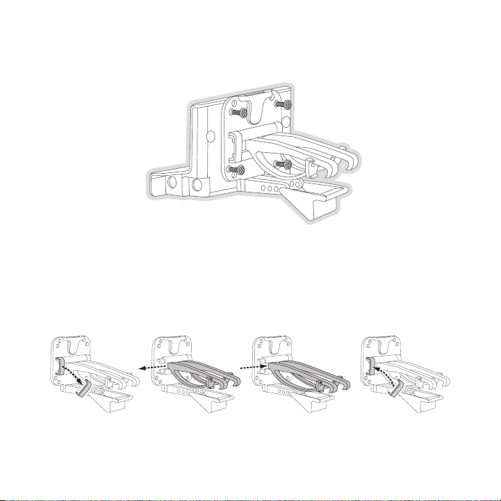
Attach the vent mount to the vehicle dock using the provided screws. (Figure 3)
To mount the vehicle d ock using the vent mount option, install the vent mount as follows:
If the vent louvers in your vehicle are recessed, you may need to use the longer vent
1.
hooks with the vent mo unt. Refer to Figure 4 and install the l onger vent hooks into the
vent mount. Be sure to observe the orientation of the vent hoo ks as shown.
[ Ins tal lat ion ]
13
Page 16

Refer to Figure 5 and attach the vent mount to a heating/air c onditioning vent in your
C
B
A
D
PUSH
HOOKED
Figur e 5Figur e 5
Figur e 6Figur e 6
2.
vehicle. Position the two tension springs A against a vent lou ver B. Then push the vent
mount into the vent, f ar enough so that the hooks C drop down and hook the rear of the
vent louver (Figure 6) . Once you are sure that the hooks have grasped a vent louver, the
tension springs A will keep the vent mount hooked to the louve r.
14
[ Ins tal lat ion ]
Page 17
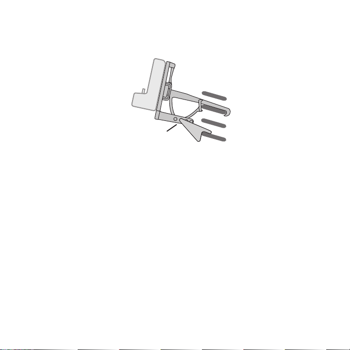
The angle of the docki ng station may be changed by changing th e position of foot D on
A
DJUSTMENT HOLES
Figur e 7Figur e 7
3.
the vent mount (Figure 5) to a different adjustment hole. (Fig ure 7)
Installing the Antenna
The optimum mounting l ocation for the magnetic antenna is on t he roof of the vehicle, with a
minimum unobstructed a rea of 12 inches by 12 inches, and exact ly 6½ inches from the rear
roof edge of the vehic le (the length of the rubber antenna cab le cover/tail). It is important to
avoid any obstructions that will block the SIRIUS signal, obst ructions such as a roof rack,
a sunroof, roof mounte d cargo containers, or other antennas. F or convertible vehicles, the
antenna should be inst alled on the trunk lid.
For best performance, it is recommended that the antenna be in stalled with the rubber
antenna cable cover/ta il. This rubber antenna cable cover/tail provides two benefits: first, it
positions the antenna the recommended distance from the rear w indow, rear door/hatch, or
trunk edge to give the antenna the best view of the sky. Secon dly, it conceals and protects
the exposed antenna ca ble. The rubber antenna cable cover/tail has adhesive strips that hold
it securely in place.
The following illustra tions show the recommended mounting loca tions of the antenna for
several types of vehic les. (Figure 8) Follow these recommendat ions for best performance from
the antenna.
[ Ins tal lat ion ]
15
Page 18
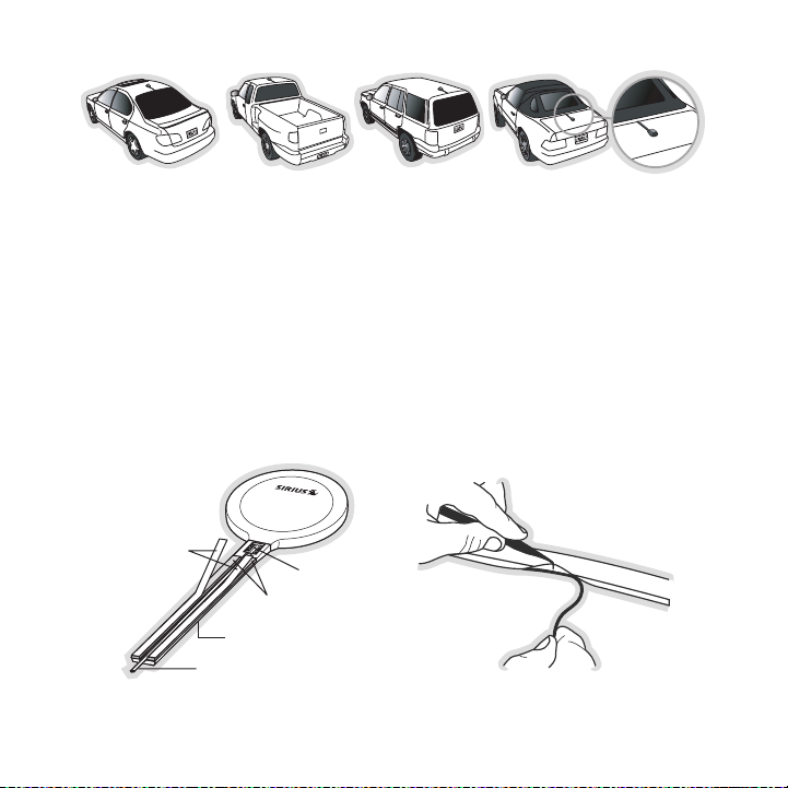
Rubber Antenna
Cover/Tail
Protective
Strips
Adhesive
Strain
Relief
Cable
Figur e 8Figur e 8
Figur e 9Figur e 9
Figur e 10Figur e 10
Seda n/Coupe. Mount the antenna along the rear center-line of the vehicle roof, located at the
rear of the roof near the rear window.
Pick up Truck. Mount th e antenna along the rear center-line of the cab roof, located at the
rear of the roof near the rear window.
SUV/ Mini-Van. Mount th e antenna along the rear center-line of the vehicle roof, located at the
rear of the roof near the rear door/hatch.
Conv ertible. Mount the antenna along the center-line of the tr unk lid, with the rubber antenna
cable cover/tail direc ted toward the rear window.
When you have selected a suitable mounting location, clean the area where the antenna and
rubber antenna cable c over/tail will be mounted with the suppl ied alcohol swab.
16
[ Ins tal lat ion ]
Page 19

Connect the rubber ant enna cable cover/tail to the antenna cab le, making sure that the strain-
Figur e 11Figur e 11
relief on the antenna sits into the rubber antenna cable cover /tail groove. (Figure 9) Route the
antenna cable through the wire channel in the rubber antenna c able cover/tail. Do not remove
the protective strips yet.
Temporarily position t he antenna and rubber antenna cable cove r/tail in the selected mounting
area and route the cab le from the antenna to the vehicle’s int erior by tucking it underneath the
rubber molding around rear window, as shown in Figure 10.
Route the cable from t he lowest point of the rear window into the trunk. Take advantage of
any existing cable cha nnels or wiring conduits. For SUVs, mini -vans and 5-door vehicles, bring
the cable into the veh icle under the rubber molding for the ta ilgate, and continue under the
interior trim.
From the trunk, or rea r of the vehicle, route the cable around the passenger compartment and
to the front of the ve hicle, to the radio. Take care not pull the cable across sharp edges that
could damage it, and k eep it away from areas where it might en tangle feet. Coil any excess
antenna cable in a loc ation where it can be hidden.
Once the antenna cable is routed through the vehicle, and you are satisfied with the cable
routing, peel the prot ective material from the adhesive strips and press the rubber antenna
cable cover/tail firml y into place on the vehicle. Double chec k that the location of the antenna
and rubber antenna cab le cover/tail are correct, and continue to press firmly down on rub-
[ Ins tal lat ion ]
17
Page 20

ber antenna cable cove r/tail for another 30 seconds. (Figure 1 1) At room temperature (68
degrees), maximum adhe sion usually occurs within 72 hours. Dur ing this period, avoid car
washes and other conta ct with the antenna and rubber antenna c able cover/tail.
Connect the antenna ca ble to the ANT connection at the rear of the dock. (Refer to Figure 2
on page 37 for the loc ation of this connector.)
Connecting the Cigarette Lighter Adapter
Connect the cigarette lighter power adapter to the radio, and plug it into your vehicle. (Refer
to Figure 2 on page 37 for the location of this connector.)
18
[ Ins tal lat ion ]
Page 21
Maximizing Audio Quality From Your SIRIUS Radio
90.1
There are two primary ways to connect your SIRIUS radio to you r vehicle radio: Wireless
Conn ection or Direct C onnection. The following sections will h elp you obtain the best perfor-
mance. For the latest information go to http ://www.si rius.com/ vehicleinstallation.
Wir ele ss Con neC tio n
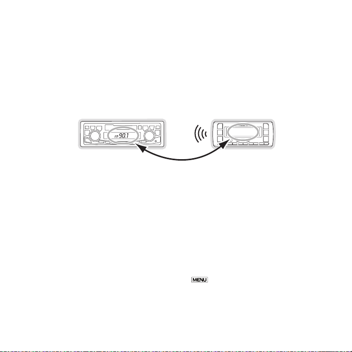
Your SIRIUS radio cont ains an FM transmitter. The FM transmitt er sends the audio from your
SIRIUS radio to your v ehicle radio. (Figure 12)
Figur e 12Figur e 12
Included with your SIR IUS radio is an FM Extender Antenna to m aximize the audio quality of
your SIRIUS radio when using a wireless audio connection. Shou ld the wireless audio quality without the FM Ext ender Antenna be not acceptable, you can try using the FM Extender
Antenna (or opt for a direct connection).
Wire less Audio Connection Wi thout the FM Extender An tenna
To tune your vehicle’s FM radio and your SIRIUS radio to the s ame FM channel (Figure 12):
Turn off your SIRIUS r adio and tune through the FM channels on your vehicle radio to
1.
locate an FM channel t hat is not broadcasting in your area. If you use an FM channel
that is being used by a local broadcaster, it will interfere w ith the performance of your
SIRIUS radio. Once you have located an FM channel that is not broadcasting in your
area, save it as a pre set on your vehicle radio. This will bec ome your SIRIUS preset.
Turn on your SIRIUS ra dio. Press and hold the Menu button to access the FM
2.
channel number list on your SIRIUS radio. Tune to the channel that matches the SIRIUS
preset on your vehicle radio. Refer to the F M Frequen cy sectio n on page 41 for more
detailed instructions on how to do this.
[ Ins tal lat ion ]
19
Page 22

Note : The FM transmitter in your SIRIUS radio is aut omaticall y set to FM channel
88.1. This may not be the best channel in your area.
Tip: If you regularly travel between cities with different ac tive FM channels , you may
need to find channels that are not broadcasting in each city. Several SIRIU S radio
models can store multiple FM transmit channels, so you can easil y switch to the
best FM channel fo r each city. Refer to your user guide for details on this featur e.
You will also want to set the FM channels that a re not broadcasting in each city as
presets on your vehicl e’s radio.
If you’re not sure whi ch FM channels are not broadcasting in y our home or travel cities, you
can also go to http:// www.sirius.com/fmchann el and search for a suggested FM channel
based on your zip code .
Wire less Audio Connection Us ing t he FM Extender Ante nna
The purpose of the FM Extender Antenna is to maximize the audi o quality of your SIRIUS radio
when using the FM tran smitter in your SIRIUS radio to transmit the audio to your vehicle’s FM
radio. Proper placemen t of the FM Extender Antenna inside your vehicle in close proximity
to the vehicle’s own F M antenna will provide a strong FM signa l for good reception. The FM
Extender Antenna has p ermanent adhesive mounts for installing it on your vehicle’s window.
Because of the differe nt kinds of FM antennas found in vehicle s, and the varied locations of
the antenna in each ve hicle, SIRIUS suggests professional inst allation of this product in your
vehicle. Professional installation provides an experienced tec hnician to install this product in
your vehicle, knowledg e of your vehicle for locating the vehic le’s FM antenna, installation of
this product, and rout ing the cable and connecting it to your SIRIUS radio. Ask your SIRIUS
retailer if they provi de professional installation services, o r can recommend a professional
installation service.
20
[ Ins tal lat ion ]
Page 23
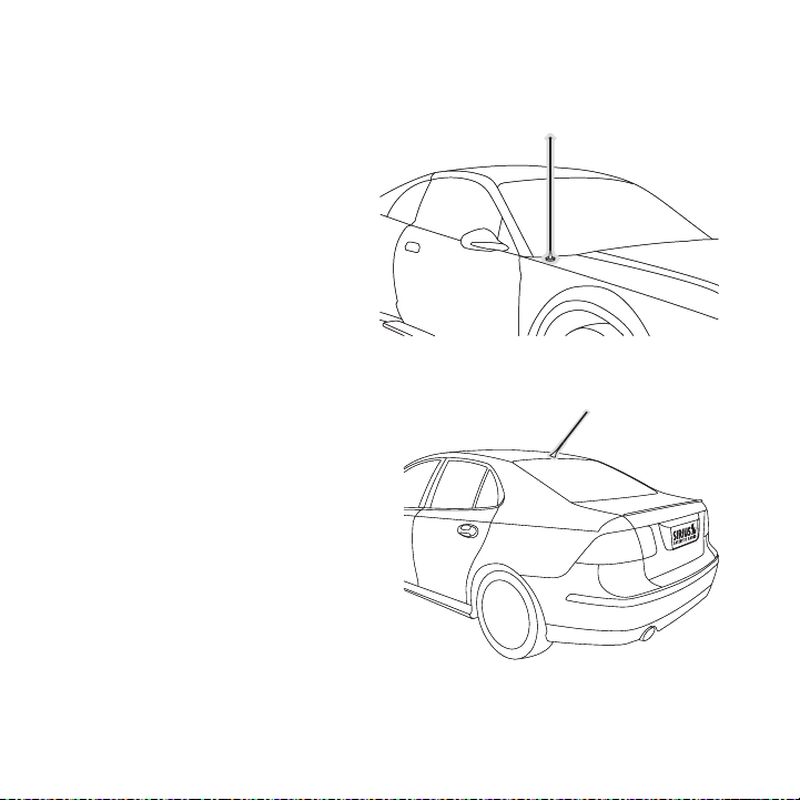
The FM antennas found in vehicles are of four distinct types:
Aeri al Type F ender Mou nted FM
•
Ante nna: A fixed or re tractable aerial
antenna located on the front or rear
fender of the vehicle.
Aeri al Type R oof Mount ed FM An-
•
tenn a: A fixed aerial antenna mounted
on the roof (often at the front or rear of
the roof, just above t he window glass).
[ Ins tal lat ion ]
21
Page 24
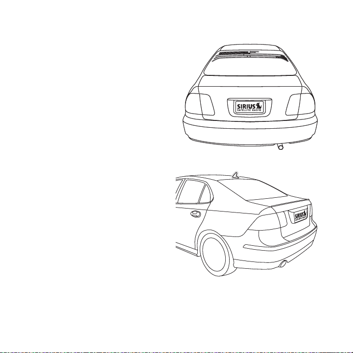
On G lass Type FM Anten na: Wires on
•
the window glass of th e vehicle, usually
near the top of the wi ndow. It may be
located on the windshi eld glass, the rear
window glass, or a rea r side window in
some SUV and mini-van type vehicles
(and other vehicles). It will look similar to
the rear window defros ter wires found in
many vehicles.
“Sha rk Fin” T ype FM An tenna: A device
•
resembling a shark fin (or other shape)
located on the vehicle roof above the rear
window.
Before attempting inst allation, you should verify the type and location of the FM antenna in
your particular vehicl e. If you have trouble locating it, cons ult the manual which accompanied
your vehicle, consult a dealer for your type of vehicle, or co nsult a professional installer.
[ Ins tal lat ion ]
22
Page 25
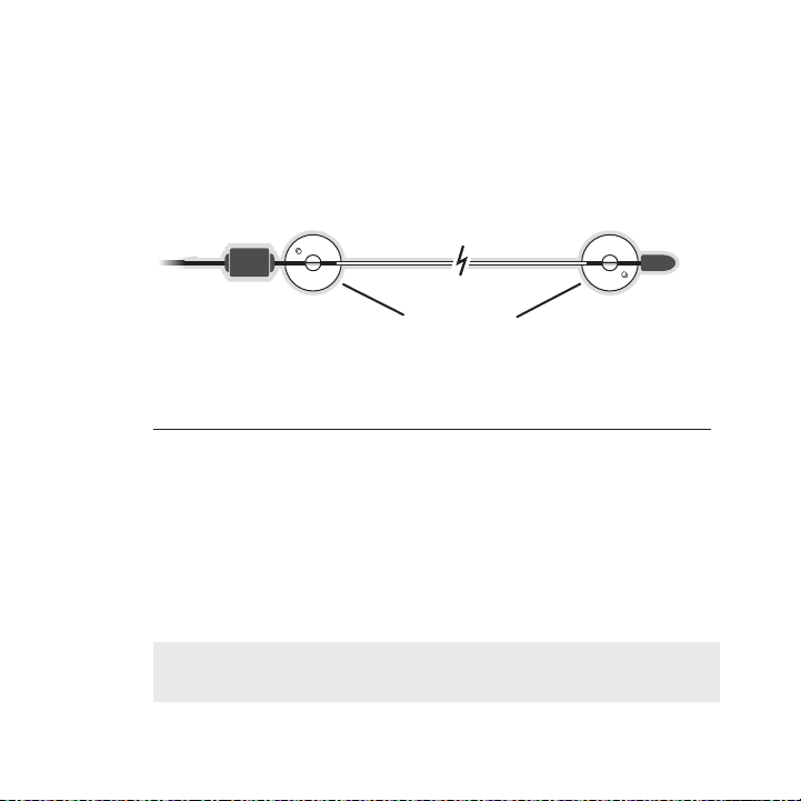
The FM Extender Antenn a should be placed inside the vehicle, a s close as possible to the
Suction Cups
vehicle’s FM antenna. A test mounting should be done first usi ng the included suction cup
mounts to test the ins tallation. Once an acceptable location h as been found, you will remove
the suction cups and p ermanently adhere the FM Extender Antenn a using the adhesive
mounts.
To install the FM Exte nder Antenna in your vehicle, follow the se instructions:
Attach the suction cup s to the FM Extender Antenna in the posi tions shown in Figure 13.
1.
Figur e 13Figur e 13
In this step, follow t he specific instructions in sub-step a, b, c, or d depending on the
2.
type of FM antenna in your vehicle:
a. Installation Instructions for Vehicles with Aerial Type Fender Mounted FM Antenna.
For vehicles where the FM radio antenna is located on the fron t fender, the FM
Extender Antenna shoul d be mounted vertically on the front win dshield at the edge
of the glass nearest t o the antenna. (Figure 14)
For vehicles where the FM radio antenna is located on the rear fender, the FM
Extender Antenna shoul d be mounted vertically on the rear wind ow at the edge of
the glass nearest to t he antenna. (Figure 15)
Attach the FM Extender Antenna to the section of glass closest to the FM antenna
in a vertical orientat ion. (Figure 14 or Figure 15) The wire b etween the two suction
cups should be pulled taut and as straight as possible, and sh ould not obstruct the
driver’s view.
Impo rtant Cau tion: In some states it may not be legal to put t he FM Extender
Impo rtant Cau tion: In some states it may not be legal to put t he FM Extender
Antenna on the windshi eld glass. In this case, the FM Extender Antenna should be
Antenna on the windshi eld glass. In this case, the FM Extender Antenna should be
mounted on the A-Pilla r adjacent to the FM antenna. (Figure 14 )
mounted on the A-Pilla r adjacent to the FM antenna. (Figure 14 )
[ Ins tal lat ion ]
23
Page 26
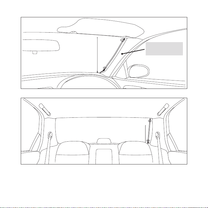
Alternate mounting
location on adjacent
A-Pillar
Figur e 14Figur e 14
24
[ Ins tal lat ion ]
Figur e 15Figur e 15
Page 27
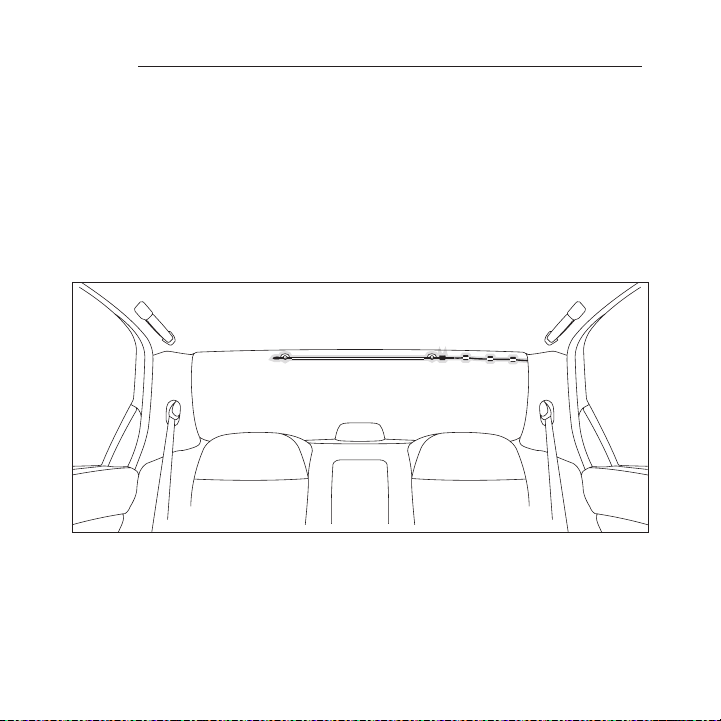
b. Installation Instructions for Vehicles with Aerial Type Roof Mounted FM Antenna.
For vehicles where the FM radio antenna is located on the fron t or rear of the
roof of the vehicle, t he FM Extender Antenna should be mounted horizontally on
the front or rear glas s below the FM antenna, or installed int o the headliner of the
vehicle under the FM a ntenna.
If you are installing the FM Extender Antenna on the window gl ass, attach the
•
suction cups to the gl ass under the FM antenna in a horizontal orientation. The
wire between the two s uction cups should be pulled taut and as straight as possible, and should not obstruct the driver’s view. (Figure 16)
If you are installing the FM Extender Antenna into the headlin er, remove the suc-
•
tion cups and tuck the wire into the headliner, stretched taut and straight, and
centered under the FM antenna.
Figur e 16Figur e 16
[ Ins tal lat ion ]
25
Page 28
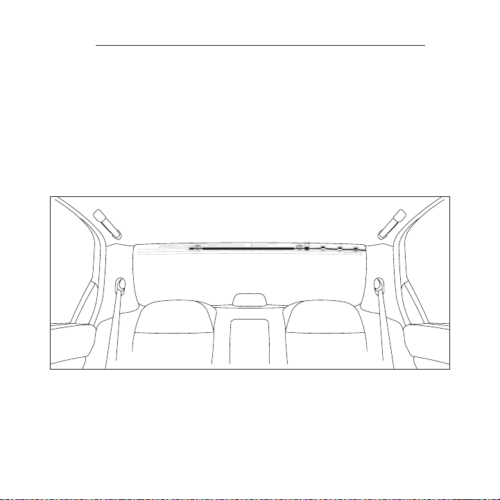
c. I nstallation Instructio ns for Ve hicles wi th On Glass Type FM An tenna.
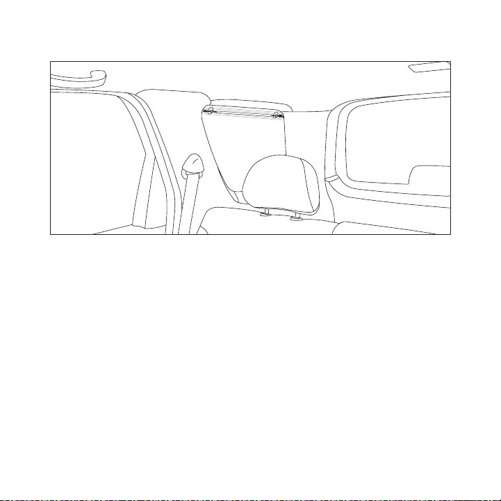
For vehicles where the FM radio antenna is located on the wind ow glass, the FM
Extender Antenna can b e mounted horizontally on the glass, dir ectly over the FM
radio antenna, or inst alled into the headliner of the vehicle directly above the FM
antenna.
If you are installing the FM Extender Antenna on the window gl ass, attach the
•
suction cups to the gl ass centered over the FM radio antenna i n a horizontal
orientation. The wire between the two suction cups should be p ulled taut and as
straight as possible, and should not obstruct the driver’s vie w. (Figures 17 & 18)
If you are installing the FM Extender Antenna into the headlin er, remove the suc-
•
tion cups and tuck the wire into the headliner, stretched taut and straight, and
centered above the FM antenna.
Figur e 17Figur e 17
26
[ Ins tal lat ion ]
Page 29
Figur e 18Figur e 18
[ Ins tal lat ion ]
27
Page 30
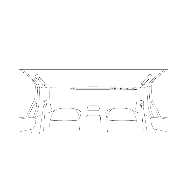
d. Installat ion Instructi ons for V ehicles w ith Shark Fin Type FM Antenna. For
vehicles where the FM radio antenna is located on the rear of the roof of the vehicle, the FM Extender Antenna should be mounted horizontally on the glass below
the FM antenna, or ins talled into the headliner of the vehicle under the FM antenna.
If you are installing the FM Extender Antenna on the window gl ass, attach the
•
suction cups to the gl ass below the FM antenna in a horizontal orientation. (Figure
19) The wire between the two suction cups should be pulled taut a nd as straight
as possible, and shoul d not obstruct the driver’s view.
If you are installing the FM Extender Antenna into the headlin er, remove the suc-
•
tion cups and tuck the wire into the headliner, stretched taut and straight, and
centered under the FM antenna.
Figur e 19Figur e 19
28
[ Ins tal lat ion ]
Page 31
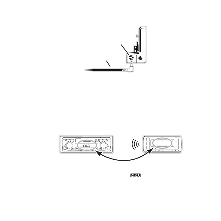
Plug the FM Extender Antenna into the FM OUT connector of the vehicle dock. (Figure 20)
FM OUT
FM OUT
ANT
From FM
Extender Cable
90.1
3.
Figur e 20Figur e 20
Tune your vehicle’s FM radio and your SIRIUS radio to the same FM channel (Figure 21):
4.
a. Turn off your SIRIUS radio and tune through the FM ch annels on your vehicle’s
radio to locate an FM channel that is not broadcasting in your area. If you use
an FM channel that is being used by a local broadcaster, it wi ll interfere with the
performance of your SI RIUS radio. Once you have located an FM channel that is
not broadcasting in yo ur area, save it as a preset on your veh icle radio. This will
become your SIRIUS pre set.
Figur e 21Figur e 21
b. Turn on your SIRIUS radio. Press and h old the Menu button to access the
FM channel number list on your SIRIUS radio. Tune to the chann el that matches the
SIRIUS preset on your vehicle radio. Refer to the FM Frequency section on page
41 for more detailed i nstructions on how to do this.
[ Ins tal lat ion ]
29
Page 32
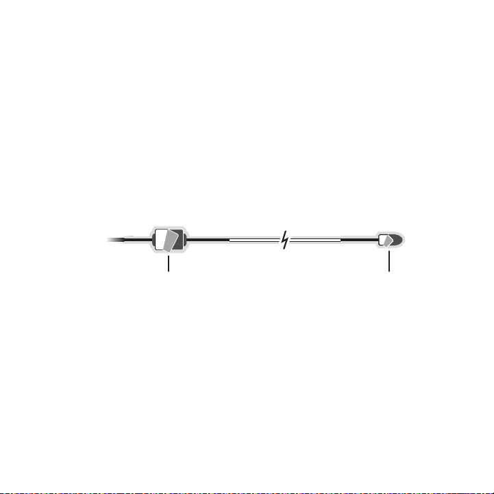
Note : The FM transmitter in your SIR IUS radio is aut omatically set to FM channel
Adhesive Adhesive
88.1. This may not be the best channel in your area.
Tip: If you regularl y travel betwee n cities with different active FM channels, you may
need to find channels that are n ot broadcast ing in each city. Several SIRIUS radio
models can store multiple FM transmit channels , so you can easily switch to the best
FM channel for each city. Refer to your user guide for de tails on thi s feat ure. You will
also want to set the FM channels that are not broadcasting in each city as presets
on your vehicle’s radi o.
You should now hear th e audio from your SIRIUS radio over your vehicle’s FM radio. If
5.
the audio quality is n ot satisfactory, try moving the FM Exten der Antenna slightly to see if
a better signal can be obtained.
If you are mounting the FM Extender Antenna in the headliner of the vehicle, skip this
6.
step. When you are satis fied with the mounting location, remove the suction cup mounts
and peel the backing o ff the adhesive mounts. Permanently adhe re it in the same position on the glass (or A-Pillar), keeping it taut and as straig ht as possible. (Figure 22)
Figur e 22Figur e 22
Route the antenna cabl e to your SIRIUS radio. Use the included self adhesive cable
7.
guides (if necessary) to hold the antenna wire in place until it reaches the weather
stripping or moulding at the edge of the window. Take advantag e of any existing cable
channels or wiring con duits and route the cable around the pas senger compartment to
the vehicle dock. Take care not pull the cable across sharp ed ges that could damage it,
and keep it away from areas where it might entangle feet. Coil and secure any excess
antenna cable in a loc ation where it can be hidden and secured .
Plug the FM Extender A ntenna into the FM OUT connector of the vehicle dock (Refer to
8.
Figure 20 on page 29.)
This completes the ins tallation of the FM Extender Antenna. If you’re not sure which FM
channels are not broad casting in your home or travel cities, y ou can also go to http://sirius .
com/ fmchannel and sear ch for a suggested FM channel based on y our zip code.
[ Ins tal lat ion ]
30
Page 33
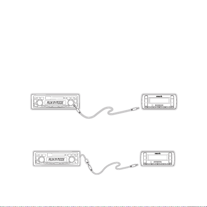
Dir eCt Co nne Cti ons
FM OFF
FM OFF
Figur e 23Figur e 23
Figur e 24Figur e 24
Direct connection prov ides better audio performance than a wir eless connection and removes
the possibility of int erference from local FM broadcasters.
Dire ct Wi red A udio Connectio n
If your vehicle radio offers an “AUX IN” or “LINE IN” connecti on, it is the best audio connection available. If the “AUX IN” or “LINE IN” connector is loca ted on the front of your vehicle
radio, this is also th e easiest connection. (Figure 23)
Purchase an audio cabl e that matches the connection type of yo ur vehicle radio and your
1.
SIRIUS radio at your l ocal electronics retailer. Your SIRIUS r adio requires a 1/8” stereo
male connector. Your l ocal electronics retailer can help you d etermine the proper connection for your car r adio.
Plug one end of the ca ble into the “AUDIO OUT” or “LINE OUT” j ack on your SIRIUS
2.
radio. Plug the other end into your “AUX IN” or “LINE IN” jack on your vehicle radio.
Note : Refer to your ve hicle radio manufacturer’s guidelines fo r correct installation.
Note : If the “AUX IN” or “LINE IN” connection is on the back o f your vehicle radio, you may
want to consider profe ssional installation. (Figure 24)
[ Ins tal lat ion ]
31
Page 34
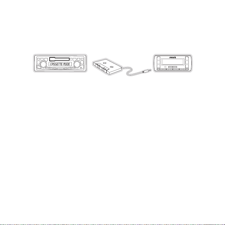
Cass ette Adapt er
FM OFF
Figur e 25Figur e 25
If your vehicle radio has a cassette player:
Purchase a Cassette Ad apter at your local electronics retailer .
1.
Connect the adapter be tween the “AUDIO OUT” or “LINE OUT” on y our SIRIUS radio
2.
and the vehicle radio’ s cassette slot. (Figure 25)
Note : Refer to the cas sette adapter manufacturer’s guidelines for correct use.
32
[ Ins tal lat ion ]
Page 35
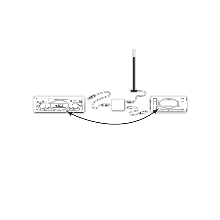
SIRI US FM Dire ct Adapter
90.1
FM
DIRECT
ADAPTER
Figur e 26Figur e 26
If your vehicle radio does not have an “AUX IN” or “LINE IN” j ack, the SIRIUS FM Direct
Adapter provides a wir ed connection between your SIRIUS radio and your vehicle radio, eliminating the outside sta tic and interference you sometimes exper ience when using a wireless
FM connection. (Figure 26)
Professional installat ion may be required. See your local SIRI US retailer.
For the latest informa tion refer to http://w ww.sirius .com/vehi cleinstallation. (The SIRIUS
FM Direct Adapter is a vailable at your local SIRIUS retailer o r at http://shop.sirius.com).
[ Ins tal lat ion ]
33
Page 36
Subscribing to the SIRIUS Service
Channel Updates
20% Completed
To Activate Call
1-888-539-SIRIUS
1 8 4 T r a f / W x
Figur e 27Figur e 27
Figur e 28Figur e 28
Before you can listen to the SIRIUS service, you need to subsc ribe to the SIRIUS Satellite
Radio service. To subs cribe, do the following:
Be sure that the radio is correctly installed, and that the an tenna is oriented to receive
1.
the SIRIUS signal.
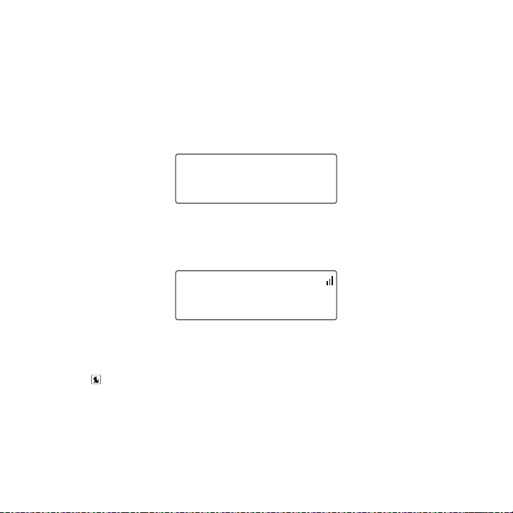
Turn on the radio. Aft er the startup sequence, it will update the SIRIUS channel line-up.
2.
Wait until the channel updates have completed before pressing any buttons. (Figure 27)
Once the channels have been updated, the display will change t o
3.
To A ctivate C all 1-888 -539-SIRIUS and will tune to channel 184 . (Figure 28) You will
not be able to listen to other channels until you activate you r SIRIUS subscription.
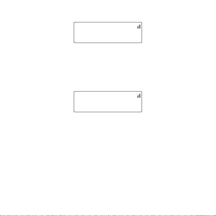
In order to subscribe, you will need your radio’s unique 12-digit SIRIUS ID number (SID).
4.
(Figure 29) You can di splay the SID by tuning to channel 000 b y using the channel
up/down buttons on rad io. You can also tune to channel 000 by momentarily pressing
the Select button, then e ntering 000 at the prompt. (The SID numb er is also available
on the radio’s packagi ng.) Write the SID number down in the sp ace provided near the
end of this user guide .
34
[ Ins tal lat ion ]
Page 37
SID
123456789012
0 0 0 S i r i u s I D
Sub Updated
Press Any Key
1 8 4 T r a f / W x
Figur e 29Figur e 29
Figur e 30Figur e 30
Have your credit card handy and contact SIRIUS on the Internet at:
5.
https://a ctivate.siriusradio.co m/
and follow the prompts to activate your subscription. You can also call SIRIUS toll-free
at: 1-888-539 -SIRIUS ( 1-888-539-7474).
When you have successf ully subscribed to the SIRIUS service, a nd the radio has been
6.
updated with your subs cription information, Sub Updat ed, Press Any Key will be displayed. (Figure 30) To continue, press any key on the radio.
You are now ready to b egin enjoying SIRIUS Satellite Radio’s d igital entertainment, and can
tune to other channels !
[ Ins tal lat ion ]
35
Page 38
1
2
3
4
5
6
8
7
6
Hank Williams, J
All My Rowdy Fri
0 1 9 B u z z S a w
Figur e 1Figur e 1
Controls
SIRIUS Stratus SV3 Reference Guide
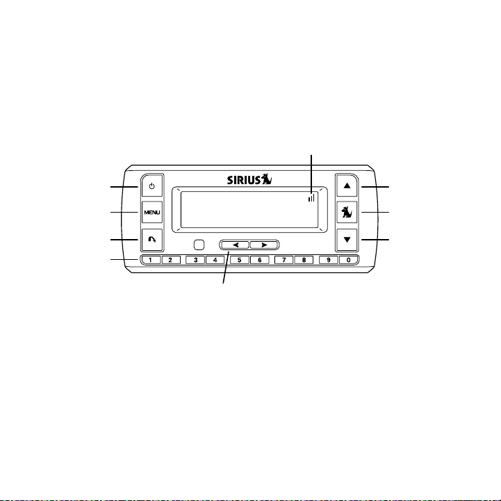
Figure 1 and the secti on following identify and describe the b uttons of the SV3 radio.
Powe r Button: Turns th e radio’s power On and Off.
1.
Menu Button: Used to a ccess menu options to make setup and fea ture changes. Press-
2.
ing and holding displa ys the FM Frequency menu option.
Jump Button: Jumps to a pre-selected traffic/weather channel.
3.
Pres et/Direct Tune But tons (0-9): Sets and selects preset chan nels. Also used to
4.
directly tune channels by entering the channel number.
Cate gory Prev ious/Next Buttons: Navigates through the category (genre) list screen
5.
which displays SIRIUS channel categories.
Chan nel Up/Do wn Button s: Navigates through channels and displa y screens.
6.
Sele ct Button : Selects items highlighted on the display screen . When at the default
7.
display screen, a pres s and release will display a prompt to e nter a channel number.
Sign al Streng th Displa y: Displays the signal strength of the s atellite signal.
8.
[ Con tro ls ]
36
Page 39
SIRIUS Stratus SV3 Vehicle Dock Reference Guide
1 2 3 4
FM OUT
ANT
AUDIO
5VDC
Figur e 2Figur e 2
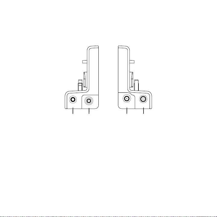
Figure 2 and the secti on following identify and describe the c onnectors of the SV3 vehicle
dock.
FM O UT Connec tor: FM o utput for use with the optional FM Direc t Adapter.
1.
ANT Antenna C onnector: Connection for the provided magnetic an tenna.
2.
DC5V Power Co nnector: Power connection for the cigarette light er adapter.
3.
AUDI O OUT Con nector: O ptional audio output connection for conn ecting to your
4.
vehicle’s audio system if you are not using the FM transmitter .
[ Con tro ls ]
37
Page 40
Operation
Artist Name
Song Title
0 0 1 C h a n n e l
Elvis Presley
One Night
0 1 3 P o p
Elvis Presley
One Night
0 1 3 1 0 : 4 9
Figur e 1Figur e 1
Figur e 2Figur e 2
Figur e 3Figur e 3
Display Screen Information
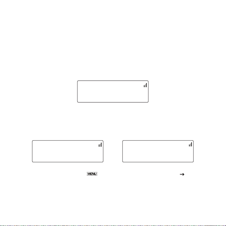
When you have successf ully activated your SIRIUS subscription, and the radio has received
the subscription infor mation from the SIRIUS signal, the defau lt display screen will be displayed. (Figure 1)
When the radio is powe red on, the previously selected channel will automatically begin playing.
You can select to have the channel name (Figure 1), category n ame (Figure 2), or time (Figure
3) displayed on the de fault display screen.
To change the display, press the Menu button, then select Display O ptions Mo de
and choose the desired display option.
38
[ Ope rat ion ]
Page 41
Changing Channels and Categories
>001 Sirius Hits
002 StarLite
P o p
>014 Classic Vin
015 Classic Rew
R o c k
>033 Area 33
034 Boombox
E l e c / D n c
Figur e 4Figur e 4
Figur e 5Figur e 5
Figur e 6Figur e 6
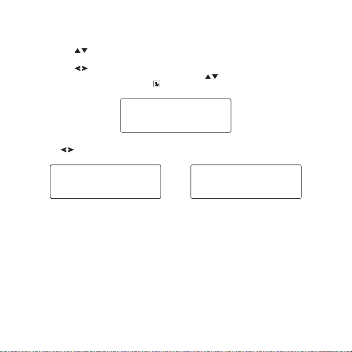
Pressing the Channel Up/Down butto ns will cause the radio to immediately t une to the
next or previous chann el.
Pressing the Category P revious/N ext buttons will cause the radi o to disp lay a category
and a list of channels in the category. (Figure 4) Use the Channel Up/Down buttons to
navigate through the l ist, and press the Select button to choose a selected channel.
Use the Category Previo us/Next buttons to scroll through the ca tegories. (Figures 5 & 6)
[ Ope rat ion ]
39
Page 42
Selecting Channels Directly
Enter Channel
# ___
0 3 1 M a r g v l l e
P3 Stored
0 7 2 P u r e J a z z
Figur e 7Figur e 7
Figur e 8Figur e 8
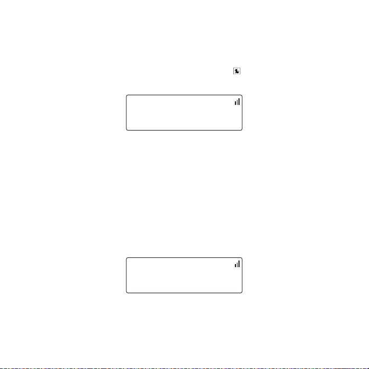
A channel may be direc tly selected by entering the channel num ber using 0-9 buttons on the
radio.
To enter a channel num ber, momentarily press and release the Sele ct button. At the display
prompt (Figure 7), ent er the three digit channel number.
Channel Presets
You can store up to 10 of your favorite channels as presets fo r quick recall access by pressing the 0–9 buttons.
Stor ing C hanne l Presets
To store a favorite ch annel as a preset, do the following:
Tune the radio to the channel you wish to store as a preset.
1.
Press and hold for 1 s econd the numbered preset button (0–9) i n which you wish to
2.
store your favorite ch annel. An audible beep will be heard and the preset number you
selected will then be displayed to confirm that the channel ha s been stored. (Figure 8)
Note : If the preset bu tton already has a channel stored in it, the preset will be replaced by the
newly stored channel.
40
[ Ope rat ion ]
Page 43
Sele cting Pres ets
Preset Empty
0 3 5 C h i l l
88.1 MHz
F M F r e q u e n c y
Figur e 9Figur e 9
Figur e 10Figur e 10
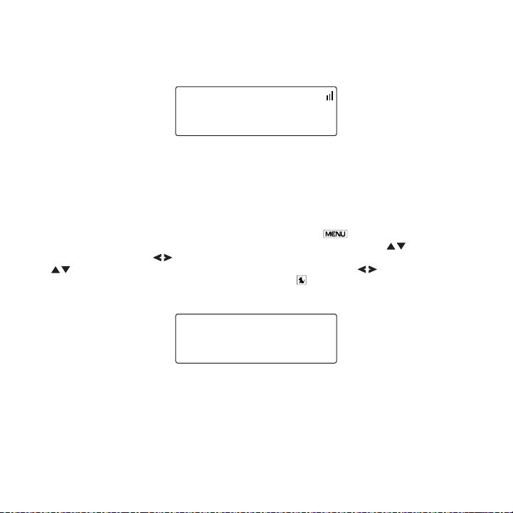
Press and release one of the 0–9 buttons to select a preset ch annel. If no channel has been
saved in the selected preset, the PRESET EMP TY message will be displayed. (Figure 9)
FM Frequency
When the FM transmitte r in your SIRIUS radio is turned on, an FM radio tuned to the same FM
frequency as your SIRI US radio will receive the SIRIUS audio.
To quickly access the FM frequency menu, press and hold the Menu bu tton. The current
FM frequency is displa yed. (Figure 10) To change the FM freque ncy, use the Channel
Up/Down buttons and Ca tegory Pr evious/Next buttons to adjust t he FM fre quency. The
Channel Up/Down butto ns adjust in 0.2 MHz increments and the C ategory P revious/Next buttons adjus t in 1 MHz increments. Press the Select but ton to set the new FM
frequency.
Note : The FM frequency is 88.1 MHz by default. This frequency may not be suitable for your
area.
[ Ope rat ion ]
41
Page 44
Jump Button
Jump to NYC
0 2 2 1 s t W a v e
NYC Pending
0 2 2 1 s t W a v e
Figur e 11Figur e 11
Figur e 12Figur e 12
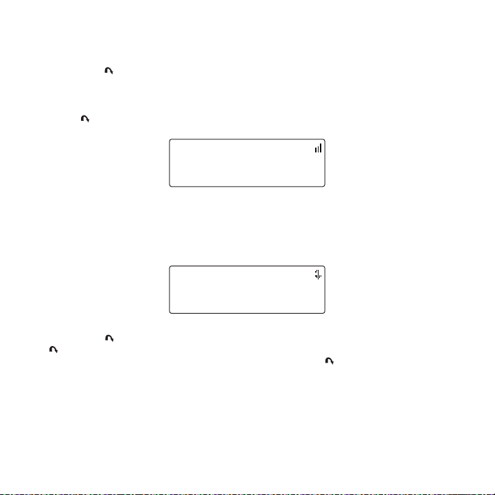
Pressing the Jump b utton wil l jump to a traffic/weather cha nnel whic h you have chosen for
your area. This button allows you to quickly tune the traffic/ weather for your area and then
tune back to the origi nal channel by pressing the button again . (Figure 11)
Refer to the Jump Sett ings section in the Me nu Option s section for information on configuring the Jump button for traff ic/weather in your area.
If your traffic/weathe r report is not immediately available, t he display will indicate that a jump
is pending. (Figure 12 ) Once your local traffic/weather report is ready, the radio will automatically tune to the traf fic/weather channel. You may have to wai t a few minutes for your desired
report.
Pressing the Jump button whil e a jump is pending will cancel the jump . Pressing the
Jump button after the radio has tuned to the traffic/weather report will return to the channel
to which you had been listening immediately prior to pressing the Jum p button.
42
[ Ope rat ion ]
Page 45
Channel Lock
Enter Channel
# ___
0 3 1 M a r g v l l e
# ____
E n t e r C o d e
Figur e 13Figur e 13
Figur e 14Figur e 14
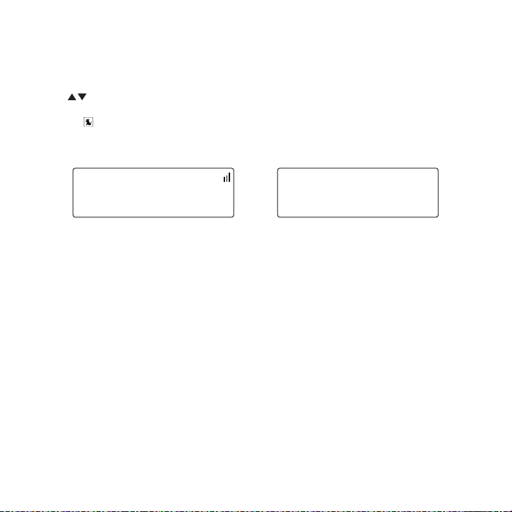
Channels may be locked so that they can only be accessed by en tering a 4-digit code. Channels which have been locked wil l not app ear in th e channel lists, and cannot be selected using
the Channel Up/Down buttons.
Locked channels can only be selected by using the direct entry method, by momentarily pressing the Select button and entering the channel number at the promp t by usin g the 0–9
buttons. (Figure 13) Y ou will then be prompted to enter the 4- digit channel lock code before
you can access the cha nnel. (Figure 14)
For more information o n how to set the channel lock code, and how to lock or unlock chan-
nels, refer to the Cha nnel Lock section on page 50.
[ Ope rat ion ]
43
Page 46
Menu Options
>Sirius ID
FM Transmitter
M e n u O p t i o n s
123456789012
S i r i u s I D
Figur e 1Figur e 1
Figur e 2Figur e 2
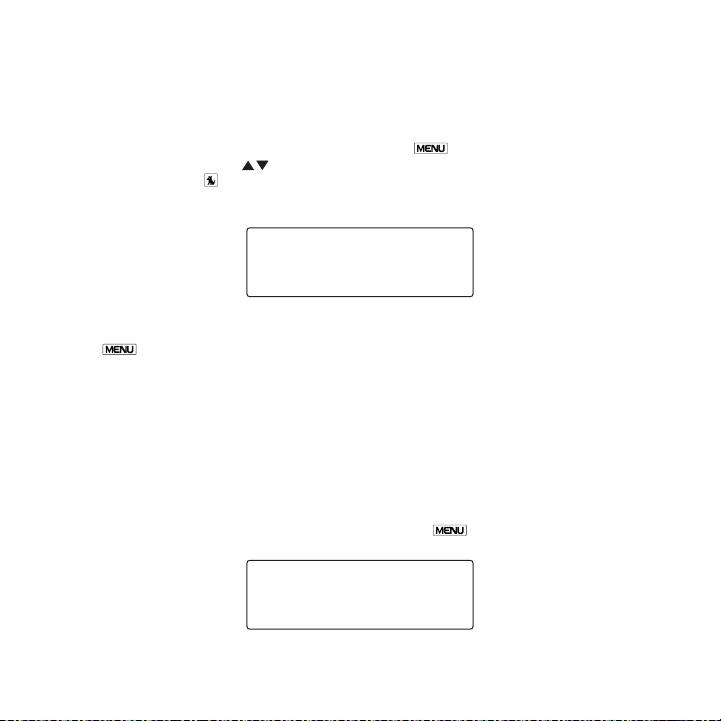
To enter the Menu Opti ons page of the radio, press the Menu button. (Figure 1) To select a menu option, us e the Channe l Up/Down buttons to display the option you wish to
adjust, and press the Sel ect button. If a selection is not made w ithin 10 seconds, the radio
will exit the menu opt ions mode, and revert to the last active display mode.
To exit menu options, or any of the other menu option screens, repeatedly press and release
thee Menu button until you are returned to the default display scre en.
The following sections explain each of the menu options in the order in which they are displayed on the Menu Opt ions screen.
SIRIUS ID
The Sirius ID menu opt ion displays your 12 digit Sirius ID (SI D) number. (Figure 2) The SID
is unique to every rad io and is required to activate your serv ice. It is recommended that you
write this number in t he space provided near the end of this u ser guide. No adjustments are
allowed in this mode. To exit the Sirius ID menu, press the Menu.
[ Men u O pti ons ]
44
Page 47
FM Transmitter
>FM Frequency
FM On/Off
F M T r a n s m i t t e r
88.1 MHz
F M F r e q u e n c y
>On
Off
F M O n / O f f
Figur e 3Figur e 3
Figur e 4Figur e 4
Figur e 5Figur e 5
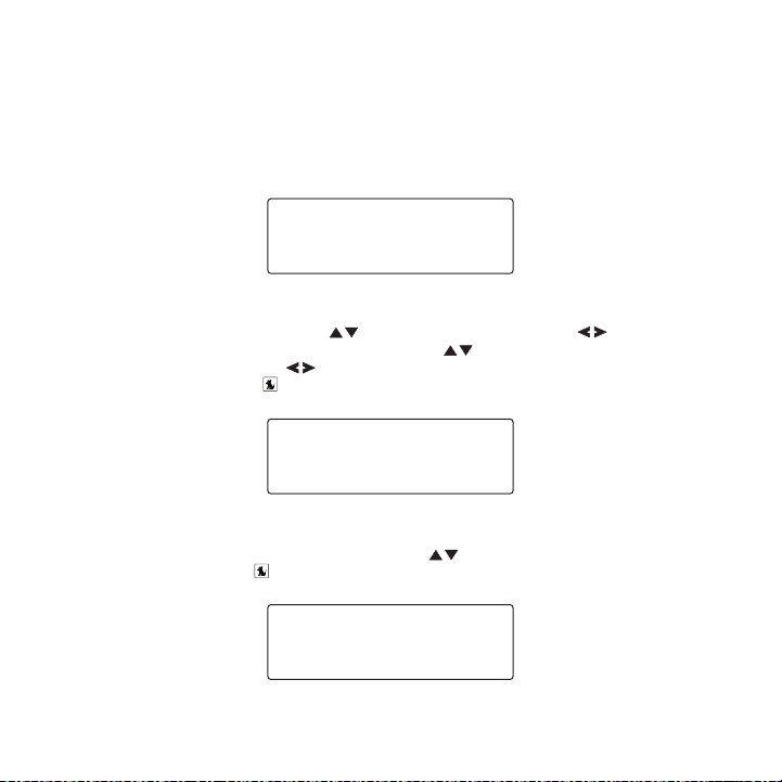
The FM Transmitter menu option provides for turning the FM transmitter On and Off, and changing the FM frequency which the radio will broadcast on. (Figure 3) By default, the FM transmitter
is on and the FM frequ ency is set to 88.1 MHz. This frequency may not be suitable for your
area.
FM F reque ncy
To change the FM frequ ency, use the Channel Up/Down butto ns and Ca tegory
Previous/Next buttons to adjust the FM frequency. The Cha nnel Up/Down buttons adjust
in 0.2 MHz increments and the Ca tegory Previous/Next buttons ad just in 1 MHz increments. (Figure 4) Pres s the Select button to set the new FM freque ncy.
FM O n/Off
To turn the radio’s FM transmitter On or Off, use the Cha nnel Up/Down buttons to select
your choice and press the Select bu tton. (Figure 5)
[ Men u O pti ons ]
45
Page 48
Settings
>Brightness
Contrast
D i s p l a y O p t i o n s
- +
B r i g h t n e s s
- +
C o n t r a s t
Figur e 6Figur e 6
Figur e 7Figur e 7
Figur e 8Figur e 8
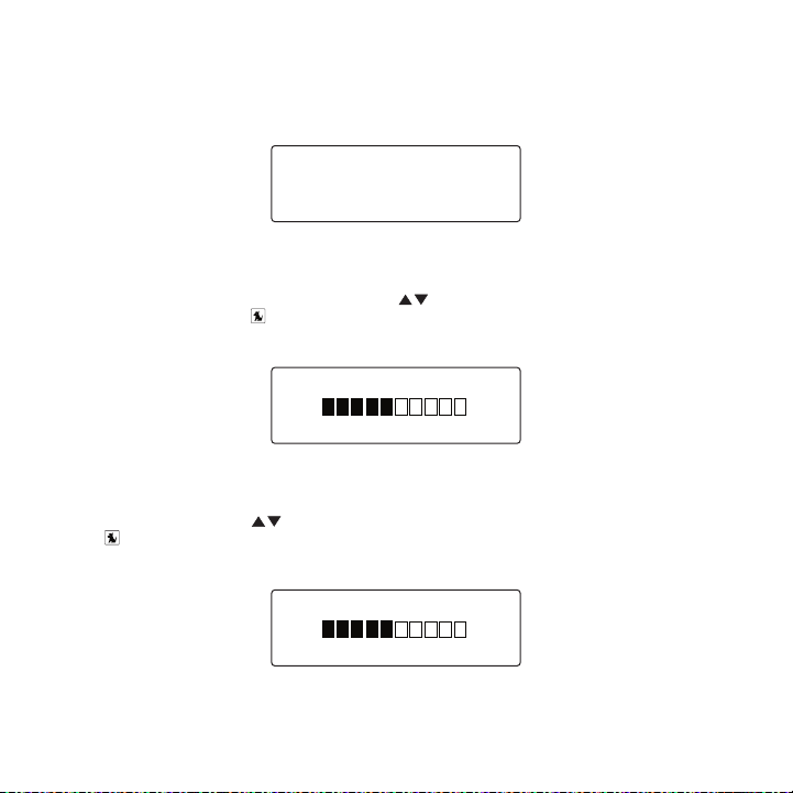
The Settings menu prov ides for changing the brightness and con trast of the display screen,
and the display mode o f the display screen. (Figure 6)
Brig htnes s
The Brightnes s menu op tion adjusts the overall intensity of th e LCD display to help with
viewing in different l ighting conditions. Use the Channel Up/Down buttons to adjust the
brightness and press t he S elect but ton to set your choice. (Figure 7) The b ar graph will
move to indicate the c hange.
Cont rast
The Contrast menu opti on adjusts the relationship between the background and the text on
the LCD display. Use t he Channel Up/Down buttons to adjus t the brightness and press
the Select button to set your choice. (Figure 8) The bar graph wi ll move to indicate the
change.
[ Men u O pti ons ]
46
Page 49
>Channel Name
Category Name
M o d e
-
+
A u d i o L e v e l
Figur e 9Figur e 9
Figur e 10Figur e 10
Mode
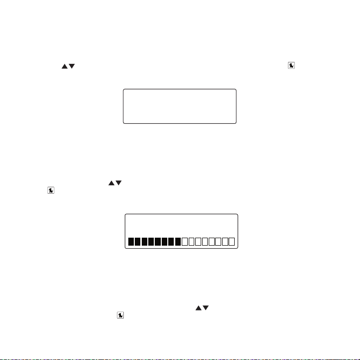
The Mode menu option p rovides for changing the default display screen to display either the
channel name, category name, or time. Refer to the Di splay Scr een Informati on section on
page 38 for examples.
Use the Channel U p/Down buttons to select the desired mod e and press the Select
button to set your cho ice. (Figure 9)
Audio Level
The Audio Lev el menu o ption adjusts the level of the audio out put of the radio. To adjust
the audio level, use t he Channel Up/Down buttons to chang e the audio level and press
the Select button to set your choice. (Figure 10). The bar graph will move to indicate the
change.
Tones
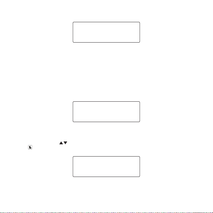
The Tones menu option is for selecting whether an audio tone w ill be heard as you navigate
menus and lists. To tu rn the tones on or off, use the Cha nnel Up/Down buttons to select
your choice and press the Select bu tton to set your choice. (Figur e 11).
[ Men u O pti ons ]
47
Page 50
>On
Off
T o n e s
>Format
Time Zone
C l o c k
>12 Hour
24 Hour
F o r m a t
Figur e 11Figur e 11
Figur e 12Figur e 12
Figur e 13Figur e 13
Clock
The Clock menu option provides for adjustment of the clock for mat, the time zone, and daylight savings time fun ction. (Figure 12)
The time data for the radio’s clock is provided via the SIRIUS signal, and will update based on
the data received from the signal.
Form at
The Format menu option is for changing the clock display forma t of the radio to 12 hour or 24
hour format. Use the Channel Up/Down buttons to select th e desired format and press
the Select button to set your choice. (Figure 13)
[ Men u O pti ons ]
48
Page 51
Time Zone
>Eastern
Atlantic
T i m e Z o n e
>Yes
No
D S T O b s e r v e d
DC
>NYC
C h o o s e T r a f f i c
Figur e 14Figur e 14
Figur e 15Figur e 15
Figur e 16Figur e 16
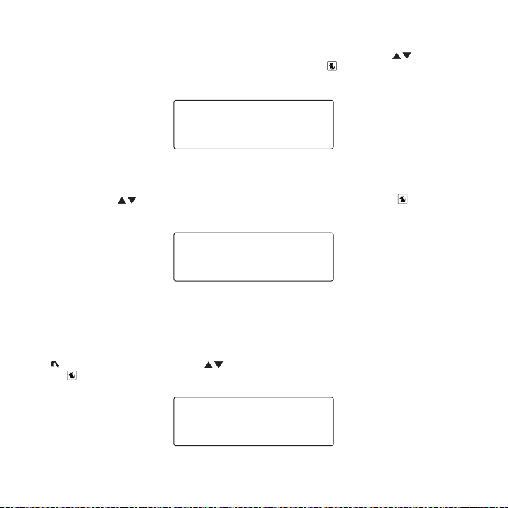
The Time Zone menu opt ion is for changing the time zone of the radio. Use the Channel
Up/Down buttons to sel ect the desired time zone and press the Sel ect button to set your
choice. (Figure 14)
Dayl ight Savin gs Time
The Daylight Savings T ime menu option is for turning the Dayli ght Savings Time feature On
or Off. Use the C hannel Up/Down buttons to select on or o ff and press the Select
button to set your cho ice. (Figure 15)
Jump Settings
The Jump menu option i s used to select a city for Traffic and Weather reports when the
Jump button is presse d. Use the Channel Up/Down buttons to select a city and press
the Select button to set your choice. (Figure 16)
[ Men u O pti ons ]
49
Page 52
Channel Lock
# ____
N e w C o d e
# ____
C o n f i r m C o d e
# ____
E n t e r C o d e
Figur e 17Figur e 17
Figur e 18Figur e 18
Figur e 19Figur e 19
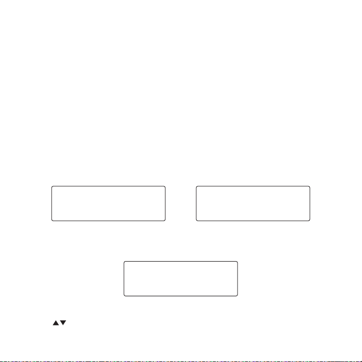
The Channel L ock menu option provides the ability to lock out with password protection any
channels you do not wa nt others to access without your permiss ion. A locked channel will not
appear in the channel list.
When access to a locke d channel is attempted using the direct channel entry method, the
Ente r Code screen is d isplayed and the channel cannot be acces sed until the correct code is
entered.
Lock /Unlo ck
The Lock/Unlo ck menu o ption is used for selecting specific cha nnels to either lock or unlock.
To lock or unlock a ch annel:
If this is the first t ime that Channel Lock is being used, you will be prompted to create
1.
and enter a four digit numerical code. (Figure 17) This code c an be any four digit number from 0000 to 9999. Then you will be prompted again to conf irm the code you just
entered. (Figure 18) I f you should exit this prompt without en tering a code, you will be
prompted to set a code next time you enter the Lock/Unlock men u option.
If a code has been pre viously set, the Enter Code prompt will be displayed. Enter your
four digit code and pr ess the Select button to continue. (Figu re 19)
When the correct code has been entered, a you will enter a lis t of channels. Use the
2.
[ Men u O pti ons ]
50
Channel Up/Down butto ns to navigate to the channel you wish t o lock or unlock,
Page 53
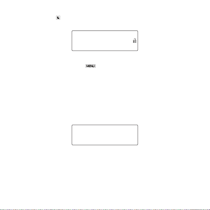
and press the Select butto n. A lock ed channel will have the lock i con displ ayed to the
>108 Maxim
110 Court TV
L o c k / U n l o c k
# ____
E n t e r C o d e
Figur e 20Figur e 20
Figur e 21Figur e 21
right of the channel n umber and name. (Figure 20)
You can continue to se lect channels for locking or unlocking u ntil you are finished. To exit the
Lock /Unlock menu optio n press the Menu button.
Edit Code
The Edit Code menu opt ion is used to change a previously selec ted channel lock code. (The
first time the Edit Co de menu option is selected you will be p rompted to enter a four digit
code as described in t he previous section.) (Figures 17 & 18)
To edit the channel lo ck code:
At the prompt, enter t he current four digit channel lock code. (Figure 21) If you do not
1.
enter the correct code , a message will be displayed alerting y ou that the wrong code
was entered (Figure 25 ), and you will be prompted again to ent er the code again. (If you
have forgotten your Pa rental Control code, call SIRIUS Custome r Service for help.)
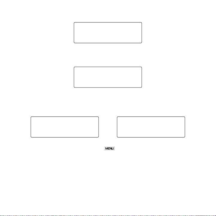
When the correct code is entered, you will be prompted to ente r the new channel lock
2.
code. (Figure 22)
[ Men u O pti ons ]
51
Page 54
# ____
N e w C o d e
You will then be promp ted to confirm the new channel lock code by entering it again.
# ____
C o n f i r m C o d e
Code Saved
C o n f i r m C o d e
Wrong Code
C o n f i r m C o d e
Figur e 22Figur e 22
Figur e 23Figur e 23
Figur e 24Figur e 24
Figur e 25Figur e 25
3.
(Figure 23)
If you confirmed the c orrect channel lock code, a confirmation screen is displayed.
4.
(Figure 24) If you ent ered the wrong code, you will be alerted and you will have to repeat
the process again. (Fi gure 25)
To exit the E dit Code menu option press the Menu button.
[ Men u O pti ons ]
52
Page 55
SAT - +
TER - +
S i g n a l
Figur e 26Figur e 26
Signal
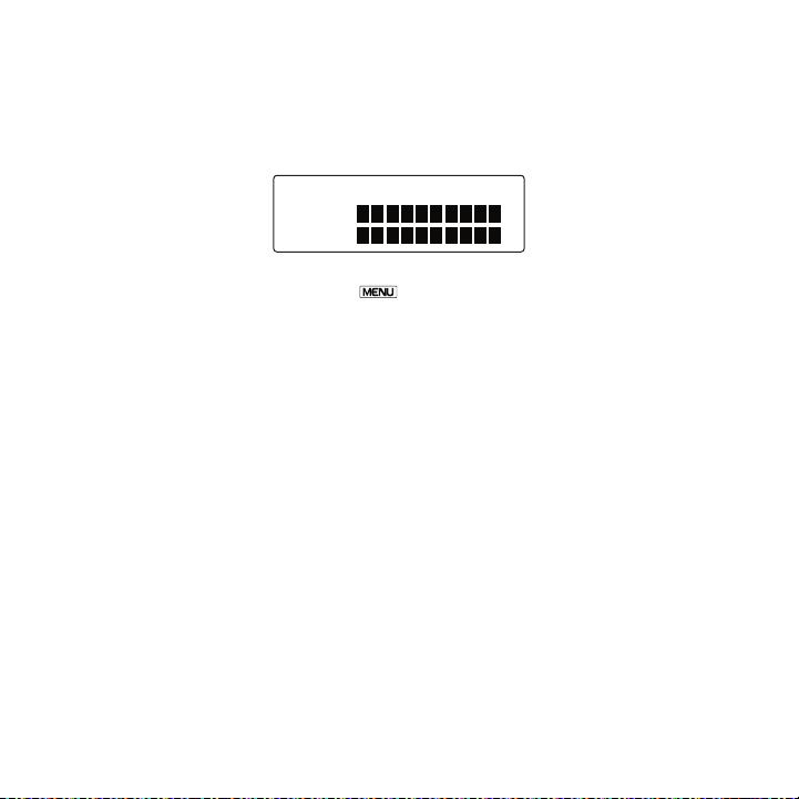
The Signal menu option provides a visual display of the streng th of the SIRIUS signal from the
satellite antenna and also from terrestrial (ground) transmitt ers. (Figure 26)
To exit the S ignal men u option press the Menu button.
Factory Default
The Factory D efault me nu option will restore most every featur e of the radio to the original
factory settings. The following is a list of all features affe cted by the Factory Default option:
All Presets are cleare d
•
Radio set to Normal Tu ning Mode
•
Display brightness set to 50%
•
Display Contrast set t o 50%
•
FM Transmitter set to On
•
FM Frequency set to 88 .1 MHz
•
Jump setting is cleare d
•
Top line display mode set to Channel Name
•
Audio level set to -3d b
•
Confirmation Tone set to On
•
Note that the Channel Lock feature is not affected by the Fact ory Default option. If a code
has been set for the c hannel lock, the code will not be reset by the Factory Default feature,
preventing circumventi on of the channel lock feature. Channels which have been locked will
remain locked.
[ Men u O pti ons ]
53
Page 56

When you perform a Fac tory Default, you will be prompted twice to confirm that you really
Yes
>No
R e s t o r e ?
Yes
>No
A r e Y o u S u r e ?
Restoring
Figur e 27Figur e 27
Figur e 28Figur e 28
Figur e 29Figur e 29
want to proceed. (Figu res 27 & 28)
If you choose to proce ed, the radio will confirm that the fact ory defaults are being restored.
(Figure 29) When the F actory Default is complete, the radio wi ll display Call 1-888- 539-SIRI-
US t o Subscri be, the p review channel. The radio is still subsc ribed to the SIRIUS service.
[ Men u O pti ons ]
54
Page 57

Optional Accessories
The following optional accessories are available for purchase from your SIRIUS retailer to
maximize your SIRIUS e xperience:
SUBX 1 SIR IUS P lug and Play U niver sal B oombox
The SUBX1 SIRIUS Plug and Play Universal Boombox is a portable docking station and audio
system for use with th e SIRIUS Sportster radio. With the built -in amplifier and speakers, the
boombox delivers rich powerful sound indoors or outdoors, and features an auxiliary input for
other audio devices,
Included with the boom box is an adjustable indoor/outdoor wind owsill antenna with 20’ of
cable and an AC adapte r.
SUPH 1 SIR IUS U niversal Plug and P lay H ome Kit
The SUPH1 SIRIUS Unive rsal Plug and Play Home Kit is a compact docking cradle that positions the radio for ea sy viewing and operation. Designed for q uick and easy self-installation, it
includes all necessary cabling to connect your SIRIUS radio to your home audio system.
The kit includes a com pact tabletop/desktop docking cradle wit h FM output for wireless
connectivity, an audio cable for connection to any stereo book shelf system, an adjustable
indoor/outdoor windows ill antenna with 20’ of cable, and an AC Adapter.
SUPV 1 SIR IUS U niversal Plug and P lay V ehicle Kit
The SUPV1 SIRIUS Unive rsal Plug and Play Vehicle Kit is a comp act docking cradle that positions the radio for ea sy wiring, viewing, and operation in an additional vehicle. Designed for
quick and easy self-in stallation, it provides several mounting options and includes all necessary cabling to connec t your SIRIUS radio to your vehicle audi o system.
The SUPV1 SIRIUS Unive rsal Plug and Play Vehicle Kit will work with the Sportster 4 and
most new SIRIUS plug a nd play radios.
The kit includes a mob ile docking cradle, a suction cup vehicl e mount, a vent mount, a cigarette lighter adapter, and a magnetic antenna with 21’ of cabl e.
[ Opt ion al Acc ess ori es ]
55
Page 58

FM D irect Adap ter
The FM Direct Adapter accessory redirects your vehicle’s FM an tenna signal when listening to
your SIRIUS radio usin g your vehicle’s AM/FM radio. When the S IRIUS radio is powered on
the FM Direct Adapter automatically redirects the vehicle’s FM antenna signal away from the
vehicle’s AM/FM radio, reducing any interference which might b e present from FM radio station broadcasts. When the SIRIUS radio is turned off, the FM a ntenna signal is automatically
redirected back to the vehicle’s AM/FM radio. (Product number 14100.)
[ Opt ion al Acc ess ori es ]
56
Page 59

Troubleshooting
Symp tom Solu tion
Radio does not power onBlown fuse, or the pow er cable is not properly connected.
Radio displays: No
Ante nna
Radio displays: Acquir ing Signa l
Audio static or loss o f
clarity
No sound The audio cables are n ot connected, or the FM radio is set to the
Check for a bad fuse a nd check power cable connection
The satellite antenna is not connected to the radio.
Check the satellite an tenna connection to the radio.
No satellite signal is being received.
Check for obstacles ov er or around the satellite antenna.
Change the vehicle loc ation to eliminate nearby obstacles
(bridges, overpasses, tress, buildings, etc.).
The FM frequency conta ins static.
Locate a quiet FM freq uency on your vehicle radio and set the FM
transmitter frequency of the SIRIUS radio to match.
If using the AUDIO OUT connector, check the cable connections.
wrong frequency. Check the audio cables at the SIRIUS radio an d
the FM radio. Tune the FM radio to the same FM frequency the
SIRIUS radio is tuned.
[ Tro ubl esh oot ing ]
57
Page 60

Specifications
Satellite Frequencies . . . . . . . . . . . . . . . . . . . . . . . . . . . . . . . . . . . . . . 2322.293/2330.207 MHz
Terrestrial Frequencie s . . . . . . . . . . . . . . . . . . . . . . . . . . . . . . . . . . . . . . . . . . . . . 2326.250MHz
Radio Power Requiremen ts . . . . . . . . . . . . . . . . . . . . . . . . 4.9–5.6 Volts, Negative Ground, DC
Cigarette Lighter Adap ter Power Requirements . . . . . . . . . . 9–16 Volts, Negative Gro und, DC
Audio Output . . . . . . . . . . . . . . . . . . . . . . . . . . . . . . . . . . . . . . . . . . . .550mVrms (+/- 50mVrms)
Total Harmonic Distort ion (THD) . . . . . . . . . . . . . . . . . . . . . . . . . . . . . . . . . . . . . . . . . . . . <0 .2%
Signal-to-noise (S/N) . . . . . . . . . . . . . . . . . . . . . . . . . . . . . . . . . . . . . . . . . . . Greater than 73dB
Fuse Requirement . . . . . . . . . . . . . . . . . . . . . . . . . . . . . . . . . . . . . . . . . . . . . . . . . . . . . . 2A ATC
Radio Dimensions (Leng th x Width x Depth). . . . . . . . . . . . . . 114.3mm x 48.26mm x 15.24mm
Radio Weight . . . . . . . . . . . . . . . . . . . . . . . . . . . . . . . . . . . . . . . . . . . . . . . . . . . . . 85.0g (3.0 oz. )
Antenna Type . . . . . . . . . . . . . . . . . . . . . . . . . . . . . . . . . . . . . . . . . . . . . . . Low Profile Magnetic
Antenna Cable Length . . . . . . . . . . . . . . . . . . . . . . . . . . . . . . . . . . . . . . . 21’ (single micro-cab le)
Connector Type . . . . . . . . . . . . . . . . . . . . . . . . . . . . . . . . . . . . . . . . . . . . . . . . SMB (right-angle)
Audio Interface . . . . . . . . . . . . . . . . . . . . . . . . . . . . . . . . . . . . . . . . . . . 1/8 ” / 3.5mm Stereo Jack
FM Out Interface . . . . . . . . . . . . . . . . . . . . . . . . . . . . . . . . . . . . . . . . . . . . . . . . . . . . 2.5mm Jack
Note: Features and Spe cifications are subject to change withou t notice.
[ Spe cif ica tio ns ]
58
(4.5” x 1.9” x 0.6”)
Page 61

Warranty
12 M onth Warra nty
SIRIUS Sa telli te Radio Inc. (the “Comp any”) warrants to t he or iginal retail purch aser of this product
that shou ld th is product or any p art t hereof, under norma l use and conditions, be prov en defective in
material or wo rkmanship within 12 mont hs from the date of orig inal purchase, such defe ct(s) will be
repaired or re placed with new or recon ditioned product (a t the Company’s option) witho ut charge for
parts and repa ir labor. To obtain repa ir or replacement w ithin the terms of this Warra nty, the product
is to be deliv ered with proof of warra nty coverage (e.g. dated bill of sale), spe cific ation of defect(s),
transport ation prepaid, to the lo catio n shown below under WARR ANTY RETURN.
This Warr anty does not extend to the e limination of exter nally generated static o r noi se, to correction
of antenn a pro blems, to costs inc urred for installation, remov al or reinstallatio n of the product, or to
damage to tape s, compact discs, s peake rs, accessories, or vehi cle electrical syst ems.
This Warr anty does not apply to a ny pr oduct or part there of wh ich, in the opinion of t he Company,
has suffe red o r been damaged thro ugh a lteration, improper inst allation, mishandli ng, m isuse, neglect,
accident, or b y removal or deface ment of the factory seri al nu mber/bar code label (s). THE EXTENT
OF THE CO MPANY ’S LIABILITY UNDER THIS WARRANTY IS LIMITED TO T HE REPAIR OR
REPLACEME NT PR OVIDED ABOVE AND, I N NO EVENT, SHALL THE CO MPANY ’S LIABILITY
EXCEED TH E PUR CHASE PRICE PAID BY PURC HASER FOR THE PRODU CT.
This Warr anty is in lieu of all o ther express warranties or li abilities. ANY IMPL IED W ARRANTIES, INCLUDING A NY IM PLIED WARRANTY OF M ERCHA NTABILITY, SHALL BE LIMI TED TO THE DURATION OF T HIS W RITTEN WARRANTY. AN Y ACT ION FOR BREACH OF A NY WA RRANTY HEREUNDER INC LUDIN G ANY IMPLIED WARRA NTY O F MERCHANTABILITY M UST B E BROUGHT
WITHIN A PERIO D OF 48 MONTHS FROM DATE OF ORIGINAL PURCHA SE. I N NO CASE SHALL
THE COMPA NY BE LIABLE FOR ANY CON SEQUE NTIAL OR INCIDENTAL DAMA GES FOR
BREACH OF THIS OR ANY OTHER WARRA NTY, EXPRESS OR IMPLIED, WHAT SOEVER. No
person or repr esentative is autho rized to assume for the Compa ny any liability ot her t han expressed
herein in conn ection with the sal e of this product. Some state s do not allow limi tatio ns on how long
an implie d war ranty lasts or the exclu sion or limitation of in cidental or consequ entia l damage so the
above lim itati ons or exclusions m ay no t apply to you. Thi s War ranty gives you spe cific legal rights and
you may a lso h ave other rights wh ich v ary from state to s tate.
WARRANTY RETUR N: To obtain repair or r eplacement within t he te rms of this Warrant y, pl ease return prod uct t o an authorized ret ailer or call Customer S ervic e at 1-800-869-5590 ; pro of of purchase
and descr iptio n of defect are req uired . Products to be re turne d to an approved wa rrant y station must
be shippe d fre ight prepaid.
[ War ran ty ]
59
Page 62
SIRIUS ID
Write down the SIRIUS ID (SID) of your SIRIUS Stratus SV3 in t he space provided below.
SID: _______________________________________
60
[ SIR IUS ID ]
Page 63
SIRI US Custom er Servic e: 1-888-539-7474
customercare@sirius-ra dio.com
SIRI US Satell ite Radio Inc.
1221 Avenue of the Ame ricas
New York, NY 10020
1-888-539-7474
http://www.sirius.com
Page 64
SI RI US Sate ll ite Rad io Inc.
1221 Avenue of the Americas
New York, NY 10020
(800) 869-5590
http://sirius.com
SIRIUS Stratus SV3 (0118 07a)
 Loading...