

Page 1

Congratulations on your purchase!
Thank you for choosing a Sirius product.
SL906 series & SL907 700
UNDERMOUNT RANGEHOOD INSTALLATION INSTRUCTIONS
SL906 L 520 EAN #9351116000677
SL906 L 850 EAN #9351116000745
SL906L EXCEL 850 EAN #9351116000806
SL906L EXCEL1000 EAN #9351116000899
SL906L EXCEL 1200 EAN #9351116002015
SL907 700 EAN #9351116000714
www.siriusbrand.com
1
Page 2
CAUTION
BEFORE YOU INSTALL – please read
Sirius warranty covers only Sirius product. If you choose to install a non-Sirius
branded accessory such as flexible ducting, Sirius will only warrant the hood
and motor. If installation is found to be the cause of failure or issue then charges
will apply for service and parts.
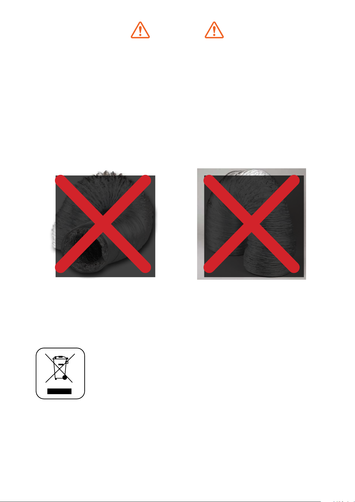
Flexible ducting is not permitted under any circumstances. Flexible ducting has
been found to increase noise levels, increase vibration and reduce airflow.
Sirius Semi-rigid or solid ducting can be used in lieu. There is a range available
to suit any application.
Ducting available at www.siriusbrand.com
A reduction in the duct diameter from stated ducting size will void warranty.
If you are in doubt about the ducting, please contact Sirius on 1300 762 219 prior to installation
The symbol on the product or on its packaging indicates that this product
may not be treated as house-hold waste. Instead it shall be handed
over to the applicable collection point for the recycling of electrical and
electronic equipment. By ensuring this product is disposed of correctly,
you will help prevent potential negative consequences for the environment
and human health, which could otherwise be caused by inappropriate
waste handling of this product. For more detailed information about
recycling of this product, please contact your local city office, your
household waste disposal service or the shop where you purchased the
product. This appliance is marked according to the European directive
2002/96/EC on waste electrical and electronic equipment (WEEE).
2
Page 3
WARNING
Min. 600mm - Max. 650mm for induction cooktops.
Min. 600mm - Max. 750mm gas cooktops.
If the rangehood is positioned above the max height
recommended, warranty may be compromised
as performance of the rangehood will be affected.
Measurement is taken from the top of the trivets to
the underside of the hood. (Fig.1)
600 - 650mm (induction)
600 - 750mm (gas)
600 - 650mm (induction)
600 - 750mm (gas)
flexible cable and plug, or with another device
ensuring omnipolar disconnections from the grid,
with an opening distance between the contacts of at
least 3mm, then such disconnecting devices must be
supplied within the fixed installation.
If the fixed appliance is endowed with a supply cord
and a plug, the appliance has to be put in a place
where the plug can be reached easily.
The use of materials which can burst into flames
should be avoided in close proximity of the appliance.
When frying, please pay particular attention to fire
risk due to oil grease. Being highly flammable, fried
oil is especially dangerous. Do not use uncovered
electric grills. In order to avoid possible fire risk, all
instructions for grease-filter cleaning and for removing
eventual grease deposits should be strictly followed.
SIDE VIEW FRONT VIEW
(Fig. 1)
• The air being drawn can’t be conveyed through
or into a duct used to let out fumes from
appliances fed by energy other than electric
power (eg. centralized heating, radiators, water
heaters, etc.).
• Attention: remove any possible PVC film from the
stainless steel, including the filters.
• To externally vent, please comply with the
pertaining rules given by competent authorities.
• Provide the room with an adequate ventilation
when a rangehood and appliances fed by energy
other than electric power (gas, oil, or coal stoves,
etc.) are used simultaneously. The rangehood,
when evacuating the air, could generate a
negative pressure in the room which can’t exceed
the limit of 0.04 mbar, in order to avoid the
suck of exhausts deriving from the heat source.
Therefore the room should be provided with air
intakes to allow a constant flow of fresh air.
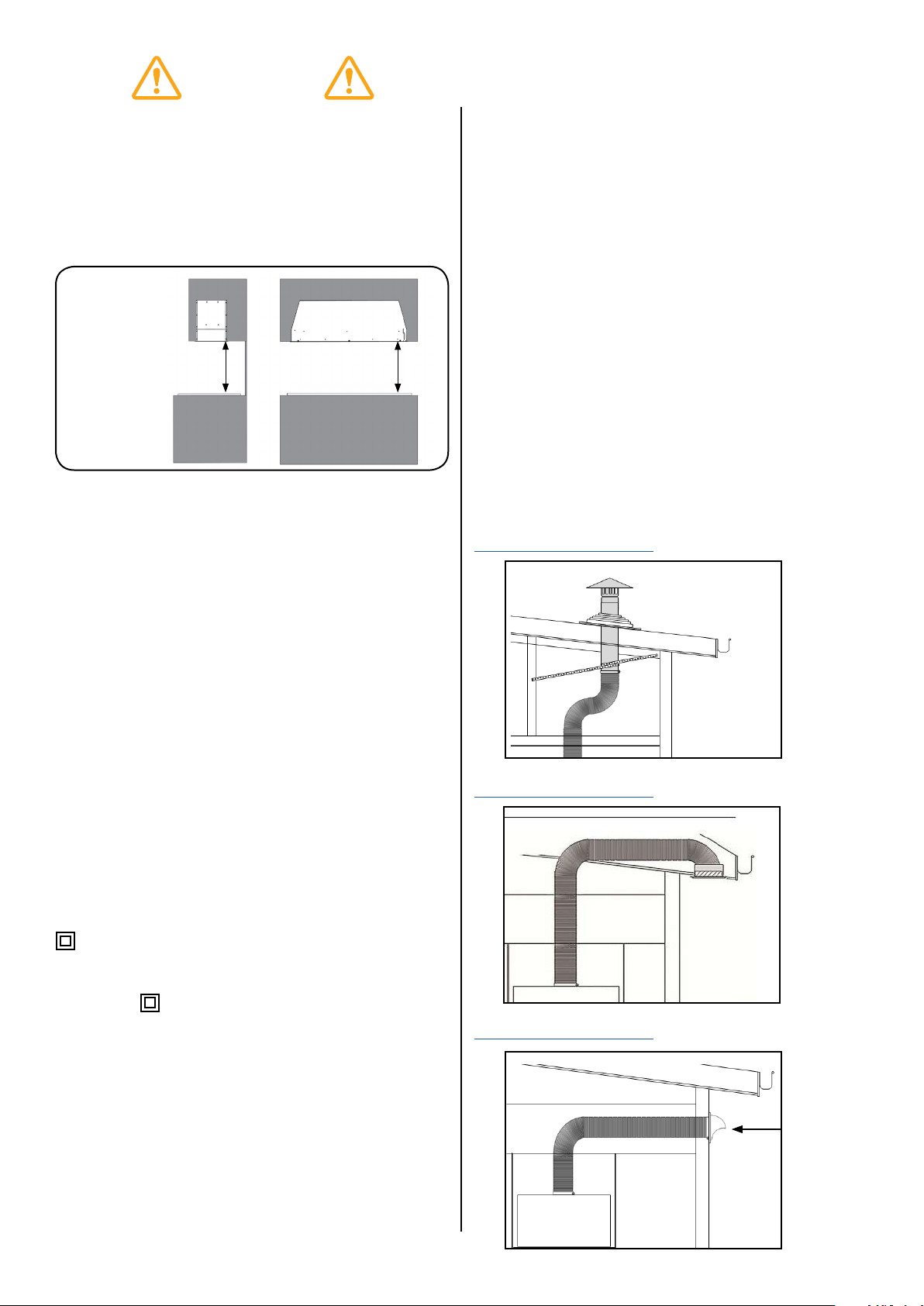
When ducting rangehood, options are as follows:
Roof vent - EASYROOF 150T/M
EASYROOF 200T/M
*Kit includes roof flashing
Download installation guide
(Fig. 2a)
Eave vent - EASYEAVE 150/200
Download installation guide
If the rating label in the rangehood shows the symbol
, the appliance is built in class II° and it does not
need any earth connection.
If the rating label in the rangehood does not show
the symbol , the appliance is built in class I° and it
needs the earth connection.
When performing the electrical connections on the
appliance, please make sure that the current-tap
is provided with earth connection and that voltage
values correspond to those indicated on the label
placed inside the appliance itself.
Before carrying out any cleaning or maintaining
operations, the appliance needs to be switched off.
If the appliance is not provided with a non-separable
(Fig. 2b)
Wall vent - EASYWALL 150/200
Download installation guide
Dome
featured on
200mm kit
only
(Fig. 2c)
3
Page 4

SL906-L series INSTALLATION ONBOARD
NOTE
Before installing the appliance, make sure that
none of the parts are damaged in any way. In
case of damaged parts, contact your retailer
and do not proceed with installation. Read all
of the following instructions with care before
installing the appliance.
• Use ducting within the min/max specifications
• Limit the number of ducting bends.
• Do not make any changes in ducting diameter
(recommended constant diameter: Ø 150 mm /
Ø 200 mm or equal surface area).
Before installing the appliance - in order not to
damage the appliance itself - the metal grease filter
should be removed. These filters could be removed
by pushing the handles towards the back side of the
rangehood and pulling it downwards to unfasten it
from its slot. (Fig.3).
To install the appliance please respect the follow
instructions:
• The appliance must be installed by qualified
technicians, or where possible use a Sirius
recommended installer. See siriusbrand.com. In
order to avoid damage to the electronic parts
of the appliance, please do not use additional
screws.
• Essential precautions to respect before installing
the appliance are the following:
To have made a cutout on the bottom of the
cabinet which is suitable to hold the appliance in
position (fig. 4):
SL906 L520 - 501 x 265mm
SL906 L850 - 835 x 265mm
SL906 L EXCEL 850 - 835 x 265mm
SL906 L EXCEL 1000 - 985 x 265mm
SL906 L EXCEL 1200 - 1100 x 265mm
(Fig.3a)
(Fig.4)
1. Prepare the power supply - 240 volts.
2. Prepare a hole for the exhaust - 160mm diameter
for single motor & 210mm for for twin motor
versions.
• Maximum length of ducting should not exceed 7
metres to motor.
• (SEM 1 or SEM 8) Additional 5 metres from motor
to atmosphere.
• Do not use screws to fix the ducting to the
rangehoods as they will prevent the movement of
non-return valves.
• Limit the number of elbows in the ducting, since
each elbow reduces the duct efficiency by 1
metre. (i.e. if you use two 90° elbows, the length
of ducting must not exceed 5 metres.)
• Avoid abrupt direction changes.
• Use 150mm constant diameter ducting for the
whole length for the single motor, 200mm ducting
for the twin motor model.
• The use of Sirius ducting will increase the
warranty of the unit to 4 years.
(Fig.3b)
4
Page 5

WARNING
CAUTION
The rangehood is quite heavy, so two people
will be needed for installation.
1. To install the appliance, adjust the position of the
adjustable side-springs using the supplied screws
(fig.5), according to the thickness of the board, in
which the appliance will be fixed.
27mm
(Fig.5)
2. Insert the rangehood into the cutout in the
cabinet until the stop click of the side-springs is
heard and the rangehood is supported.
3. Insert the screws provided into the holes inside
the rangehood (Fig.6) to fix it to cabinetry.
Before connecting any ducting to the motor,
make sure the non-return valves - which are on
the air outlet of the motor - can swing open.
External venting
• Connect the flange to the exhaust hole with the
appropriate ducting. Connect the rangehood with
the electrical mains through the supply cord.
Rear vented version
• All the models with one motor can be rear
vented; if the customer wants to use this option,
it is necessary to remove the 18 screws from
the motor group support. Then take the metal
support with motor included out (fig.7a). Turn
the motor to have the air outlet on the rear side
(fig.7b) and fix the scews previously removed.
4. Insert the grease channel.
5. Insert the grease filter (Fig.3b)
(Fig.7a) (Fig.7b)
(Fig.6)
5
Page 6

SL907 700 INSTALLATION
NOTE
Before installing the appliance, make sure that
none of the parts is damaged in any way. In
case of damaged parts, contact your retailer
and do not proceed with installation. Read all
of the following instructions with care before
installing the appliance.
• Use an air outlet ducting within min/max
specifications.
• Limit the number of pipe bends. Use a material
approved by standards and regulations.
• Avoid any sudden changes in pipe section
(recommended constant diameter: Ø 150 mm.
(Fig.10)
Insert the grease filter again and close the perimeter
panel.
• The use of Sirius ducting will increase the
warranty of the unit to 4 years.
1. Before carrying out installation, please remove the
grease filter in order to avoid possible damages
to the appliance. Please follow the following steps
to remove the metal grease filter: open the light
panel first, by turning it downwards (fig.8), then
remove the grease filter.
(Fig.8)
2. Make a hole on the surface of the following
dimensions (fig.9):
SL907 700 - 270 x 680mm
(Fig.9)
3. Insert the SL907 unit, making sure the control
panel is on the right, looking at the product from
the front of the cabinetry.
4. Connect the electrical lead and connect the air
outlet flange from the unit to a suitable exhausting
duct.
5. Fix the unit by using the four screws provided and
tighten them as shown in (fig.10).
OPERATION
SL906-L series - S907 700 (fig. 11)
A: Light switch on/off
B: Motor switch on speed 1/off - (low/simmer)
C: Motor switch on speed 2 - (general cooking)
D: Motor switch on speed 3 - (high power)
E: Motor switch on speed 4 - (booster)
F: 10 minute shut-off timer
(Fig.11)
MAINTENANCE
• Accurate maintenance guarantees good
functioning and long-lasting performance.
• Particular care is due to the grease filter panel. It
can be removed by pushing its handle toward the
back side of the rangehood and pulling the filter
downwards so to unfasten it from its slot (Fig.3).
To insert the filter just perform the opposite
operation.
• After 30 hours of operation, the push button
control panel will flash, signaling the filters are due
for cleaning. Press the timer button to reset.
The grease filter needs cleaning by regular
handwashing or in dishwashers every two
months at least, depending on its use.
• To clean the appliance itself, water and detergent
are recommended, while abrasive products
should be avoided. For steel appliances
specialized detergents are recommended (please
follow the instructions indicated on the product
itself to obtain the desired results).
6
Page 7

NOTE
To remove the rangehood from the cabinet,
remove the fixing screws (fig. 6) using a
screwdriver, and remove the grease filters
(fig.3).
• Push down on the small handle of the springs,
which are inside the rangehood, with the
necessary strength to unhook the hood from the
cabinet.
WARNING
If the supply cord is damaged, it must be
replaced by the manufacturer or its service
agent or a similarly qualified person in order to
avoid a hazard.
REPLACING THE SL 907 700
FLUORESCENT LAMP
1. To replace the fluorescent lamps of SL907 model,
you need to open the perimeter panel, by rotating
it as shown in (fig.7).
2. Remove the panel fixing screws (fig.10), paying
special care in holding it during this step, then
remove the lamps and replace the damaged one
(fig. 13).
REPLACING THE LED LIGHT ON THE
SL 906-L
1. Before replacing the LED light, switch off the
rangehood, then - by using appropriate tools remove the LED light from its slot (fig.12).
2. Take out the LED light from its connector and
replace.
• To find the correct LED light, please contact Sirius
directly on our toll-free number: 1300 762 216.
(Fig.13)
3. Insert the panel again.
• If the supply cord is damaged, it must be
replaced by the manufacturer or its service agent
or a similarly qualified person in order to avoid a
hazard.
(Fig.12)
• NB: light is easier to remove from centre of
LED globe. Use a small, flathead screwdriver
(pictured), pallette knife or blunt butter knife.
7
Page 8

WIRING DIAGRAM SL906-L (1 motor)
8
Page 9

WIRING DIAGRAM SL906-L (2 motor)
9
Page 10

WIRING DIAGRAM SL907 700
10
 Loading...