

Page 1
SIR-JVC1
JVC COMPATIBLE
SIRIUS SATELLITE RADIO TUNER
Installation Guide
Page 2

Congratulations on your purchase of the SIR-JVC1– the JVC
Compatible SIRIUS Satellite Radio Tuner!
Y our new SIRIUS T uner is designed to work with JVC headunits that are
designated to be “SIRIUS READY”. Contact JVC or SIRIUS for model
compatibility.
What is SIRIUS Satellite Radio?
Over 120 channels of the best
entertainment and completely
commercial-free music for your car,
home or office.
Only SIRIUS has more than 65
original music channels, from today’s
hits to R&B oldies to classical
masterpieces. From authentic Country
and real Bluegrass to cool Jazz, hot
Latin, Reggae, Rock and many more.
Best of all, it’s all completely
commercial-free.
SIRIUS also has more than 55
channels of world-class sports, news
and entertainment. Included as part of
your subscription, you get up to 16
NFL games a week, up to 40 NBA
games a week and up to 40 NHL
games a week. (Games are
broadcasted during their respective
seasons.) Coupled with great sports
news from ESPN, the SIRIUS sports
offering is unrivaled. And don’t forget
a host of other great news and
entertainment, like NPR, CNBC, Fox
News, Radio Disney and
E! Entertainment Radio.
With SIRIUS, the emphasis is on the
music and entertainment you want.
The music is hosted by SIRIUS
Jockeys, who are true experts. They
back-up the music with compelling
information about the song being
played, and they understand that
sometimes it’s best to just let the
music speak for itself.
Rely on SIRIUS rocket science for
superior coverage.
Only SIRIUS has three powerful
satellites that fly directly over the U.S.
ensuring coast-to-coast coverage with
high elevation angles. This gives the
satellites a “clear line of sight” to your
car or home, with much less concern
for buildings, trees or other objects
that might block conventional satellite
signals.
Once you experience more than 120
channels of digital entertainment,
you’ll never want to leave your car.
For more information, visit
www.sirius.com.
2
SIR-JVC1 Installation Guide
Page 3
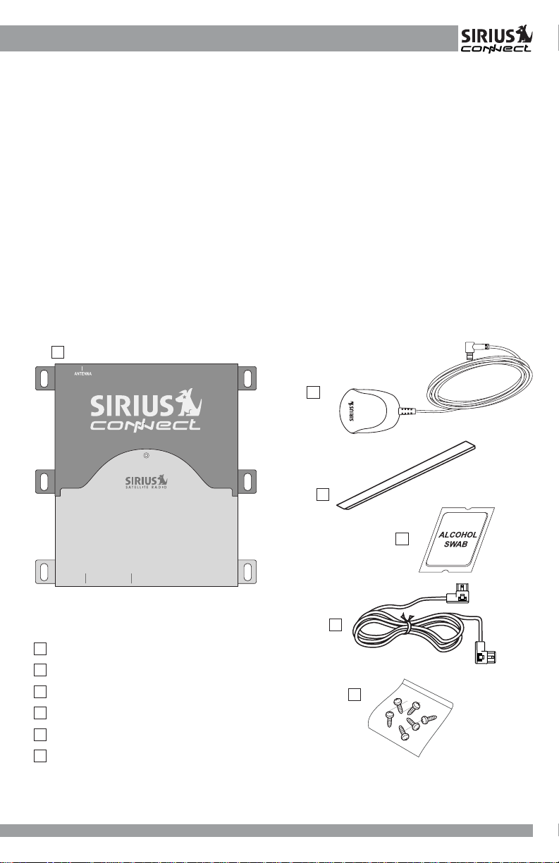
Table of Contents
Package Contents ..............................................................................................3
Warnings and Cautions ..................................................................................... 4
Installation ..........................................................................................................6
Mounting the Tuner ............................................................................................6
Installing the Antenna........................................................................................6
Optimum Antenna Mounting Locations ...........................................................7
Wiring and Cable Connections .........................................................................8
System Connection Examples........................................................................10
Activating Y our SIRIUS Subscription............................................................... 12
Specifications ................................................................................................... 13
Package Contents
A
B
C
SIR-JVC1
JVC COMPATIBLE
SIRIUS SATELLITE RADIO TUNER
HEADUNIT
CD CHANGER
A
SIR-JVC1 T uner
B
Magnetic Micro Antenna
C
Antenna Cable Cover/Tail
D
Alcohol Swab
2.5-Meter Bus Cable
E
6 Mounting Screws
F
SIR-JVC1 Operation and Installation Guide
SIR-JVC1 Installation Guide
D
E
F
3
3
Page 4

WARNING
This symbol means important
instructions. Failure to heed them
can result in serious injury or death.
DO NOT OPERATE ANY FUNCTION
THAT TAKES YOUR ATTENTION
AW A Y FROM SAFEL Y DRIVING YOUR
VEHICLE.
Any function that requires your
prolonged attention should only be
performed after coming to a complete
stop. Always stop the vehicle in a safe
location before performing these
functions.
Failure to do so may result in an
accident.
DO NOT OPEN, DISASSEMBLE OR
ALTER THE UNIT IN ANY WAY. Doing
so may result in fire, electric shock or
product damage.
DO NOT INSTALL IN LOCATIONS
THAT MIGHT HINDER VEHICLE
OPERATION. Doing so may obstruct
vision or hamper movement which can
result in a serious accident.
DO NOT INSTALL THE UNIT T O HIGH
LEVELS OF HUMIDITY, MOISTURE
OR DUST . Doing so can result in electric
shock or product failure.
FCC Warning: This equipment may
generate or use radio frequency energy .
Changes or modifications to this
equipment may cause harmful
interference unless the modifications
are expressly approved in this User
Guide. The user could lose the authority
to operate this equipment if an
unauthorized change or modification is
made.
DO NOT INSERT ANY OBJECTS INTO
THE UNIT. Doing so may result in fire,
electric shock or product damage.
USE THE CORRECT AMPERE
RATING WHEN REPLACING FUSE.
Failure to do so may result in fire,
electric shock or product damage.
MAKE THE CORRECT CONNECTIONS.
Failure to make proper connections may
result in fire or product damage.
DO NOT SPLICE INTO A ELECTRICAL
CABLES. Never cut away cable
insulation to supply power to other
equipment. Doing so will exceed the
current carrying capacity of the wire and
result in fire or electric shock.
4
Note: This equipment has been tested
and found to comply with Part 15 of the
FCC Rules. These rules are designed to
provide reasonable protection against
harmful interference. This equipment may
cause harmful interference to radio
communications if it is not installed and
used in accordance with these
instructions. However, there is no
guarantee that interference will not occur
in a particular installation. If this equipment
does cause harmful interference to radio
or television reception, which can be
determined by turning the equipment off
and on, the user is encouraged to try to
correct the interference by one of more
of the following measures:
• Relocate the receiving antenna.
• Consult the dealer or an
experienced technician for help.
SIR-JVC1 Installation Guide
Page 5

CAUTION
This symbol means important
instructions. Failure to heed them
can result in injury or material
property damage.
HALT USE IMMEDIATELY IF A
PROBLEM APPEARS. Failure to do so
may cause personal injury or damage
to the product. Return the unit to your
authorized retailer or nearest service
center for repairing.
INSTALL THE WIRING SO THAT IT IS
NOT CRIMPED OR PINCHED BY
SCREWS OR SHARP MET AL EDGES.
Route the cables away from moving parts
or sharp pointed edges. This will prevent
crimping and damage to the wiring. If the
wiring must pass through a metal hole,
be sure to use a rubber grommet to
prevent the wire’s insulation from being
cut by the metal edge of the hole.
USE THE SPECIFIED ACCESSORY
P ARTS AND INST ALL THE PRODUCT
SECURELY. Be sure to use only the
specified accessory parts. Use of nonspecified parts may damage this unit
internally or may not securely install the
unit in place. This may cause parts to
become loose, resulting in hazards or
product failure.
USE CAUTION IF YOU NEED TO
DISCONNECT THE BATTERY
TERMINAL. Please consult the
vehicle’s owner’s manual or a service
technician prior to removing the battery
positive or ground connection, as it may
cause damage to the vehicle’s electrical
system or require reprogramming of the
vehicle’s computer-controlled devices.
SIR-JVC1 Operation and Installation Guide
SIR-JVC1 Installation Guide
5
5
Page 6

Installation
It is recommended that prior to
starting the installation, you
thoroughly read this manual and
follow the guidelines listed below:
Consider the mounting location
carefully. You should make sure that
you avoid the following:
• Any location where the tuner is
exposed to moisture.
• Any location where the unit is
exposed to extreme heat.
• Any location that would interfere
with moving parts on the vehicle or
hamper driving.
Mounting the SIR-JVC1 T uner
Be sure that you find a location that is
flat and has clearance above the unit
to prevent any damage as well as
allow for ventilation.
Do not install the tuner under the
carpet or in a small enclosed area
without proper ventilation. Doing so
can result in damage to the tuner or
the vehicle.
Use the supplied screws to securely
fasten the unit.
Caution:
If you are attaching the unit directly to
the vehicle’s chassis, be sure that you
check to make sure the area behind the
unit is free from moving parts, fuel or
break lines, wire harnesses or any
other items which may get damaged by
drilling a mounting hole or using the
supplied screws.
Installing the Antenna
The antenna includes a 6-1/2” cable
cover/tail which covers the exposed
antenna cable and keeps it attached
securely to vehicle roof. The tail also
helps position the antenna the proper
distance from the window, sunroof or
rear hatch.
To attach the cover/tail:
1) Once you have determined the
proper mounting location (see next
section), clean the area with the
supplied alcohol swab.
2) Connect the cover/tail to the antenna
cable, making sure that the strainrelief on the antenna seats into the
cover/tail groove. Route the cable
through the wire channel in the cover/
tail.
Antenna
(Bottom)
Adhesive Strips
Cable Cover/Tail
Connect the cable cover/
tail to the antenna cable,
insert the cable through
the grove. Peal off the
adhesive tape
6
SIR-JVC1 Installation Guide
Page 7

3) Remove the remaining protective tape
from the adhesive, carefully position
the antenna with cover/tail and apply
pressure to secure to the vehicle.
Cable Cover/Tail
Vehicle
Optimum Antenna Mounting Locations
The optimum location to mount the
included antenna is on the roof of the
vehicle. It is important to avoid any
obstruction that will block satellite
signal – like a roof rack. For convertible
vehicles, install the antenna on the trunk
lid.
• Place the antenna on a metal
surface of your vehicle at least 12" x
12", and at least 6" from a window.
(Use the antenna cover/tail as a
guide for the proper distance).
• The antenna’s powerful magnet will
secure it to the metal surface. The
adhesive that is attached to the
antenna cover/tail will secure the
cable to the vehicle. Before routing
the antenna cable, confirm that the
antenna is mounted in a good
location.
• Route the cable from the antenna to
the vehicle’s interior by tucking it
underneath the rubber molding around
the rear window (if possible).
• Route the cable from the lowest point
of the rear window into the trunk. T ake
advantage of any existing cable
channels or wiring conduits.
SIR-JVC1 Operation and Installation Guide
SIR-JVC1 Installation Guide
• For SUVs, minivans and five-door
vehicles, bring the cable into the
vehicle under the rubber molding for
the tailgate, and continue under the
interior trim.
• From the trunk, carefully route the
cable to the location of the
SIR-JVC1 and plug the SMB
connector onto the unit.
Sedan/Coupe
SUV/Mini-Van
Truck
Convertible (only)
Caution:
• Do not pull the wire across sharp
edges that could damage it.
• Keep the wire away from areas
where it could become tangled in the
driver’s and passenger’s feet.
• Keep the antenna wire away from
extreme heat – like exhaust systems.
• A void placing the cable near any
moving parts
7
7
Page 8

Wiring and Cable Connections
Antenna Input
Connect the right-angle SMB
connector from the antenna. Push
firmly to attach.
J-BUS Output Connector
Use the supplied J-bus cable to
connect to the JVC Headunit. See
“System Connection Examples” for
more specific details.
J-BUS Input Connector
Connect to optional JVC audio
equipment like CD Changers. See
“System Connection Examples” for
more specific details.
SIR-JVC1
JVC COMPATIBLE
SIRIUS SATELLITE RADIO TUNER
HEADUNIT
CD CHANGER
A
Antenna Input (SMB)
B
J-Bus Output Connector (Headunit)
C
J-Bus Input Connector (CD Changer)
D
Power Connector
8
SIR-JVC1 Installation Guide
Page 9

Antenna (21’ cable) - Mount on
Right-angle SMB
Roof of Vehicle
Connector
SIR-JVC1
JVC COMPATIBLE
SIRIUS SATELLITE RADIO TUNER
HEADUNIT
CD CHANGER
Right-angle J-Bus
Connector
SIR-JVC1 Operation and Installation Guide
SIR-JVC1 Installation Guide
2.5-meter J-Bus Cable
(Connect to JVC SIRIUSREADY
Headunit)
9
9
Page 10

System Connection Examples
SIR-JVC1
JVC COMPATIBLE
SIRIUS SATELLITE RADIO TUNER
HEADUNIT
CD CHANGER
System 1: JVC Headunit and SIR-JVC1
10
SIR-JVC1 Installation Guide
Page 11

System 2: JVC Headunit, DVD/CD Changer and SIR-JVC1
SIR-JVC1
JVC COMPATIBLE
SIRIUS SATELLITE RADIO TUNER
HEADUNIT
CD CHANGER
SIR-JVC1 Operation and Installation Guide
SIR-JVC1 Installation Guide
11
11
Page 12

Activating Your SIRIUS Subscription
Y ou must activate SIR-JVC1 before you
can start to receive the SIRIUS Satellite
Radio broadcast.
1. Make sure that the SIR-JVC1 is
properly connected and that its
antenna is oriented to receive the
SIRIUS satellite signal.
2. Turn on the headunit.
3. Press and release the SOURCE
button on the head unit to select
SIRIUS as the source. (Each press of
the SOURCE button will change to a
different audio source.)
4. The display will read “UPDA TING” until
the SIR-JVC1 channel update is
completed. This is where the latest
channel line up is updated on the
SIRIUS Receiver.
NOTE: Don’t push any buttons or
perform any operations until
updating has been completed.
Once updated and the SIRIUS
channels are received, you will be
tuned to SIRIUS Satellite Radio’s
Preview Channel (Channel 184). Y ou
should be able to hear the SIRIUS
Preview channel’s Audio.
5. Find the SIRIUS ID (SID) of your unit.
The SID can be found on a sticker on
the bottom of the SIR-JVC1 or through
the PSM menu of your JVC headunit.
The PSM menu is typically accessed
by pressing the MENU button or
pressing and holding the SEL button,
depending on your headunit. Use the
channel keys to navigate to the SID
menu option. Refer to your headunit
documentation for more information on
how to access the PSM menu.
6. The SID will be displayed. Write
down the 12 digit SID in the location
provided on the next page for future
reference.
7. Contact SIRIUS on the Internet:
https://activate.siriusradio.com
Follow the prompts to activate your
subscription.
Y ou can also call SIRIUS toll-free at 1888-539-SIRIUS (1-888-539-7474).
You will not be able to tune to any
other channels until you activate
your SIRIUS subscription.
Basic Operation
The SIR-JVC1 SIRIUS Satellite Radio
Tuner is compatible with any JVC
headunit that is “Sirius Ready”. Consult
JVC or SIRIUS Customer Support for
more information about compatibility .
Please consult your JVC owner’s
manual for proper operation instructions
for using satellite radio products.
12
SIR-JVC1 Installation Guide
Page 13

Specifications
Operational Frequencies
Satellite ......................................................................... 2322.293/2330.207 MHz
Terrestrial....................................................................................... 2326.250MHz
Power Requirements .................................................................. 11-16 Volts DC
Chassis Size ............................. 126.75mm x 125.75mm x 34.75mm (WxHxD)
Antenna Type ................................................................................Mini-Magnetic
Antenna Cable Length ................................................. 21’ (single micro-cable)
Connector Type .....................................................................SMB (Right-angle)
Audio Interface ...........................................2 IP-Bus Connectors (Input/Output)
Audio Output ............................................................................. 1.4V rms (Fixed)
Included Cable ......................................................... 2.5 Meter Bus (Male/Male)
Please write down your SIRIUS ID in the space provided below:
SIRIUS ID:
SIRIUS Customer Service: 1-888-539-7474
SIR-JVC1 Operation and Installation Guide
SIR-JVC1 Installation Guide
13
13
Page 14

SIRIUS Satellite Radio
1221 Avenue of the Americas
New York, NY 10020
(888) 539-7474
www.sirius.com
© 2004 SIRIUS Satellite Radio Inc.
JVC-SIR-JVC1-Install-Manual-(v111004)
 Loading...