

Page 1
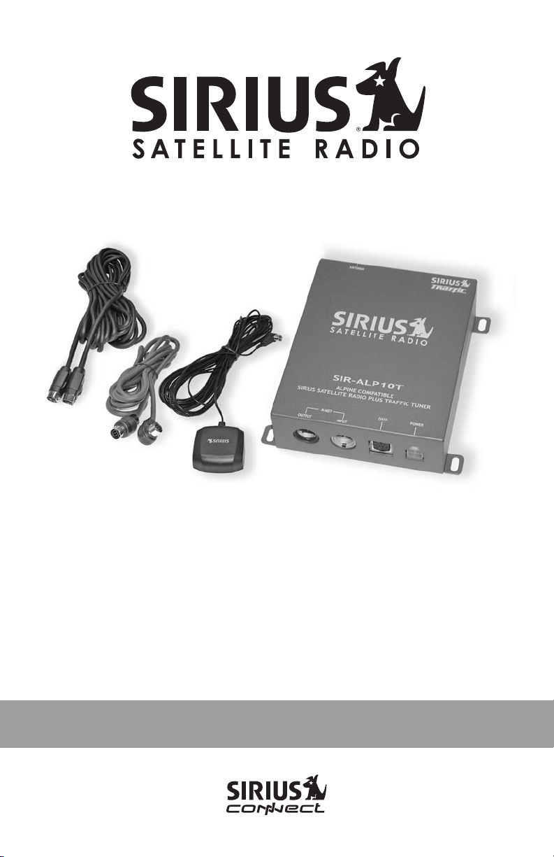
SIR-ALP10T
ALPINE COMPATIBLE
SIRIUS SATELLITE RADIO PLUS TRAFFIC TUNER
Installation Guide
Page 2

Congratulations on your purchase of the SIR-ALP10T, the
Alpine Compatible SIRIUS Satellite Radio Plus Traffic Tuner!
Your new SIRIUS Radio Plus Traffic Tuner is designed to work with compatible Alpine
satellite radio ready headunits and traffic ready navigation systems. Contact Alpine or
SIRIUS for model compatibility.
What is SIRIUS Satellite Radio?
Over 120 channels of the best
entertainment and completely
commercial-free music for your car,
home or office.
Only SIRIUS has more than 65 original
music channels, from today’s hits to R&B
oldies to classical masterpieces. From
authentic country and real bluegrass to cool
jazz, hot latin, reggae, rock and many more.
Best of all, it’s all completely commercialfree.
SIRIUS also has more than 55 channels of
world-class sports, news and
entertainment. Included as part of your
subscription, you get up to 16 NFL games a
week, up to 40 NBA games a week and up
to 40 NHL games a week. (Games are
broadcast during their respective seasons.)
Coupled with great sports news from
ESPN, the SIRIUS sports offering is
unrivaled. And don’t forget a host of other
great news and entertainment, like NPR,
CNBC, Fox News, Radio Disney and E!
Entertainment Radio. For more information,
visit www.sirius.com.
What is SIRIUS Traffic?
Navigational traffic information for 22
major metropolitan areas* in the
continental US.
SIRIUS Traffic conveys navigational traffic
information for visual display on a
compatible navigation system.
Using a navigation system (such as the
Alpine NVE-N872A), traffic data from
SIRIUS is displayed either superimposed on
a navigation map, or in a list type format
displayed on the navigation screen. The
data provides traffic speed and flow
information as well as scheduled and
unscheduled incidents, alerting you to
congestion, accidents, road construction,
detours, and other traffic related information
as you drive. The navigation system’s touch
and voice recognition controls can provide
easy access to detailed information. The
SIRIUS Traffic data is updated frequently
enabling you to be up-to-date regarding
traffic situations. Based on the information
from SIRIUS Traffic, the navigation system
can then plan alternate routes before you
get caught in traffic, and if you make a
wrong turn, the system can recalculate your
route and get you back on track in seconds.
* Metropolitan areas for which the SIRIUS Traffic service is available as of November 2005
are: Atlanta, Baltimore, Boston, Chicago, Dallas /Ft. Worth, Detroit, Houston, Los Angeles,
Miami/Ft. Lauderdale, Minneapolis/St. Paul, New York City, Orlando, Philadelphia, Phoenix,
Pittsburgh, San Francisco/Oakland, San Diego, San Jose, Seattle, St. Louis, Tampa, and
Washington, DC. Additional cities are expected to be added as they become available.
2
SIR-ALP10T Installation Guide
Page 3
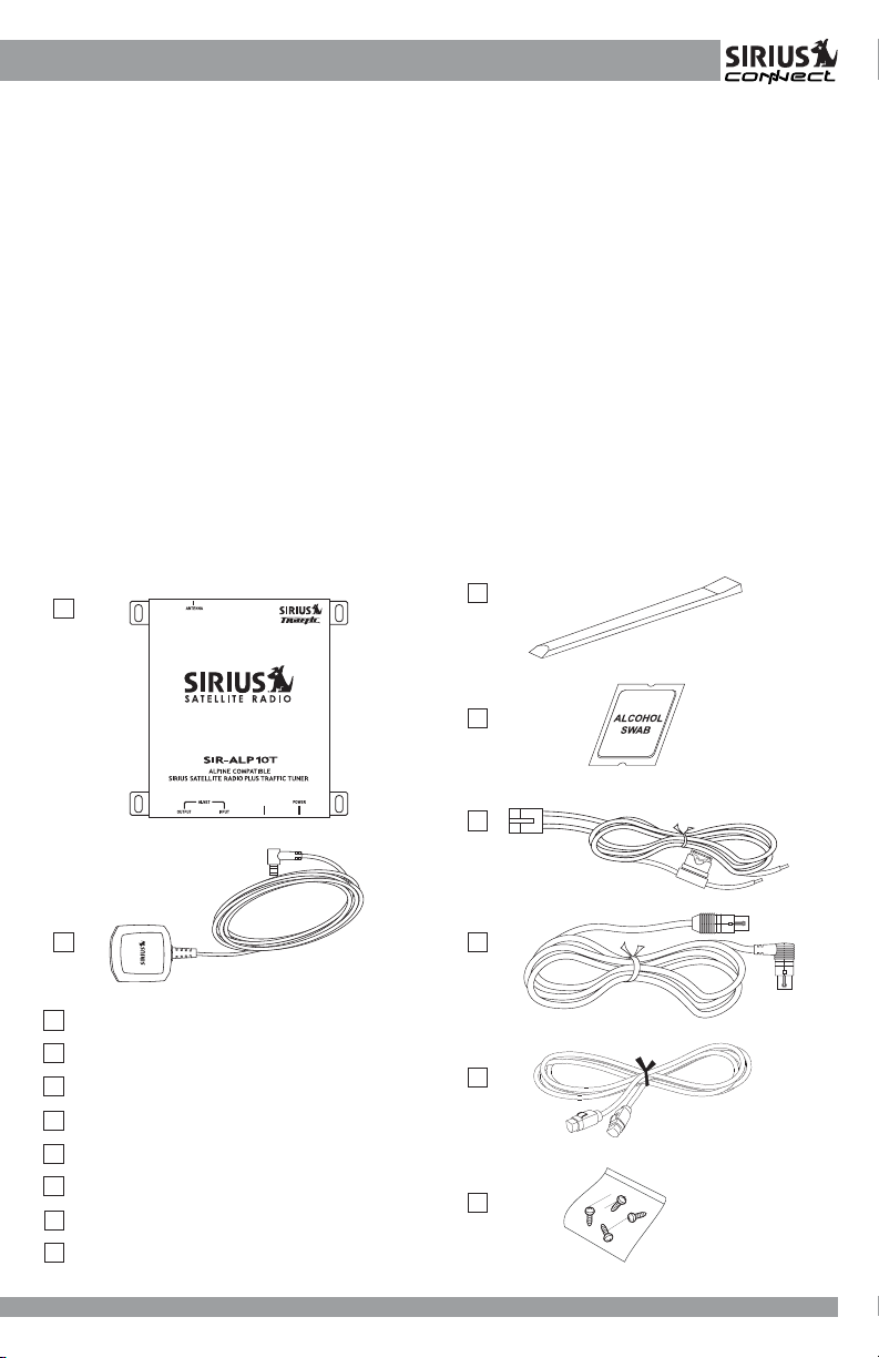
Table of Contents
Package Contents ............................................................................................................... 3
Warnings and Cautions........................................................................................................ 4
Installation ............................................................................................................................ 6
Mounting the SIR-ALP10T Tuner .......................................................................................... 6
Installing the Antenna ........................................................................................................... 6
Optimum Antenna Mounting Locations ................................................................................. 7
Wiring and Cable Connections ............................................................................................. 8
System Connection Examples ........................................................................................... 10
Activating Your SIRIUS Subscriptions ................................................................................. 15
Traffic Information Setup .................................................................................................... 17
Basic Operation .................................................................................................................19
Audio Headunit Messages .................................................................................................. 21
Navigation System Messages ............................................................................................ 21
Specifications .................................................................................................................... 22
12 Month Limited Warranty................................................................................................. 23
Package Contents
A
DATA
C
D
E
B
A
SIR-ALP10T Tuner
B
Magnetic Mini Antenna
C
Antenna Cable Cover/Tail
D
Alcohol Swab
E
Power Harness With In-Line Fuse
F
2.5-Meter Ai-NET Cable
G
3.5-Meter Data Cable
H
4 Mounting Screws
SIR-ALP10T Operation and Installation Guide
SIR-ALP10T Installation Guide
F
G
H
3
3
Page 4

WARNING
This symbol means important
instructions. Failure to heed them can
result in serious injury or death.
DO NOT OPERATE ANY FUNCTION
THAT TAKES YOUR ATTENTION AWAY
FROM SAFELY DRIVING YOUR
VEHICLE.
Any function that requires your prolonged
attention should only be performed after
coming to a complete stop. Always stop the
vehicle in a safe location before performing
these functions. Failure to do so may result
in an accident.
DO NOT OPEN, DISASSEMBLE OR
ALTER THE UNIT IN ANY WAY. Doing so
may result in fire, electric shock or product
damage.
DO NOT INSERT ANY OBJECTS INTO
THE UNIT. Doing so may result in fire,
electric shock or product damage.
USE THE CORRECT AMPERE RATING
WHEN REPLACING FUSE. Failure to do
so may result in fire, electric shock or
product damage.
MAKE THE CORRECT CONNECTIONS.
Failure to make proper connections may
result in fire or product damage.
DO NOT SPLICE INTO A ELECTRICAL
CABLES. Never cut away cable insulation
to supply power to other equipment. Doing
so will exceed the current carrying capacity
of the wire and result in fire or electric
shock.
DO NOT INSTALL IN LOCATIONS THAT
MIGHT HINDER VEHICLE OPERATION.
Doing so may obstruct vision or hamper
movement which can result in a serious
accident.
DO NOT INSTALL THE UNIT TO HIGH
LEVELS OF HUMIDITY, MOISTURE OR
DUST. Doing so can result in electric shock
or product failure.
FCC Warning: This equipment may
generate or use radio frequency energy.
Changes or modifications to this equipment
may cause harmful interference unless the
modifications are expressly approved in this
User Guide. The user could lose the
authority to operate this equipment if an
unauthorized change or modification is
made.
Note: This equipment has been tested and
found to comply with Part 15 of the FCC
Rules. These rules are designed to provide
reasonable protection against harmful
interference. This equipment may cause
harmful interference to radio
communications if it is not installed and
used in accordance with these instructions.
However, there is no guarantee that
interference will not occur in a particular
installation. If this equipment does cause
harmful interference to radio or television
reception, which can be determined by
turning the equipment off and on, the user is
encouraged to try to correct the interference
by one of more of the following measures:
• Relocate the receiving antenna.
• Consult the dealer or an experienced
technician for help.
4
SIR-ALP10T Installation Guide
Page 5
CAUTION
This symbol means important
instructions. Failure to heed them can
result in injury or material property
damage.
HALT USE IMMEDIATELY IF A PROBLEM
APPEARS. Failure to do so may cause
personal injury or damage to the product.
Return the unit to your authorized retailer or
nearest service center for repairing.
INSTALL THE WIRING SO THAT IT IS NOT
CRIMPED OR PINCHED BY SCREWS OR
SHARP METAL EDGES. Route the cables
away from moving parts or sharp pointed
edges. This will prevent crimping and
damage to the wiring. If the wiring must
pass through a metal hole, be sure to use a
rubber grommet to prevent the wire’s
insulation from being cut by the metal edge
of the hole.
USE THE SPECIFIED ACCESSORY
PARTS AND INSTALL THE PRODUCT
SECURELY. Be sure to use only the
specified accessory parts. Use of nonspecified parts may damage this unit
internally or may not securely install the unit
in place. This may cause parts to become
loose, resulting in hazards or product
failure.
USE CAUTION IF YOU NEED TO
DISCONNECT THE BATTERY TERMINAL.
Please consult the vehicle’s owner’s
manual or a service technician prior to
removing the battery positive or ground
connection, as it may cause damage to the
vehicle’s electrical system or require
reprogramming of the vehicle’s computercontrolled devices.
SIR-ALP10T Operation and Installation Guide
SIR-ALP10T Installation Guide
5
5
Page 6
Installation
It is recommended that prior to starting the
installation, you read completely this
installation manual and follow the guidelines
listed below:
Consider the mounting location carefully.
You should make sure that you avoid the
following:
• Any location where the tuner is
exposed to moisture.
• Any location where the tuner is
exposed to extreme heat.
• Any location that would interfere with
moving parts on the vehicle or interfere
with driving.
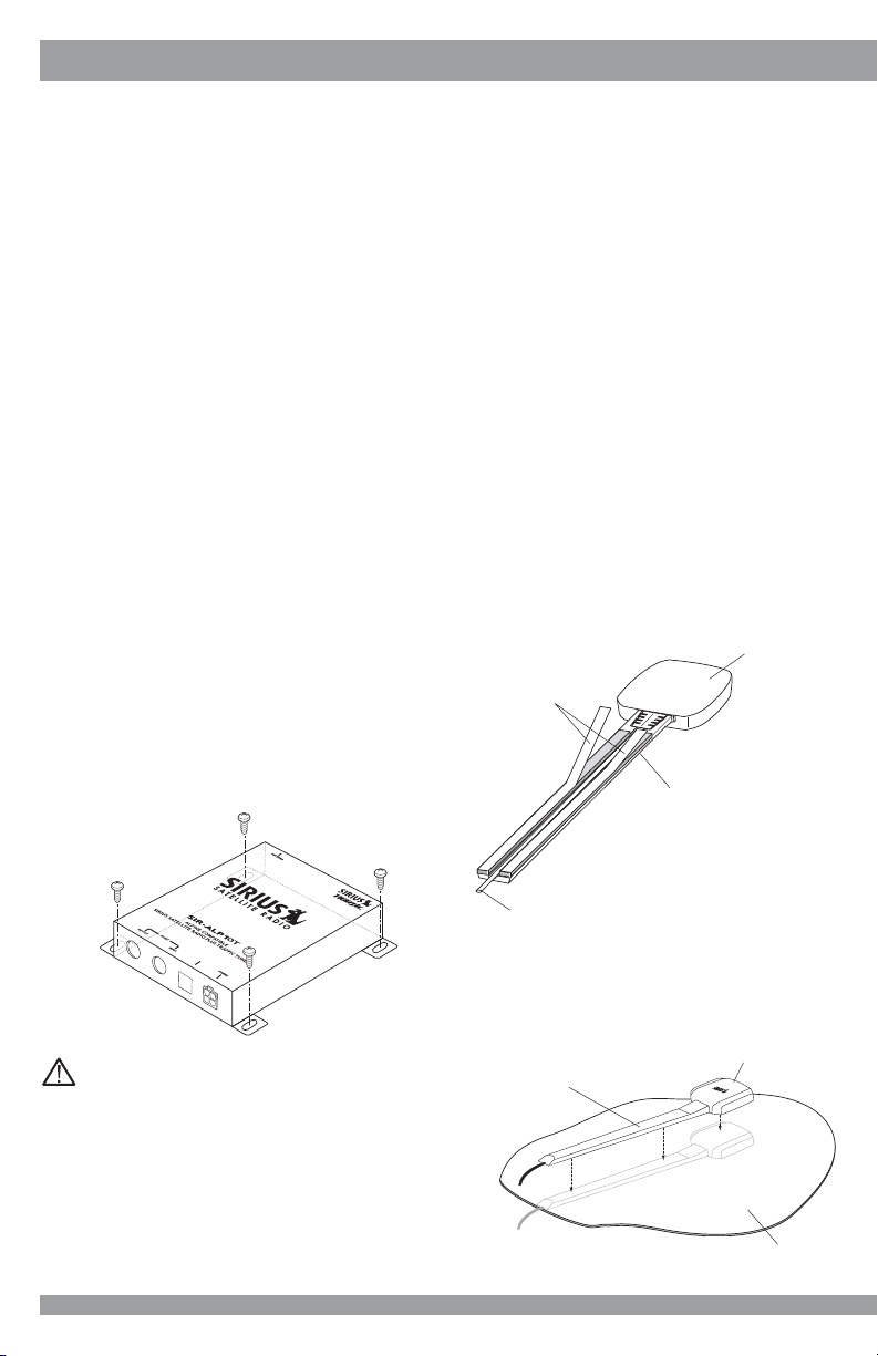
Mounting the SIR-ALP10T Tuner
Be sure that you find a location that is flat
and has clearance above the tuner to
prevent any damage, as well as allow for
ventilation.
Do not install the tuner under the carpet or
in a small enclosed area without proper
ventilation. Doing so can result in damage
to the tuner or the vehicle. Use the supplied
screws to securely fasten the unit.
Installing the Antenna
The antenna includes a plastic cable cover/
tail which covers the exposed antenna
cable and keeps it attached securely to
vehicle roof. The tail also helps position the
antenna the proper distance from the rear
window, sunroof or rear hatch.
To attach the cover/tail:
1. Once you have determined the proper
mounting location (see the next
section), clean the area with the
supplied alcohol swab.
2. Connect the antenna cover/tail to the
antenna cable, making sure that the
strain-relief on the antenna seats into
the cover/tail groove. Route the cable
through the wire channel in the cover/
tail.
Antenna
(Underside)
Adhesive Strips
D
A
T
A
Caution:
If you are attaching the tuner directly to the
vehicle’s chassis, be sure that you check to
make sure the area behind the tuner is free
from moving parts, fuel or brake lines, wire
harnesses or any other items which may
get damaged by drilling a mounting hole or
from the screws.
6
Cable
Cover/Tail
Antenna Cable
3. Remove the protective tape from the
adhesive and carefully position the
antenna with cover/tail and apply
pressure to secure it to the vehicle.
Antenna
Cable Cover/Tail
Vehicle
SIR-ALP10T Installation Guide
Page 7
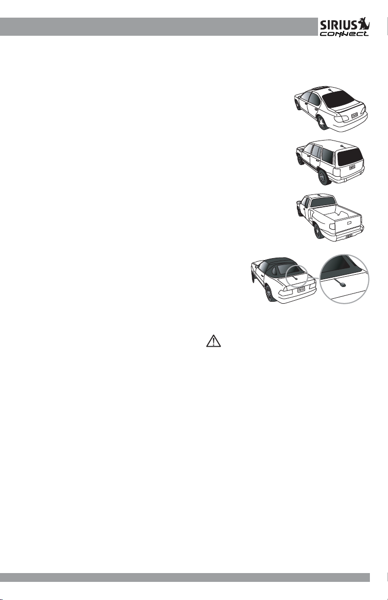
Optimum Antenna Mounting Locations
The optimum location to mount the antenna
is on the roof of the vehicle. It is important to
avoid any obstruction that will block the
satellite signal, such as a roof rack. For
convertible vehicles, install the antenna on
the trunk lid as shown.
• Place the antenna on a metal surface
of your vehicle at least 12" x 12", and at
least 6" from a window. (Use the
antenna cover/tail as a guide for the
proper distance from the rear window.)
• The antenna’s magnet will secure it to
the metal surface. The adhesive that is
attached to the antenna cover/tail will
secure the cable to the vehicle. Before
routing the antenna cable, confirm that
the antenna is mounted in a suitable
location.
• Route the cable from the antenna to the
vehicle’s interior by tucking it
underneath the rubber molding around
the rear window, if possible.
• Route the cable from the lowest point
of the rear window into the trunk. Take
advantage of any existing cable
channels or wiring conduits.
• For SUVs, minivans and five-door
vehicles, bring the cable into the
vehicle under the rubber molding of the
tailgate, and continue under the interior
trim.
• From the trunk, carefully route the
cable to the location of the
SIR-ALP10T and plug the SMB
connector into the tuner.
Sedan/Coupe
SUV/Mini-Van
Truck
Convertible (only)
Caution:
• Do not pull the wire across sharp
edges that could damage it.
• Keep the wire away from areas where it
could become tangled in the driver’s
and passenger’s feet.
• Keep the antenna wire away from
extreme heat, such as exhaust systems.
• Avoid placing the cable near any
moving parts.
SIR-ALP10T Operation and Installation Guide
SIR-ALP10T Installation Guide
7
7
Page 8
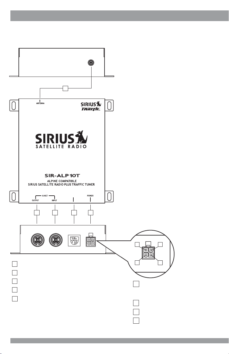
Wiring and Cable Connections
Antenna Input
Connect the right-angle SMB connector
from the antenna. Push firmly to attach.
A
DATA
B C ED
Ai-NET Output Connector
Use the supplied Ai-NET cable to connect
to the Alpine Headunit or Audio Processor –
See “System Connection Examples” for
more specific details.
Ai-NET Input Connector
Connect to optional Alpine audio equipment
like CD Changers - See “System
Connection Examples” for more specific
details.
Power Harness Connector
After the wiring connections are complete,
plug the wiring harness into the connector.
Make sure to insert firmly to lock the
connector in place.
1
2
A
Antenna Input (SMB)
B
Ai-NET Output Connector (BLACK)
C
Ai-NET Input Connector (GRAY)
D
DATA Connector (BLACK)
E
Power Connector
8
3
1
2
Battery (+)
3
Ground (-)
4
No Connection
4
ACC (Ignition Switched)
- Used in standalone navigation system
applications (no audio headunit)
SIR-ALP10T Installation Guide
Page 9

Right-angle
SMB Connector
Antenna (21’ cable)
Mount on Roof of Vehicle
Note: Connect the RED (ACC/IGN) wire
ONLY when using the SIR-ALP10T
without an Alpine headunit.
DATA
Red (Pin 1) – ACC, Connect to
Ignition Switched Circuit
Ignition
Switch
Yellow (Pin 2) – Connect to
Battery Positive (+)
Black (Pin 3) – Connect to Chassis
Ground (–)
3.5-meter Data Cable
(Connect to Alpine NVE-N872A)
2.5-meter Ai-NET Cable
(Connect to Alpine SAT Ready
Headunit or Signal Processor)
Note: It is important to follow the Input/Output configuration of the Ai-NET system. The
directionality is in reference to the Audio Path.
Gray Ai-NET connectors are Audio Input
Dark Blue Ai-NET Connectors are Audio Output. (Exception is the connector on an Alpine
Headunit – it can be either Input or Output depending on the position of the Ai-NET switch
on the bottom of the unit.
SIR-ALP10T Operation and Installation Guide
SIR-ALP10T Installation Guide
9
9
Page 10

System Connection Examples
System 1: Alpine Navigation System and SIR-ALP10T
DATA
EX-2
(REAR VIEW)
(FRONT VIEW)
Alpine Monitor System
(TME-M770 or TME-M710)
DISPLAY
Alpine Navigation System (NVE-N872A)
Note: For this system configuration, be sure to connect the RED wire on the SIR-ALP10T to a
fused ACC or IGN line.
10
SIR-ALP10T Installation Guide
Page 11

System 2: Alpine Headunit, Alpine Navigation System, and SIR-ALP10T
Alpine SAT Ready Headunit (Ai-NET CD Player or Mobile
Multimedia Station)
Special Note
Ai-NET
NORM
EQ
DIV
BOTTOM
COVER
Ai-NET Switch Set to NORM~ Default Setting.
Alpine Navigation System (NVE-N872A)
EX-2DISPLAY
DATA
(FRONT VIEW)
(REAR VIEW)
Alpine Monitor Headunit
Alpine Monitor System
(TME-M770 or TME-M710)
Note: For this system configuration, DO NOT connect the RED (ACC/IGN) line on the SIR-ALP10T.
SIR-ALP10T Operation and Installation Guide
SIR-ALP10T Installation Guide
11
11
Page 12

System Connection Examples (Continued)
System 3: Alpine Headunit, Alpine Navigation System,
CD Changer or IPOD Interface, and SIR-ALP10T
Alpine SAT Ready Headunit (Ai-NET CD Player or Mobile
Multimedia Station)
Special Note
Ai-NET
EQ
NORM
DIV
Ai-NET Switch Set to NORM~ Default Setting.
Alpine CD Changer (CHA-S634) / Alpine iPOD interface (KCA-420i)
Alpine Navigation System (NVE-N872A)
BOTTOM
COVER
EX-2DISPLAY
(FRONT VIEW)
(REAR VIEW)
DATA
Alpine Monitor Headunit
Alpine Monitor System
(TME-M770 or TME-M710)
Note: For this system configuration, DO NOT connect the RED (ACC/IGN) line on the SIR-ALP10T.
12
SIR-ALP10T Installation Guide
Page 13

System 4: Alpine Multimedia Headunit, Alpine Navigation System,
CD-Changer or IPOD Interface, and SIR-ALP10T
DATA
Alpine Multimedia Station Headunit
(IVA-D300, IVA-D310, IVA-D901)
Hideway Headunit Tuner Module
Alpine CD Changer (CHA-S634)/Alpine iPOD interface (KCA-420i)
Special Note
Bottom of
Tuner Module
NORM
Ai-NET
EQ
DIV
Ai-NET Switch Set to NORM ~ Defaut Setting
Alpine Navigation System (NVE-N872A)
EX-2DISPLAY
(FRONT VIEW)
(REAR VIEW)
Note: For this system configuration, DO NOT connect the RED (ACC/IGN) line on the SIR-ALP10T.
SIR-ALP10T Operation and Installation Guide
SIR-ALP10T Installation Guide
13
13
Page 14

System Connection Examples (Continued)
System 5: Alpine Multimedia Headunit, Alpine Navigation System,
CD-Changer or IPOD Interface, Audio Processor, and SIR-ALP10T
Alpine Multimedia Station Headunit (IVA-D300, IVA-D310, IVA-D901)
Special Note
DATA
Bottom of
Tuner Module
Headunit Input
Changer Input
Alpine Audio Processor
(PXA-H710, PXA-H700)
Hideway Headunit Tuner Module
Alpine Navigation System (NVE-N872A)
Ai-NET
EQ
NORM
DIV
Ai-NET Switch Set to EQ/DIV
(FRONT VIEW)
EX-2DISPLAY
(REAR VIEW)
Alpine CD Changer (CHA-S634)/Alpine iPOD interface (KCA-420i)
Note: For this system configuration, DO NOT connect the RED (ACC/IGN) line on the SIR-ALP10T.
14
SIR-ALP10T Installation Guide
Page 15

Activating Your SIRIUS Subscriptions
You must activate the SIR-ALP10T before
you can start to receive the SIRIUS Satellite
Radio service and the SIRIUS Traffic
service. Each is a separate service, and
each needs to be activated individually.
In order to activate your radio and traffic
subscriptions, you will need the two SIRIUS
IDs (SIDs) – one for the SIRIUS Satellite
Radio service and one for the SIRIUS Traffic
service – which uniquely identify your SIRALP10T tuner. The SIDs may be found on
sticker located on the bottom of the SIRALP10T packaging or on the bottom of the
unit itself.
The label will have printed on it two 12-digit
SID numbers. The first will be the Data SID
for the SIRIUS Traffic service, for example,
“Data SID: 123456789012”. The second is
the Audio SID for the SIRIUS Radio service,
for example, “Audio SID: 987654321098”.
Note: It is possible to activate only the
audio or the traffic service, just use the
appropriate SID. When you have located
both SIDs, write them down in the space
provided on page 22 of this manual.
Obtaining the Audio SID from the
Alpine Headunit
If you do not have access to the SID
stickers on the packaging or on the product,
you can obtain the Audio SID using the
following method.
1. Make sure that the SIR-ALP10T is
properly connected, and that the
antenna is oriented to receive the
SIRIUS satellite signal.
2. Press and release the POWER/
SOURCE button on the audio headunit
to select SIRIUS as the source. (Each
press of the button will change to a
different audio source.)
3. The display may read “UPDATING” or
“CALL 888-539-SIRIUS TO
SUBSCRIBE” until the SIR-ALP10T
channel update is completed.
NOTE: Don’t push any buttons or
perform any operations until
updating has been completed. Once
updated, and the SIRIUS channels are
being received, the display will change
to Channel 184, the SIRIUS Satellite
Radio’s Preview Channel. At this time
you should also be able to hear the
audio from the Preview Channel.
4. Use the UP/DN buttons to select
channel “255” on the display.
5. Once tuned to channel 255, the
headunit will display “SIRIUS” in the
Category Name Field, “RADIO ID” in the
Channel Field, and the Audio SID in the
Artist and Song fields of the display.
Note: You may have to press the TITLE
button on the Alpine headunit to show
the Audio SID. Be sure that the headunit
is set to Auto Scroll the text. If not, you
may only see the first eight characters
of the SID. (See your Alpine headunit
owners manual for more information.)
6. Copy the Audio SID to the space
provided on page 22 of this manual.
Obtaining the Data SID from the
Alpine NVE-N872A Navigation
System
1. Turn on the Alpine navigation system
and monitor/display.
2. The navigation system will display a
disclaimer notice. Select
proceed.
3. When the map screen is displayed,
touch the
right corner of the display screen.
menu icon in the upper
I ACCEPT
to
SIR-ALP10T Operation and Installation Guide
SIR-ALP10T Installation Guide
15
15
Page 16

4. When the Nav Menu screen is
displayed, touch the
Setup
button, or
select it by tilting the joystick to highlight
it and press the
ENTER
button.
5. When the Setup screen is displayed,
touch the
Traffic Information
selection,
or select it by tilting the joystick to
highlight it and press the
ENTER
button. Note: If the Traffic Information
selection is grayed out and cannot be
selected, this indicates that the SIRALP10T is not connected, or connected
incorrectly. Check to be sure you have
correctly installed the SIR-ALP10T
according to the instructions in this
manual.
6. The next Setup screen will display the
Data SID near the bottom of the screen
where it says
Sirius ID
. Copy the Data
SID to the space provided on page 22
of this manual.
Activating the SIRIUS Audio and/or
Data Services
1. Be sure that your Alpine headunit and
Navigation systems are turned on and
that you have the SID information
available.
2. Call SIRIUS toll-free at 1-888-539SIRIUS (1-888-539-7474) to activate
your subscriptions.
3. During the activation process, be sure
to tell the operator that have a receiver
on which you want to activate both a
SIRIUS Radio service subscription and
a SIRIUS Traffic service subscription.
Provide the operator with both the Audio
SID and the Data SID.
Once the subscription process is
completed, your audio and/or navigation
system is ready to use. Refer to the Alpine
headunit and/or navigation system owners
manuals for operation instructions.
If you have subscribed to the SIRIUS Traffic
service, proceed to the next section to
continue with the traffic information setup.
16
SIR-ALP10T Installation Guide
Page 17

Traffic Information Setup
The traffic information setup controls the
way the traffic and navigation information is
displayed. To review and/or change these
parameters:
1. Turn on the Alpine navigation system
and monitor/display.
2. The navigation system will display a
disclaimer notice. Select
proceed.
3. When the map screen is displayed,
touch the
menu icon in the upper
right corner of the display screen.
I ACCEPT
to
6. The next Setup screen will display the
system status and the traffic setup
parameters.
4. When the Nav Menu screen is
displayed, touch the
Setup
button, or
select it by tilting the joystick to highlight
it and press the
ENTER
button.
5. When the Setup screen is displayed,
touch the
Traffic Information
selection,
or select it by tilting the joystick to
highlight it and press the
ENTER
button.
SIR-ALP10T Operation and Installation Guide
SIR-ALP10T Installation Guide
The following sub-sections explain each of
the traffic information setup parameters.
System Status
System Status indicates the strength of the
SIRIUS data signal being received:
(Very Strong Signal)
(Strong Signal)
(Weak Signal)
(No Signal)
Traffic Icons
When the system receives traffic incident
information, you can choose whether to
display the traffic incident information as
icons on the map screen. Traffic incident
icons are displayed when the map scale is
set between 1/32 mile (50 m) and 5 miles
(10 km).
17
17
Page 18

To change the Traffic Icon setting, touch
Traffic Icons
joystick to highlight your selection and press
the
ENTER
Show:
are displayed on the map screen. If
selected, you may also choose the types of
traffic incidents you want to be displayed.
Hide:
on the map screen.
If
Show
traffic incident icons which are displayed:
1. Touch
joystick to highlight it and press the
ENTER
2. From the list, select (or de-select) the
types of traffic icons. Traffic incident
icon types with a checkmark next to
them will be displayed on the map.
Touch the icon type, or select (or deselect) by tilting the joystick to highlight
the selection and press the
button.
3. Selecting
traffic incident icons.
, or select it by tilting the
button.
The selected traffic incident icons
Show
is
No traffic incident icons are displayed
is selected, to change the types of
Edit
, or select it by tilting the
button.
ENTER
ALL
will choose to display all
4. When complete, touch
it by tilting the joystick to highlight it and
press the
Selecting the
display all traffic incident icons.
ENTER
Default
Done
, or select
button.
button will choose to
Traffic Speed Flow
When the system receives information
about traffic flow (congestion), you can
choose whether to display the traffic flow
information on the map screen.
Traffic flow information is displayed when
the map scale is set between 1/32 mile (50
m) and 5 miles (10 km).
To change the Traffic Speed Flow setting,
touch
Traffic Speed Flow
tilting the joystick to highlight your selection
and press the
Show:
Traffic flow information is displayed
on the map screen.
Hide:
No traffic flow information is displayed
on the map screen.
Traffic speed flow information is viewable on
the map only for those roads for which this
information is provided by the SIRIUS Traffic
service. Contact SIRIUS for updated
information on traffic flow coverage for your
area.
ENTER
, or select it by
button.
Detour Based On
When you select
Incident List screen, or press the
button on the remote control, the system
will allow you to detour your route based
Detour
in the Traffic
Detour
18
SIR-ALP10T Installation Guide
Page 19

upon the setting you have chosen, traffic or
distance.
To change the Detour Based On setting,
Basic Operation
The SIR-ALP10T SIRIUS Satellite Radio
Plus Traffic Tuner is compatible with most
Alpine satellite ready headunits from 2001
and up. The satellite traffic data is
compatible with the Alpine NVE-N872A
Navigation System. Consult the Alpine or
SIRIUS Customer Support Departments for
more information about compatibility.
For information about operating your Alpine
headunit, consult the manual which
accompanied the headunit.
The following sections describe the basic
operation of the NVE-872A Navigation
System.
touch
Detour Based On
, or select it by
tilting the joystick to highlight your selection
and press the
Traffic:
ENTER
button.
The system will provide a detour by
considering traffic congestion reported
along the route within 30 miles ahead of the
vehicle. This option should be chosen if you
plan to use the detour feature to avoid traffic
congestion.
Distance:
the system will provide a detour
by considering the distance selected by the
user.
2. When the Nav Menu screen is
displayed, touch the
Information
button,
or select it by tilting the joystick to
highlight it and press the
ENTER
button.
Traffic Incident List
If you have subscribed to the SIRIUS traffic
service, you can display the
List
screen in order to confirm traffic
information enroute to a destination, or on
roads in the vicinity of the vehicle:
1. When the map screen is displayed,
touch the
menu icon in the upper
right corner of the display screen.
SIR-ALP10T Operation and Installation Guide
SIR-ALP10T Installation Guide
Traffic Incident
19
19
Page 20

3. When the
touch the
Info
screen is displayed,
Traffic Incident List
or select it by tilting the joystick to
highlight it and press the
ENTER
button.
4. The
Traffic Incident List
screen is
displayed and provides a list of traffic
incident information in the vicinity of the
vehicle.
selection,
tilting the joystick to highlight it and
pressing the
ENTER
button) will display
a map of the area surrounding the
selected traffic incident.
Detour Button
Touching the
Detour
button, or tilting the
joystick to highlight the selection and
pressing the
ENTER
button, will cause
the system to analyze the traffic data
within 30 miles of the vehicle’s position.
If traffic congestion is found, a message
is displayed informing you of the
distance to the congestion and the
anticipated delay if the congestion is not
detoured. Note that the
on Traffic
option (described previously)
Detour Based
must be selected in the traffic setup for
this feature to work.
There are several options available to you
from this screen, which are described in the
following sections:
Traffic Incident
Touching a specific traffic incident from
the list (or selecting it by tilting the
joystick to highlight it and pressing the
ENTER
button) will display details
about the traffic incident. Note that it is
possible for the detailed information to
be identical to the summary
information.
Crosshairs Icon
Touching the crosshairs icon next to a
traffic incident entry (or selecting it by
20
To begin calculating a detour, touch
Detour
, or select it by tilting the joystick
to highlight it and press the
ENTER
button. To not plan a detour, touch the
button, or select it by tilting the
joystick to highlight it and press the
ENTER
button.
Legend Button
Touching the Legend button, or tilting
the joystick to highlight the selection
and pressing the
ENTER
button,
displays a list of the icons associated
with each incident, and defines the
meaning of each icon.
SIR-ALP10T Installation Guide
Page 21

LegendIcon
Accident
Blockage
Construction / Roadworks
Danger
Debris
Disabled Vehicle
Information
display (discussed previously), the icons
are displayed in several shapes and colors
to indicate traffic speed.
Sports Event
Traffic Jam
Weather
Viewing Traffic Speed and Flow Icon
Information
When you have set the system to display
traffic speed and flow icons on the map
Red Square
Yellow Diamond
Green Dot
Traffic incident icons and detailed
information is available for all reported
incidents.
SpeedIcon
0-10 mph
10-45 mph
45+ mph
0-20 km/h
20-90 km/h
90+ km/h
Audio Headunit Messages
These messages vary by headunit model. Consult your Alpine headunit owners manual for
more information.
LOADING - Indicates that the SIR-ALP10T is acquiring audio and/or program information.
UPDATING or CALL 1-888-CALL SIRIUS TO ACTIVATE - This message appears when
the SIR-ALP10T is receiving a subscription update or during a channel or category update.
NO SIGNAL or NO SIGNAL or ACQUIRING - Will be displayed when there is a weak or
no antenna signal present.
ANTENNA or ANTENNA ERROR - Will be displayed if the antenna is damaged or
disconnected.
Navigation System Messages
CHECK ANTENNA - The antenna is not connected to the SIR-ALP10T. Check the antenna
cable to be sure it is securely attached to the unit.
UPDATING CHANNELS - This message appears when the SIR-ALP10T is receiving
channel mapping updates.
SIR-ALP10T Operation and Installation Guide
SIR-ALP10T Installation Guide
21
21
Page 22

Specifications
Operational Frequencies
Satellite ............................................................................. 2322.293/2330.207 MHz
Terrestrial .......................................................................................... 2326.250MHz
Power Requirements ......................................................................... 8-16 Volts DC
Fuse Type .......................................................................................... 1-AMP (ATC)
Chassis Size (without Mounting Tabs) ........................ 4-1/8” x 5” x 1-3/8” (WxHxD)
105mm x 126mm x 35mm (WxHxD)
Chassis Size (with Mounting Tabs) ............................. 4-7/8” x 5” x 1-3/8” (WxHxD)
127mm x 126mm x 35mm (WxHxD)
Antenna Type .................................................................................... Mini-Magnetic
Antenna Cable Length ........................................................ 21’ (single micro-cable)
Connector Type ......................................................................... SMB (Right-angle)
Audio Interface ............................................... 2 Ai-NET Connectors (Input/Output)
Audio Output .................................................................................... 850mV (Fixed)
Weight .................................................................................... 0.528 kg. (1.16 lbs.)
Included Cables ........................................................2.5 Meter Ai-NET (Male/Male)
3.5 Meter Data Cable (Male/Male)
Note: Design and specifications are subject to change without notice.
Please write down your SIRIUS IDs in the space provided below:
SIRIUS Radio Service SID:
SIRIUS Traffic Service SID:
SIRIUS Customer Service: 1-888-539-7474
22
SIR-ALP10T Installation Guide
Page 23

12 MONTH LIMITED WARRANTY
Sirius Satellite Radio warrants to the original retail purchaser of this product that should this
product or any part thereof, under normal use and conditions, be proven defective in material
or workmanship within 12 months from the date of original purchase, such defect(s) will be
repaired or replaced with new or reconditioned product (at the Company’s option) without
charge for parts and repair labor. To obtain repair or replacement within the terms of this
Warranty, the product is to be delivered with proof of warranty coverage (e.g. dated bill of
sale), specification of defect(s), transportation prepaid, to the location shown below under
WARRANTY RETURN.
This Warranty does not extend to the elimination of externally generated static or noise, to
correction of antenna problems, to costs incurred for installation, removal or reinstallation of
the product, or to damage to tapes, compact discs, speakers, accessories, or vehicle electrical
systems.
This Warranty does not apply to any product or part thereof which, in the opinion of the Company,
has suffered or been damaged through alteration, improper installation, mishandling, misuse,
neglect, accident, or by removal or defacement of the factory serial number/bar code label(s).
THE EXTENT OF THE COMPANY’S LIABILITY UNDER THIS WARRANTY IS LIMITED TO
THE REPAIR OR REPLACEMENT PROVIDED ABOVE AND, IN NO EVENT, SHALL THE
COMPANY’S LIABILITY EXCEED THE PURCHASE PRICE PAID BY PURCHASER FOR THE
PRODUCT.
This Warranty is in lieu of all other express warranties or liabilities. ANY IMPLIED WARRANTIES,
INCLUDING ANY IMPLIED WARRANTY OF MERCHANTABILITY, SHALL BE LIMITED TO THE
DURATION OF THIS WRITTEN WARRANTY. ANY ACTION FOR BREACH OF ANY
WARRANTY HEREUNDER INCLUDING ANY IMPLIED WARRANTY OF MERCHANTABILITY
MUST BE BROUGHT WITHIN A PERIOD OF 48 MONTHS FROM DATE OF ORIGINAL
PURCHASE. IN NO CASE SHALL THE COMPANY BE LIABLE FOR ANY CONSEQUENTIAL
OR INCIDENTAL DAMAGES FOR BREACH OF THIS OR ANY OTHER WARRANTY,
EXPRESS OR IMPLIED, WHATSOEVER. No person or representative is authorized to assume
for the Company any liability other than expressed herein in connection with the sale of this
product. Some states do not allow limitations on how long an implied warranty lasts or the
exclusion or limitation of incidental or consequential damage so the above limitations or
exclusions may not apply to you. This Warranty gives you specific legal rights and you may
also have other rights which vary from state to state.
WARRANTY RETURN: To obtain repair or replacement within the terms of this Warranty,
please return product to an authorized Directed Electronics Dealer or call (800) 869-5590; proof
of purchase and description of defect are required. Products to be returned to an approved
warranty station must be shipped freight prepaid
.
SIR-ALP10T Warranty card (Sept. 2005)
SIR-ALP10T Operation and Installation Guide
SIR-ALP10T Installation Guide
23
23
Page 24

SIRIUS Satellite Radio
1221 Avenue of the Americas
New York, NY 10020
(888) 539-7474
www.sirius.com
© 2005 SIRIUS Satellite Radio Inc.
®
“SIRIUS” and the SIRIUS dog logo are registered trademarks of Sirius Satellite Radio Inc.
SIR-ALP10T Manual (102405b)
 Loading...