

Page 1
INFORMAZIONI COMMERCIALI PER I CONSUMATORI
COMMERCIAL INFORMATION FOR THE CONSUMER
INFORMATIONS COMMERCIALES POUR LE CLIENT
INFORMACIONES COMERCIALES PARA EL CLIENTE
HANDELSINFORMATIONEN FÜR DEN KUNDEN
COMMERCIËLE INFORMATIES VOOR DE KLANT
IT
ISTRUZIONI PER INSTALLAZIONE USO E MANUTENZIONE
GB
INSTALLATION, USE AND MAINTENANCE INSTRUCTION
F
INSTRUCTIONS D’UTILISATION ET AVIS DE MONTAGE
E
INSTRUCCIONES DE USO Y DE MONTAJE
D
BEDIENUNGSANLEITUNG MIT MONTAGEANWEISUNGEN
NL
GEBRUIKSAANWIJZIGING
SILT28 ROLL
SILT28 ROLL LAMP
INFORMAZIONI TECNICHE
TECHNICAL INFORMATION
INFORMATION TECHNIQUES
INFORMACIONES TÉCNICAS
TECHNISCHE INFORMATIONEN
TECHNISCHE INFORMATIES
TYPE: FSLA
Page 2

2
Page 3
IT
Il simbolo sul prodotto o sulla confezione indica che il prodotto non deve essere
considerato come un normale riuto domestico, ma deve essere portato nel punto
di raccolta appropriato per il riciclaggio di apparecchiature elettriche ed elettroniche. Provvedendo a smaltire questo prodotto in modo appropriato, si contribuisce
a evitare potenziali conseguenze negative per l’ambiente e per la salute, che potrebbero derivare da uno smaltimento inadeguato del prodotto. Per informazioni più dettagliate sul riciclaggio di questo prodotto, contattare l’ucio comunale, il servizio locale di smaltimento riuti o il negozio in cui è stato acquistato il
prodotto. Questo elettrodomestico è marcato conformemente alla Direttiva Europea 2012/19/EC sui riuti da apparecchiature elettriche ed elettroniche (WEEE).
GB
The symbol on the product or on its packaging indicates that this product may not be
treated as household waste. Instead it shall be handed over to the applicable collection
point for the recycling of electrical and electronic equipment. By ensuring this product
is disposed of correctly, you will help prevent potential negative consequences for the
environment and human health, which could otherwise be caused by inappropriate
waste handling of this product. For more detailed information about recycling of this
product, please contact your local city oce, your household waste disposal service or
the shop where you purchased the product. This appliance is marked according to the
European directive 2012/19/EC on waste electrical and electronic equipment (WEEE).
Le symbole sur le produit ou son emballage indique que ce produit ne peut être traité
F
comme déchet ménager. Il doit plutôt être remis au point de ramassage concerné, se
chargeant du recyclage du matériel électrique et électronique. En vous assurant que
ce produit est éliminé correctement, vous favorisez la prévention des conséquences
négatives pour l’environnement et la santé humaine qui, sinon, seraient le résultat
d’un traitement inapproprié des déchets de ce produit. Pour obtenir plus de détails sur
le recyclage de ce produit, veuillez prendre contact avec le bureau municipal de votre
région, votre service d’élimination des déchets ménagers ou le magasin où vous avez
acheté le produit. Cet appareil est commercialisé en accord avec la directive européenne 2012/19/EC sur les dèchets del équipments èlectriques et èlctroniques (WEEE).
El símbolo en el producto o en su embalaje indica que este producto no se pue-
E
de tratar como desperdicios normales del hogar. Este producto se debe entregar al
punto de recolección de equipos eléctricos y electrónicos para reciclaje. Al asegurarse de que este producto se deseche correctamente, usted ayudará a evitar posibles
consecuencias negativas para el ambiente y la salud pública, lo cual podría ocurrir
si este producto no se manipula de forma adecuada. Para obtener información más
detallada sobre el reciclaje de este producto, póngase en contacto con la administración de su ciudad, con su servicio de desechos del hogar o con la tienda donde
compró el producto. Este electrodomestico està marcado conforme a la directiva Europea 2012/19/EC sobre los residuos de aparatos elèctricos y electrònicos (WEEE).
3
Page 4
Das Symbol auf dem Produkt oder seiner Verpackung weist darauf hin, dass dieses
D
Produkt nicht als normaler Haushaltsabfall zu behandeln ist, sondern an einem Sammelpunkt für das Recycling von elektrischen und elektronischen Geräten abgegeben
werden muss. Durch Ihren Beitrag zum korrekten Entsorgen dieses Produkts schützen
Sie die Umwelt und die Gesundheit Ihrer Mitmenschen. Umwelt und Gesundheit werden durch falsches Entsorgen gefährdet. Weitere Informationen über das Recycling
dieses Produkts erhalten Sie von Ihrem Rathaus, Ihrer Müllabfuhr oder dem Geschäft,
in dem Sie das Produkt gekauft haben. Dieses Elektrohaushaltsgerät ist entsprechend der EU-Richtlinie 2012/19/EC Über Elektro- und Elektronik – Altgeräte (WEEE).
NL
Het symbool op het product of op de verpakking wijst erop dat dit product niet
als huishoudafval mag worden behandeld. Het moet echter naar een plaats worden gebracht waar elektrische en elektronische apparatuur wordt gerecycled. Als
u ervoor zorgt dat dit product op de correcte manier wordt verwijderd, voorkomt
u mogelijk voor mens en milieu negatieve gevolgen die zich zouden kunnen voordoen in geval van verkeerde afvalbehandeling. Voor meer details in verband
met het recyclen van dit product, neemt u het best contact op met de gemeentelijke instanties, het bedrijf of de dienst belast met de verwijdering van huishoudafval of de winkel waar u het product hebt gekocht. Dit apparrat voldoet aan de
Europese richtlijnen 2012/19/EC voor elektrische en elektronische afval (WEEE).
4
Page 5

Avvertenze
Versioni d’uso
Disegno esploso
Installazione
Funzionamento
Manutenzione
INDICE
5IT6
Page 6
AVVERTENZE
* Per l’installazione del prodotto sono richieste due persone.
La distanza minima tra la supercie del
piano di cottura e la parte inferiore della
cappa deve essere superiore a 65 cm.
* I bambini e le persone inesperte o i disabili possono utilizzare l’apparecchio solo
sotto la supervisione di adulti.
* Prevedere un’adeguata aerazione del locale quando una cappa ed apparecchi alimentati con energia diversa da quella elettrica (stufe a gas, ad olio, a carbone, ecc.),
vengono usati contemporaneamente.
* Nell’operazione di collegamento elettrico assicurarsi che la presa di corrente sia
munita di collegamento a terra e vericare
che i valori di tensione corrispondono con
quelli indicati nella targhetta all’interno
dell’apparecchio.
* Prima di procedere a qualsiasi operazione
di pulizia o manutenzione è necessario togliere l’apparecchio dalla rete elettrica.
Se l’apparecchio non è provvisto di cavo
essibile non separabile e di spina, o di altro dispositivo che assicuri la omnipolare
disinserzione dalla rete, con una distanza
di apertura dei contatti di almeno 3 mm, in
tal caso tali dispositivi di separazione dalla
rete devono essere previsti nell’installazione ssa.
Se l’apparecchio è provvisto di cavo alimentazione e di spina, deve essere posto
in modo che la spina sia accessibile.
VERSIONI D’USO
L’apparecchio può essere utilizzato solo in
versione ltrante.
Nella versione ltrante l’aria ed i vapori convogliati dall’apparecchio, vengono depurati
da un ltro antigrasso, da un ltro al carbone
e rimessi in circolazione nell’ambiente.
Mentre la versione lampada (SILT28 ROLL
LAMP).
Permette solo l’illuminazione del piano.
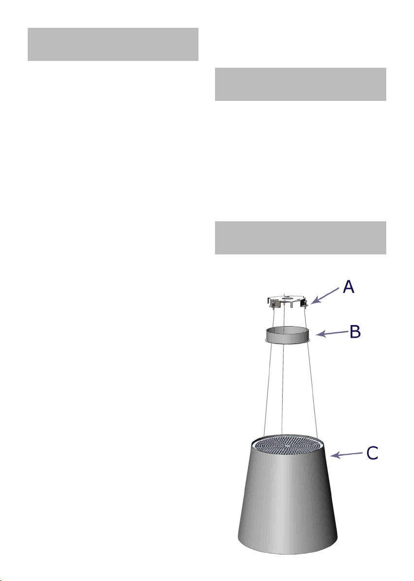
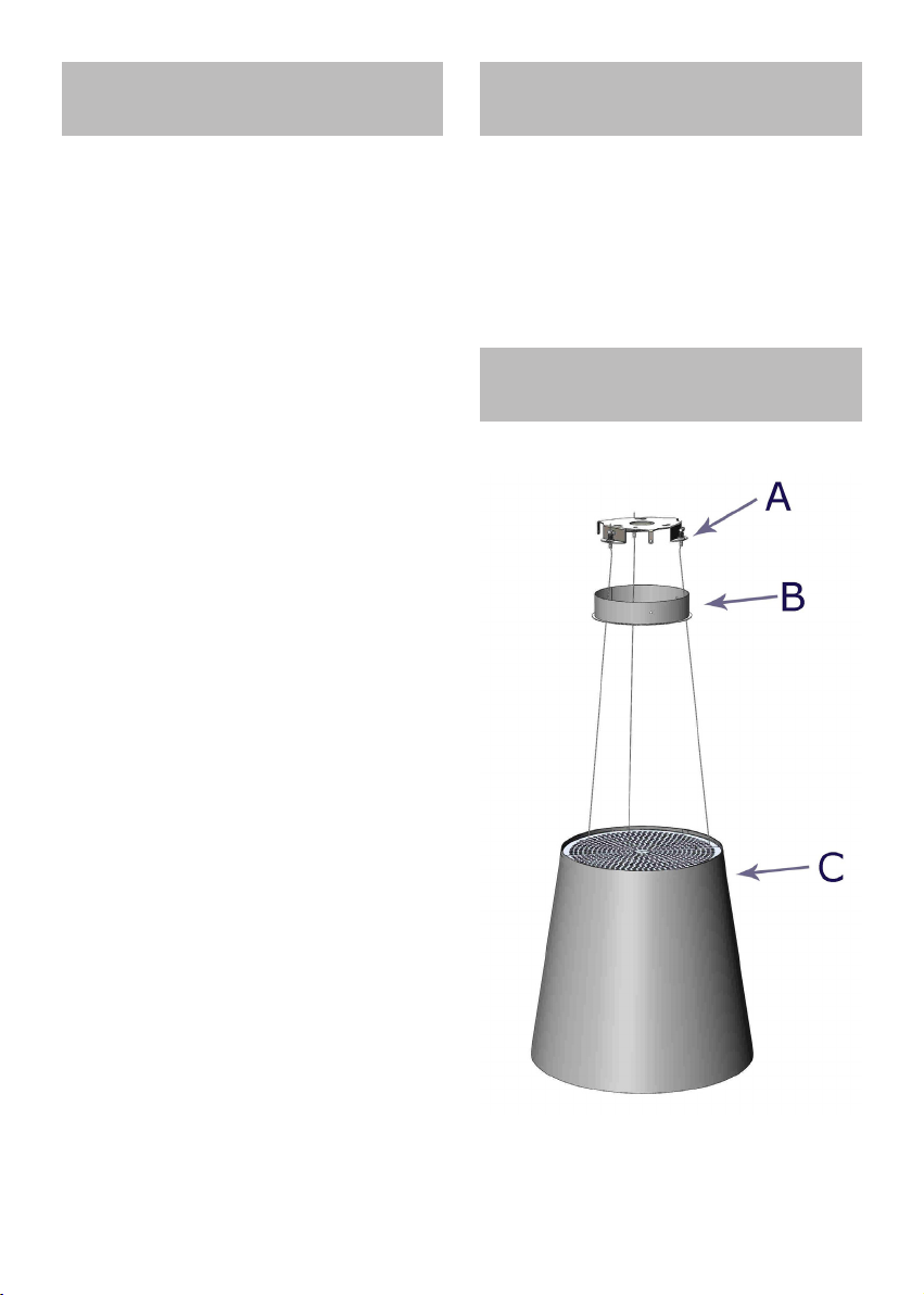
DISEGNO ESPLOSO
* Evitare l’uso di materiali che causano
ammate (ambè) nelle immediate vicinanze dell’apparecchio.
Nel caso di fritture fare particolarmente
attenzione al pericolo di incendio che costituiscono olio e grassi.
Particolarmente pericoloso per la sua inammabilità è l’olio già usato. Non usare
griglie elettriche scoperte.
Per evitare un possibile rischio d’incendio
attenersi alle istruzioni indicate per la pulizia dei ltri antigrasso e la rimozione di
eventuali depositi di grasso sull’apparecchio.
Page 7

INSTALLAZIONE
Vericare che l’imballo sia integro e all’interno tutti i componenti siano integri, in caso
contrario contattare il rivenditore e non proseguire con l’installazione.
La ditta produttrice non risponde per danni causati durante la movimentazione e
l’installazione del prodotto.
Prima di procedere all’installazione leggere attentamente tutte le istruzioni di seguito riportate.
Prelevare il prodotto dall’imballo e posizionarlo in una zona idonea, si consiglia di utilizzare del materiale morbido come spugna o
panno, su cui appoggiare il prodotto.
Prelevare dall’imballaggio la piastra di installazione (g. 1); posizionarla nel punto
prescelto del sotto, per installare la cappa,
avendo cura di mantenere il centro della piastra in corrispondenza del centro del piano
cottura.
Assicurarsi che il sotto abbia una struttura idonea a sopportare il peso del prodotto.
Tracciare le forature da realizzare, in corrispondenza delle aperture più piccole nella
piastra (g.2).
Realizzare le forature utilizzando una punta
elicoidale da diametro 8mm.
Utilizzando i tasselli in plastica e le viti in dotazione, ssare la piastra a sotto.
Prelevare dall’imballaggio la cover della piastra a sotto e passare nelle apposite forature, il cavo di alimentazione ed i tre cavi in
acciaio (g.3).
Avvicinare il prodotto alla piastra a sotto
quindi far passare i cavi in acciaio in corrispondenza degli appositi supporti come da
gura 4.
Regolare l’altezza desiderata avendo cura di
mantenere il prodotto perfettamente in piano rispetto al pavimento, procedere facendo
scorrere più o meno i cavi in acciaio all’interno del supporto, occorre svitare e spingere il
supporto per permettere lo scorrimento del
cavo, vedi g.5.
Bloccare i cavi in acciaio serrando l’apposito
supporto, avvitandolo come da g. 6.
Aggiungere i morsetti come ulteriore garanzia al bloccaggio del cavo in acciaio g. 7.
Posizionare la cover della piastra a sotto
no a coprire la piastra precedentemente ssata quindi bloccarla mediante le tre viti fornite in dotazione (g. 8).
7
Page 8
FUNZIONAMENTO
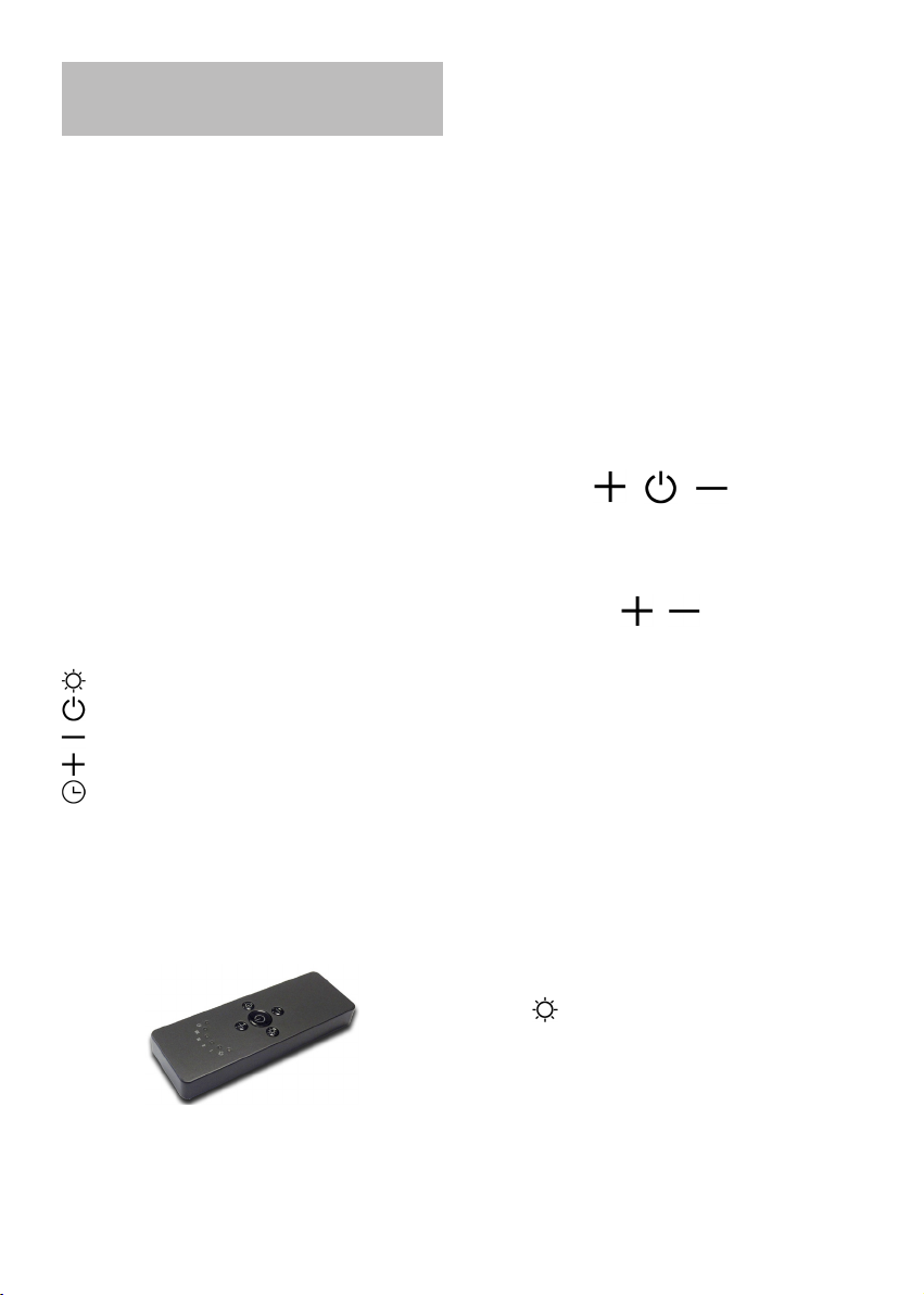
Telecomando (Fig. 11)
Alla prima accensione mantenere premuto il
tasto luce per 5 secondi.
RADIOCOMANDO SERIE
RC001
Radiocomando per il comando a distanza di
cappe aspiranti.
CARATTERISTIICHE TECNICHE
- Alimentazione pila alkalina: 12V mod.23A
- Frequenza di lavoro: 433,92 Mhz
- Combinazioni: 32.768
- Consumo max.: 25 mA
- Temperatura d’esercizio: -20 ÷ + 55 °C
- Dimensioni: 120x45x15mm.
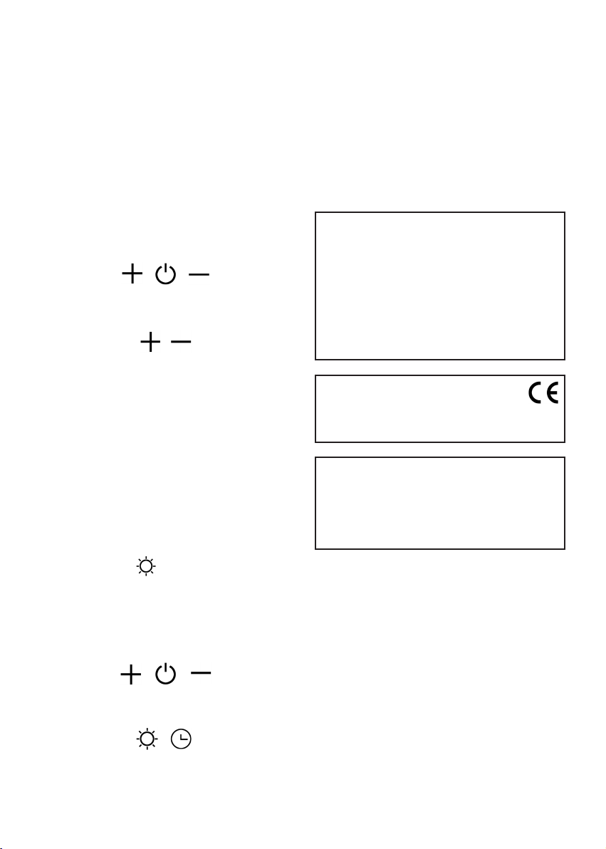
DESCRIZIONE DI FUNZIONAMENTO
Il trasmettitore è dotato di 5 tasti per la gestione del funzionamento della cappa, come
di seguito specicato:
: interruttore ON/OFF luce.
: interruttore ON (1° velocità) OFF motore.
: diminuire velocità.
: aumentare velocità.
: temporizzatore 10 minuti.
CONDIZIONE INIZIALE DI FUNZIONAMENTO
Il radiocomando viene fornito dal costruttore pronto per l’uso, contenente già dei codici
predeniti di Fabbrica.
MODALITÀ DI FUNZIONAMENTO
Congurazione standard:
La congurazione di fabbrica prevede che
tutti i sistemi “ cappa - radiocomando “ abbiano lo stesso codice di trasmissione. Nel
caso siano installati due sistemi “ cappa - radiocomando “ nello stesso locale o nelle immediate vicinanze i sistemi avendo lo stesso
codice di trasmissione potrebbero essere inuenzati quindi è necessario cambiare il codice di un solo radiocomando.
Generazione di un nuovo codice trasmissione:
Il radiocomando viene fornito dalla fabbrica
con dei codici predeniti. Se si desidera una
nuova generazione di codici, occorre eseguire la procedura nel seguente modo: premere
contemporaneamente i tasti:
in modo continuo per 2 secondi, nello stesso
istante si avrà l’accensione dei Led, successivamente premere i tasti:
(entro 5 secondi), 3 lampeggi dei Led indicheranno che l’operazione è stata completata.
ATTENZIONE! Questa operazione cancella
in maniera denitiva i codici preesistenti.
Apprendimento del nuovo codice di trasmissione: Dopo aver cambiato il codice di
trasmissione nel radiocomando, occorre far
apprendere alla centrale elettronica della
cappa aspirante il nuovo codice nel seguente
modo:
Premere il pulsante generale della cappa
(g.9), ripristinare l’alimentazione alla centrale elettronica, da questo momento ci sono
15 secondi di tempo per premere il tasto
Luce: per far sì che la centrale si sincronizzi con il nuovo codice.
8
Page 9
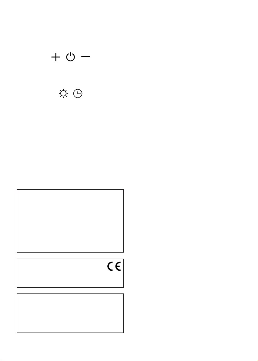
Ripristino della congurazione di Fabbrica:
Se si desidera ripristinare la congurazione
di Fabbrica, occorre eseguire la procedura nel
seguente modo: premere contemporaneamente i tasti:
in modo continuo per 2 secondi, nello stesso
istante si avrà l’accensione dei Led, successivamente premere i tasti:
(entro 5 secondi), 6 lampeggi dei Led indicheranno che l’operazione è stata completata.
ATTENZIONE! Questa operazione cancella
in maniera denitiva i codici preesistenti.
Tasto d’emergenza:
In caso di non funzionamento del radiocomando, per lo spegnimento dell’apparecchiatura, intervenire sul tasto d’emergenza.
Dopo eventuali riparazioni, ripristi- nare il
tasto d’emergenza.
ATTENZIONE
La batteria deve essere sostituita ogni
anno per garantire la portata ottimale del
trasmettitore.
Per sostituire la batteria scarica rimuovere
il coperchio di plastica, togliere la batteria
in uso e inserirne una nuova rispettando la
polarità indicata nel contenitore.
La batteria usata deve essere smaltita negli appositi raccoglitori.
Il prodotto è dotato di un dispositivo elettronico che permette lo spegnimento automatico dopo quattro ore di funzionamento
dall’ultima operazione eseguita.
TEMPORIZZAZIONI
Con l’entrata in vigore dal 1° Gennaio 2015
dei nuovi regolamenti della Commissione
Europea EU65 “Energy label” e EU66 “ Ecodesign”, abbiamo reso conforme i prodotti in
base ai requisiti richiesti.
Tutti i modelli nelle versioni energy label dispongono di una elettronica, con funzioni di
temporizzazione delle velocità di aspirazione, superiore a 650m³/h.
In eetti i modelli con motore a bordo, con
portata massima superiore a 650m³/h, prevedono la IVa velocità temporizzata dopo 5
minuti di funzionamento, Trascorsi i tempi di
cui sopra il motore di aspirazione passa alla
IIIa velocità in maniera automatica.
I prodotti in versione external motor, vengono abbinati soltanto con motori remoti dove,
come per la versione con motore a bordo,
vengono temporizzate le velocità con portate
superiori a 650m³/h. (Vedi istruzioni riportate nei motori remoti).
I motori remoti, che hanno una portata superiore a 650m³/h sia alla IVa che alla IIIa velocità, vengono automaticamente temporizzate
come segue: dalla IVa velocità, dopo 6 minuti
di funzionamento passa automaticamente
alla II velocità.
Se il prodotto viene impostato alla IIIa velocità, passa automaticamente alla II velocità
dopo 7 minuti. Resta comunque possibile
modicare le velocità in uso.
Il prodotto in modalità stand-by ha un consumo inferiore a 0.5W.
Il prodotto
Radiocomando RC001
è conforme alle speciche della Direttiva
R&TTE 99/5/EC.
AVVERTENZE
Cambiamenti o modiche non espressamente approvate dal detentore del certicato di compatibilità alle norme possono
invalidare il diritto dell’utente all’utilizzo
dell’apparecchiatura
Rev. 0 26/08/14
9
Page 10

MANUTENZIONE
Un’accurata manutenzione garantisce un
buon funzionamento ed un buon rendimento
nel tempo.
* Una cura particolare va rivolta al ltro antigrasso.
Ruotare il pannello inferiore del prodotto
facendo forza sul pomello laterale (vedi dis.
10).
Rimuovere il ltro antigrasso agendo sull’apposita maniglia.
Dopo le operazioni di pulizia o sostituzione
ripristinare il ltro antigrasso e chiudere il
pannello inferiore aperto in precedenza.
La sostituzione del ltro al carbone avviene
in rapporto all’uso, almeno una volta ogni sei
mesi.
Per la pulizia dell’apparecchio stesso viene
consigliato l’uso di acqua tiepida e detersivo
neutro, evitando l’uso di prodotti contenenti
abrasivi.
La sostituzione del cavo alimentazione deve
essere eseguita esclusivamente da personale
autorizzato.
Sostituzione della circolina uorescente.
Ruotare il pannello inferiore del prodotto facendo forza sul pomello laterale (vedi dis.
9-10).
Rimuovere le viti di chiusura del pannello e
aprirlo, sostituire la lampada uorescente
quindi ripristinare il pannello.
10
Page 11

CONTENTS
Warnings
Uses
Technical sketch
Installation
Working
Maintenance
11GB12
Page 12
WARNINGS
USES
The cooker surface and the inferior part of
the cooker hood must be at a minimum distance of 65 cm.
* The appliance is not intended for use by
young children or inrm persons without
supervision. Young children should be supervised to ensure they do not play with the
appliance.
* When performing the electrical connections on the appliance, please make sure
that them current-tap is provided with
earth connection and that voltage values
correspond to those indicated on the label
placed inside the appliance itself.
* Please disconnect the appliance from power mains, before carrying out any cleaning
or maintenance operation.
If the appliance is not equipped with a nonseparable exible cable and plug, or with
another device ensuring omnipolar disconnection from the mains, with an opening
distance between the contacts of at least 3
mm, then such disconnecting devices must
be provided in the xed installation.
If the appliance is equipped with a power
cord and a plug, it shall be placed in such
a way that the plug can be reached easily.
The appliance can be arranged only for ltering performances. In its ltering version the
air and fumes conveyed by the appliance are
cleaned both by a grease lter and by an active coal lter, and put again into circulation.
While the lamp version (SILT28 ROLL LAMP)
only allows for hob lighting.
TECHNICAL SKETCH
* The use of materials which can burst into
ames (ambé) should be avoided in close
proximity of the appliance.
When frying, please pay particular attention
to re risk due to oil and grease.
Being highly inammable, fried oil is especially dangerous. Do not use uncovered
electric grills.
In order to avoid possible re risk, all instructions for grease-lter cleaning and for
removing eventual grease deposits should
be strictly followed.
* Two persons are needed for the installation of this product.
Page 13
INSTALLATION
WORKING
At tge beginning make sure that the package is intact and all the parts are unbroken,
otherwise stop the installation and contact
the dealer. The manufacturer is not re-
sponsible for damages caused by material
handling or product installation.
Before installing the appliance read all
these instructions carefully.
Extract the product from the packaging and
lay it on a suitable place, a soft material such
as sponge or fabric should be used to place
the product on it.
Take the mounting plate out of the packaging
(g.1); to install the hood, position it in the
desired place of the ceiling, making sure the
centre of the plate is aligned with the centre
of the hob.
Check that the ceiling structure is suitable to
bear the weight of the appliance. Mark the
holes to be drilled at the smaller openings of
the plate (g.2).
Drill the holes using an 8mm diameter twist
drill.
Fix the plate to the ceiling, by using the plastic dowels and the screws supplied with the
appliance.
Take the ceiling plate cover out of the packaging and then introduce the power cord and
the three steel wires into the holes (g.3).
Place the appliance close to the ceiling plate,
and then insert the steel wires into the specic supports, as shown in g. 4.
Adjust the hood desired height, paying attention to keeping the appliance perfectly in line
with the oor by sliding the steel wire inside the support ; you will need to loosen and
push the support in order to allow the wire to
slide, see g. 5.
Secure the steel wires by tightening the support and screwing it as shown in g.6.
Use some clamps in order to further secure
the steel wire , see g. 7.
Perform the electrical connection.
Place the ceiling plate cover in such a way as
to hide the plate previously mounted, then
secure it by using the three screws provided
(g.8).
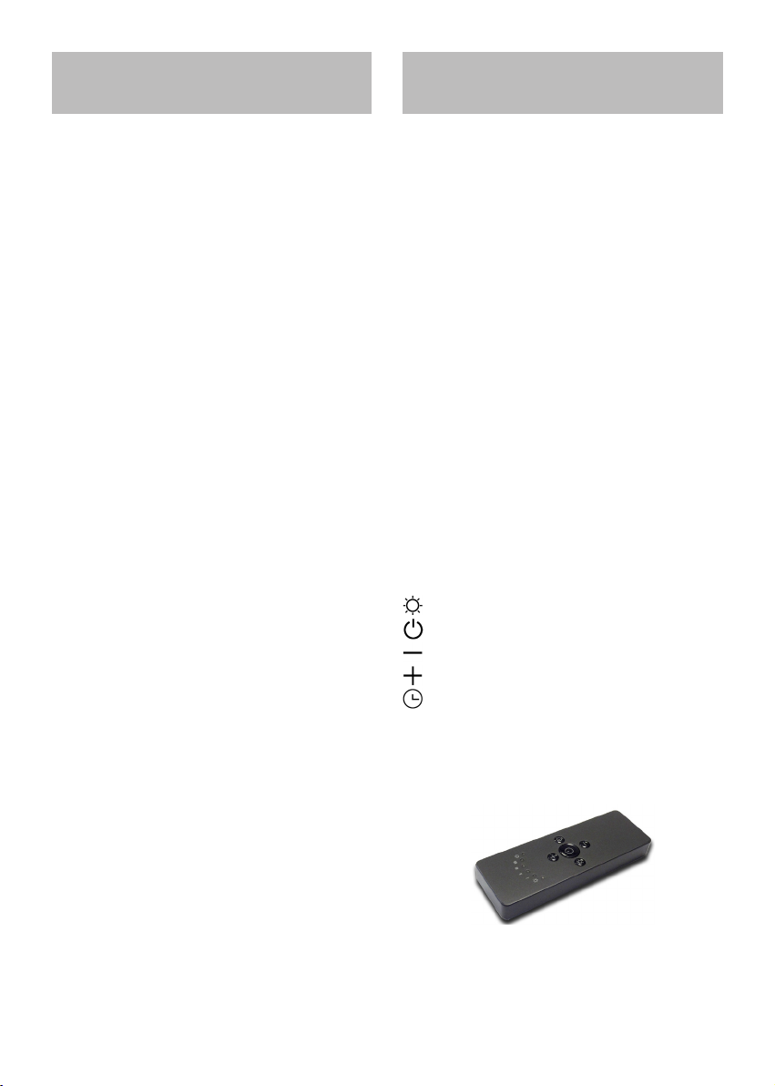
Remote control (Fig.11)
channel radio control for cooker hood remote.
At rst ignition, keep pressed the lighting
button for 5 seconds.
RC001
RADIO CONTROL
Radio control used for the remote operation
of ducted cooker hoods.
TECHNICAL DATA
- Alkaline battery powered: 12 V mod. 23 A
- Operating frequency: 433.92 Mhz
- Combinations: 32.768
- Max. consumption: 25 mA
- Operating temperature: -20 ÷ + 55 °C
- Dimensions: 120 x 45 x 15 mm.
OPERATING DESCRIPTION
The transmitter is equipped with 5 buttons
for cooker hood management, as specied
below:
: Light ON/OFF command.
: Motor ON (speed level 1) / OFF command.
: Reduce speed.
: Increase speed.
: 10-minute timer.
INITIAL OPERATING CONDITION
The manufacturer supplies the radio control
unit ready to be used with codes preset in the
Factory
13
Page 14
OPERATION MODE
Standard conguration:
Standard conguration requires all “cooker
hoods – radio control - system” to be provided with the same transmission code. In
the event two cooker hoods – radio control
system are installed in the same room or nearby, each system may aect the operation of
the another. Therefore, the code of one radio
control system must be changed.
Generatiing a new transmiissiion code:
The radio control system is provided with
preset codes. Should new codes be required, proceed as follows: Press simultaneously
buttons:
for two seconds. When Leds light on, press
buttons:
(within 5 seconds). Leds ashing 3 times indicate the procedure is completed.
WARNING! This operation deletes permanently the preset codes.
Learniing the new transmiissiion code.
Once the transmission code is changed in the
radio control unit, the electronic central unit
of the cooker hood must be made to set the
new code in the fol- lowing way:
Press the main power-o button of the hood
and then restore power to the electronic control unit. Within the next 15 seconds, press
the Liight Button to synchronise the central unit with the code.
(within 5 seconds). Leds ashing 6 times indicate the procedure is completed.
WARNING! This operation deletes permanently the preset codes.
Emergency button:
In the event that the radio control does not
work, use the emergency button to switch
the appliance o. After any necessary repairs
have been performed, reset the emergency
button.
WARNIING
The battery should be replaced every year
to guarantee the optimal range of the
transmitter.
To replace the exhausted battery, take
the plastic lid o, remove the battery and
replace it with a new one, observing the
correct battery polarities.
Used batteries should be discarded in
special collection bins.
The below product:
RC001 Radiio Controll
complies with the specications set out in
the R&TTE Directive 99/5/EC.
WARNING
Any adjustments or modications which
have not been expressly approved by the
holder of the legal conformity certicate
may invalidate the user’s rights relating to
the operation of the device.
Rev. 0 26/08/14
Reset of the Factory coniguratiion:
To restore the Factory conguration, follow
the pro- cedure described below: press simultaneously buttons:
for 2 seconds. When Leds light on, press buttons:
The products are endowed with an electronic
device which allows the automatic switching
o after 4 hours working from the last operation.
14
Page 15

TIMING
As a result of the new EU65 “Energy label” and
EU66 “ Ecodesign” regulations issued by the
European Commission, which came into force
as from January 1st, 2015 , our products have
been adapted to comply with these new requirements.
All of the models complying with the energy
label requirements, are equipped with new
electronics including a timer device for suction speeds control, when the air capacity exceeds 650m³/h.
Internal motor models, with maximum air
capacity higher than 650m³/h, are equipped with a timer device that automatically
switches the suction speed from 4th to 3rd
speed, after 5 minutes operation.
External motor models are equipped with remote motors that , as for internal motor versions, include a timer device that switches
down the suction speed when it exceeds 650
mᵌ/h. (See External Motors Instructions ).
Remote motors, whose air capacity exceeds 650m³/h at both 4th and 3rd speed, will
have the following by default timer control
functions: The suction speed is automatically switched from 4th to 2nd speed, after 6
minu tes operation.
If the appliance is working at 3rd speed, it
is automatically switched to 2nd speed, after
7 minutes operation. Operation speeds can
also be changed during operation.
The energy consumption of the appliance in
stand – by mode is lower than 0.5W.
MAINTENANCE
An accurate maintenance guarantees good
functioning and long-lasting performance.
* Particular care is due to the grease lter.
Rotate the lower panel of the appliance by
pulling the side knob (see g. 10).
Remove the grease lter by acting on the side
handle.
After cleaning or replacement operations ret the grease lter and close the lower panel
previously opened.
The active coal lter has to be replaced in relation to its use, at least once every six months. To clean the appliance itself tepid water and neutral detergent are recommended,
while abrasive products should be avoided.
The power cord must be replaced only by
qualied person.
Fluorescent circular lamp replacement
Rotate the lower panel of the appliance by
pulling the side knob (see g. 9-10).
Remove the screws found on the panel and
open it; replace the uorescent lamp and
then ret the panel.
15
Page 16

INDEX
Attention
Version de l’appareil
Détaillé
Installation
Fonctionnement
Entretien
16F17
Page 17

ATTENTION
La distance entre la surface de la table de
cuisson et la base de la hotte doit être de
65 cm au moins.
* Les enfants, les personnes dépendantes
ou handicapée ne peuvent utiliser l’appareil que si elles sont sous la surveillance
d’adultes.
* Prévoyez une aération de la pièce adéquate quand une hotte et des appareils alimentés par une énergie autre que l,énergie
électrique (poêle à gaz, à charbon, etc.) sont
utilisés en même temps.
* L’ors du raccordement électrique assurezvous que la prise de courant soit munie de mise à la terre; vériez aussi que les
valeurs de tension correspondent à celles
qui sont indiquées sur la plaque des caractéristiques de l’appareil, qui se trouve à
l’intérieur de celui-ci.
* Avant de procéder à une opération d’entretien ou de nettoyage quelconque, il faut
débrancher l’appareil.
Si votre appareil n’a pas de câble exible qui
ne peut pas être séparé, ni de prise ou bien
d’autre dispositif qui garantisse le débranchement de tous les pôles du réseau,avec
une distance d’ouverture entre les contacts
d’au moins 3 mm., ces dispositif de séparation du réseau doivent alors être prévus
dans l’installation xe.
Si l’appareille xé est pourvu du câble de
l’alimentation et une che, l’appareille doit
être placé de manière que la che soit facilement accessible.
Pour éviter des risques d’incendie possibles suivez les instructions données
concernant le nettoyage des ltres anti-graisses et sur la façon d’enlever des
dépôts éventuels de graisse sur l’appareil.
* L’installation du produit nécessite deux
personnes.
* Évitez d’utiliser des matériaux qui causent des ambées à proximité de l’appareil.
Dans le cas de fritures, faites tout particulièrement attention au danger d’incendie que représentent les huiles et les corps
gras.
A cause de son inammabilité l’huile
usagée est particulièrement dangereuse.
N’utilisez pas de grilles électriques découvertes.
Page 18

VERSIONS DE L’APPAREIL
INSTALLATION
L’appareil fonctionne seulement en version
recyclage.
Dans la version recyclage l’air et les vapeurs
aspirés par l’appareil sont épurés par un ltre
à graisse et un ltre à charbon actif et puis
remis en circulation dans la pièce.
Le modèle de la lampe (SILT28 ROLL LAMP)
permet seulement l’éclairage du plan.
DÉTAILLÉ
Vérier que l’emballage et tous les composants sont en bon état ; dans le cas contraire,
contacter le revendeur et interrompre l’installation.
Le fabriquant décline toute responsabilité
en cas de dommages causés lors de la manutention et l’installation du produit.
Avant de procéder à l’installation, veuillez
lire attentivement toutes les instructions
reportées ci-dessous.
Sortez le produit de son emballage et positionnez-le dans un endroit approprié; nous
conseillons d’utiliser un matériel doux tel
qu’une éponge ou un chion sur lequel placer le produit.
Retirez la plaque d’installation de l’emballage
(Fig. 1) ; positionnez-la à l’endroit où installer la hotte en faisant attention à ce que le
centre de la plaque correspond au centre de
la table de cuisson.
Assurez-vous que le plafond a une structure
appropriée pour supporter le poids du produit.
Tracez les trous à réaliser en correspondance des trous les plus petits de la plaque (Fig.
2). Réalisez les trous en utilisant une mèche
hélicoïdale de 8mm.
Utilisez les tasseaux en plastique et les vis
fournis pour xer la plaque au plafond.
Retirez la couverture de la plaque pour plafond de l’emballage et passez le câble d’alimentation et les trois câbles en acier par les
trous (Fig. 3).
Approchez le produit à la plaque pour plafond et passez les câbles en acier en correspondance des supports appropriés (Fig. 4).
Réglez la hauteur souhaitée en faisant attention de garder le produit parfaitement à
plat avec le sol. Faites glisser les câbles en
acier dans le support pour régler la hauteur.
D’abord il faut dévisser et pousser le support
pour permettre le glissement du câble (Fig.
5).
Bloquez les câbles en acier en vissant le support (Fig. 6).
Placez les bornes de serrage pour assurer un
blocage supplémentaire des câbles en acier
(Fig. 7).
18
Page 19

Eectuez le branchement électrique.
Placez la couverture de la plaque pour plafond en couvrant parfaitement la plaque
préalablement xée et xez-la avec les trois
vis fournies (Fig. 8).
FONCTIONNEMENT
Radiocommande (Fig. 11)
Au premier dèmarrage tenir le bouton lumière pressè pour 5 secondes.
RADIOCOMMANDE
SÉRIE BEFREE S6/S
Radiocommande pour le pilotage à distance
de hottes.
CARACTÉRIISTIIQUES TECHNIIQUES
- Alimentation par pile alcaline: 12V mod.23A
- Fréquence de travail: 433,92 Mhz
- Combinaisons: 32768
- Consommation maxi: 25 mA
- Température d’exercice: -20 ÷ + 55 °C
- Dimensions: 120x45x15 mm
DESCRIIPTIION DE FONCTIIONNEMENT
Le transmetteur est équipé de cinq touches
pour la gestion du fonctionnement de la hotte. Ces touches sont les suivantes:
: Interrupteur ON/OFF pour l’éclairage.
: Interrupteur ON (vitesse 1) /OFF pour le
moteur.
: réduire la vitesse.
: augmenter la vitesse.
: minuterie : 10 min.
CONDITION INITIALE DE FONCTIONNEMENT
La radiocommande est livrée par le fabricant
prête à l’emploi, elle contient déjà les codes
prédénis par l’usine.
19
Page 20

MODE DE FONCTIIONNEMENT
Coniguratiion standard:
La conguration d’usine prévoit que tous les
systèmes “ hotte - radiocommande “ aient le
même code de transmission. Si deux systèmes “hotte – radiocom- mande” sont installés
dans la même pièce ou à proximité des systèmes ayant le même code de transmission, ils
pourraient être inuencés et il faudrait changer le code d’une seule radiocommande.
for 2 seconds. When Leds light on, press buttons:
(within 5 seconds). Leds ashing 6 times indicate the procedure is completed.
WARNING! This operation deletes permanently the preset codes.
Generatiing a new transmiissiion code:
The radio control system is provided with
preset codes. Should new codes be required, proceed as follows: Press simultaneously
buttons:
for two seconds. When Leds light on, press
buttons:
(within 5 seconds). Leds ashing 3 times indicate
the procedure is completed.
WARNING! This operation deletes permanently the preset codes.
Learniing the new transmiissiion code:
Once the transmission code is changed in the
radio control unit, the electronic central unit
of the cooker hood must be made to set the
new code in the fol- lowing way:
Press the main power-o button of the hood
and then restore power to the electronic control unit. Within the next 15 seconds, press
the Liight Button to synchronise the central unit with the code.
Reset of the Factory coniguratiion:
To restore the Factory conguration, follow
the pro- cedure described below: press simultaneously buttons:
Emergency button:
In the event that the radio control does not
work, use the emergency button to switch
the appliance o. After any necessary repairs
have been performed, reset the emergency
button.
WARNIING
The battery should be replaced every year
to guarantee the optimal range of the
transmitter.
To replace the exhausted battery, take
the plastic lid o, remove the battery and
replace it with a new one, observing the
correct battery polarities.
Used batteries should be discarded in
special collection bins.
The below product:
RC001 Radiio Controll
complies with the specications set out in
the R&TTE Directive 99/5/EC.
WARNING
Any adjustments or modications which
have not been expressly approved by the
holder of the legal conformity certicate
may invalidate the user’s rights relating to
the operation of the device.
Rev. 0 26/08/14
The products are endowed with an electronic
device which allows the automatic switching
o after 4 hours working from the last operation.
20
Page 21

TEMPORISATEUR
Nos produits ont été adaptés pour se conformer aux nouvelles normes de l’Union Européenne en matière de l’EU65 « ÉtiquetteÉnergie » et l’EU66 « Écoconception » (à partir
du 1er janvier 2015).
La nouvelle électronique des produits ayant
l’ « Étiquette-Énergie » sont pourvus d’un
dispositif de temporisation pour le contrôle
de la vitesse d’aspiration si le débit d’air en
évacuation dépasse les 650m³/h.
En eet, les modèles avec moteur intégré
ayant un débit d’air en évacuation supérieur à
650m³/h sont pourvus d’un dispositif qui
réduit automatiquement la vitesse IV à la vitesse III après 5 minutes de fonctionnement.
Les modèles avec moteur extérieur (combiné
seulement avec des moteurs à distance comme pour les modèles avec moteur intégré)
sont pourvus d’un dispositif qui réduit la vitesse si le débit d’air en évacuation dépasse
les 650m³/h. (Voir section « Moteurs à distance »).
Les moteurs extérieurs ayant un débit d’air
en évacuation supérieur à 650m³/h à la vitesse IV et III sont temporisés comme suit :
Automatiquement de la vitesse IV à la vitesse
II après 6 minutes de fonctionnement.
Si l’appareil est réglé à la vitesse III, il passe automatiquement à la vitesse II après 7
minutes de fonctionnement. De toute façon
il est possible de modier la vitesse lors du
fonctionnement.
La consommation de appareil en mode veille
est inférieure à 0.5 W.
ENTRETIEN
Un entretien soigné est une garantie de bon
fonctionnement et de bon rendement de votre appareil dans le temps.
* Un soin particulier doit être apporté aux ltres à graisse.
Pivotez le panneau de dessous en tirant le
pommeau latéral (voir dessin 10).
Enlevez le ltre à graisse par sa poignée.
Après toute opération de nettoyage ou de
replacement, fermez le panneau de dessous
ouvert préalablement.
Le remplacement du ltre à charbon se fait en
fonction de son utilisation, au moins une fois
tous les 6 mois. Nettoyez l’appareil avec de
l’eau tiède et un produit de nettoyage neutre,
en évitant tout produit contenant des abrasifs.
Le remplacement du câble d’alimentation
doit être eectué exclusivement par un personnel autorisé.
Remplacement de la circline uorescente
Pivotez le panneau de dessous en tirant le
pommeau latéral (voir dessins 9-10).
Enlevez les vis de xation du panneau et
ouvrez-le, remplacez la circline uorescente,
puis remontez le panneau.
21
Page 22

Advertencias
Versiones
Piezas
Instalacion
Funcionamiento
Mantenimiento
ÍNDICE
22E23
Page 23

ADVERTENCIAS
* La distancia mínima entre el plano de cocción y la parte inferior de la campana debe
ser de 65 cm.
* Los niños y las personas incapacitadas o
minusválidas sólo deben utilizar el aparato
bajo supervisión de un adulto.
* Prever una adecuada aireación del local
cuando se estén utilizando contemporáneamente una campana y aparatos alimentados con energía diferente de la eléctrica
(estufas a gas, a aceite, a carbón, etc...).
* En el conexionado eléctrico asegurarse
que la toma de corriente esté provista de
conexión a tierra y vericar que los valores
de tensión se corresponden con los indicados en la etiqueta de características del
aparado.
* Antes de proceder a cualquier operación
de limpieza o mantenimiento es necesario
desconectar el aparato de la red.
Para evitar un posible riesgo de incendio
atenerse a las instrucciones indicadas para
la limpieza de los ltros antigrasa y la limpieza de eventuales depósitos de grasa en
el aparado.
* Para la instalación del producto se requieren dos personas.ww
Si el aparato no está provisto de cable
exible no removible y de conector, o de
otro dispositivo que asegure la desconexión omnpolar de la red con una distancia
de apertura de los contactos de al menos
3 mm. entonces este dispositivo de separación de la red debe estar previsto en la
instalación ja.
Si el aparato está provisto de cable de alimentación y de conector, el aparato debe
ser situado de forma que la clavica resulte
fácilmente aseguirle.
* Evitar el uso de materiales que causen
llamarada cerca de la campana. En el caso
de fritos prestar atención especial al peligro de incendio que conlleven el aceite y
la grasa.
Particularmente peligroso por su inamabilidad es el aceite ya usado. No utilizar
parrillas eléctricas descubiertas.
Page 24

VERSIONES
INSTALACION
El aparato se puede utilizar sólo con la
versiόn ltrante. En la versiόn ltrante el aire
y los vapores canalizados por el aparato se
purican por medio de un ltro anti grasa, de
un ltro de carbón y, se reponen nuevamente
en circulaciόn en el medio ambiente.
Mientras la versión lámpara (SILT28 ROLL
LAMP).
Permite sólo la iluminación de la placa.
PIEZAS
Asegúrese de que el embalaje esté intacto y
todos los componentes en su interior estén
completos, de lo contrario contacte el distribuidor y no proceda con la instalación.
El fabricante no se hace responsable de los
daños causados durante la manipulación e
instalación del producto.
Antes de empezar con la instalaciόn, lea
con atenciόn todas las instrucciones que
se dan a continuaciόn.
Extraiga el producto del embalaje y colóquelo
en un lugar adecuado, se recomienda utilizar
materiales suaves como esponja o paño, en
donde apoyar el producto.
Quitar del embalajela placa de instalación
(g.1); colocarla en el punto elegido del techo, para la instalación de la campana, prestando atención en mantener el centro de la
plancha en correspondencia del centro de la
encimera.
Asegúrese de que el techo tenga una estructura idónea para sostener el peso del producto.
Trazar los oricios que se deberán realizar,
en correspondencia de los oricios más pequeños en la placa (g. 2)
Realizar los oricios usando una punta helicoidal de 8mm de diámetro.
Utilizar tacos de plástico y tornillos suministrados (con el producto), jar la placa al
techo.
Quitar del embalaje la tapa de la placa de techo y pasar dentro de los oricios, el cable de
alimentación y los tres cables de acero (g.3)
Acercar el producto a la placa de techo, por
lo tanto, hacer pasar los cables de acero en
correspondencia de los soportes especiales
como muestra la gura 4.
Regular la altura deseada prestando atención
que el producto esté perfectamente en posición plana respecto al suelo, proceder deslizando más o menos los cables de acero en el
interior del suporte, es necesario desenroscar
y empujar el soporte para permitir que el cable se deslice, ver g. 5.
Bloquear los cables de acero cerrando el soporte especial, enroscándolo como muestra
la g. 6.
24
Page 25

Colocar las mordazas como ulterior garantía
al bloqueo del cable de acero g. 7.
Efectuar la conexión eléctrica.
Colocar la tapa de la placa de techo hasta
cubrir la placa jada anteriormente, por lo
tanto, bloquearla a través de los tres tornillos
suministrados (con el producto) (g. 8).
FUNCIONAMIENTO
Radiocontrol (Fig.11)
A la primera ignicion mantener el buton luz
apretado por 5 segundos.
RADIOCONTROL SERIE
BEFREE S6/S
Radiocontrol para el mando a distancia de
campanas de extractoras.
CARACTERÍSTICAS TÉCNICAS
- Alimentación con batería alcalina: 12V mod.23A
- Frecuencia de trabajo: 433,92 Mhz
- Combinaciones: 32.768
- Consumo máx.: 25 mA
- Temperatura de funcionamiento: -20 ÷ + 55 °C
- Dimensiones: 120x45x15mm.
DESCRIIPCIIÓN DEL FUNCIIONAMIIENTO
El transmisor está dotado de 5 teclas para la
gestión del funcionamiento de la campana,
como se especica a continuación:
: Interruptor ON/OFF luz.
: Interruptor ON (1° velocidad) OFF motor.
: Diminuir velocidad.
: Aumentar velocidad.
: Temporizador 10 minutos.
CONDICIÓN INICIAL DE FUNCIONAMIENTO
El fabricante suministra el radiomando listo
para el uso, con los códigos predenidos de
fábrica.
25
Page 26

MODALIDAD DE FUNCIONAMIENTO
Conguración estándar:
La conguración de fábrica prevé que todos
los sistemas de “campana - radiomando”
tengan el mismo código de transmisión. Si se
instalan dos sistemas “campana - radiomando” en el mismo local o en las cercanías, los
sistemas, teniendo el mismo código de transmisión pueden ser inuenciados, por tanto,
es necesario cambiar el código de un solo radiomando.
de forma constante durante 2 segundos, en
el mismo momento se encenderán los leds,
sucesivamente presione las teclas:
(dentro de 5 segundos), 6 parpadeos de los
leds indicarán que se completó la operación.
¡ATENCIÓN! Esta operación cancela de forma denitiva los códigos ya existentes.
Generación de un nuevo código de transmisión:
El radiomando ya viene de fábrica con códigos predenidos. Si desea una nueva generación de códigos, realice el procedimiento de
la siguiente manera:
presione simultáneamente las teclas:
de forma constante durante 2 segundos, en
el mismo momento se encenderán los leds,
sucesivamente presione las teclas:
(dentro de 5 segundos), 3 parpadeos de los
leds indicarán que se completó la operación.
¡ATENCIÓN! Esta operación cancela de forma denitiva los códigos ya existentes.
Aprendizajje dell nuevo código de transmisión: Después de cambiar el código de
transmisión en el radiomando, hay que hacer
que la central electrónica aprenda el nuevo
código de la campana aspiradora, de la siguiente manera:
Presione el pulsador de apagado general de
la campana, restablezca la alimentación a la
central electrónica, a partir de este momento
tiene 15 segundos de tiempo para presionar
la tecla Luz: para que la central se sincronice con el nuevo código.
Tecla de emergencia:
En caso de no funcionamiento del radiocontrol, para el apagado del aparato, utilizar la
tecla de emergencia. Después de eventuales
reparaciones, restablecer la tecla de emergencia.
ATENCIÓN
La batería se debe sustituir cada año para
garantizar el alcance óptimo del transmisor.
Para sustituir la batería descargada quite
la tapa de plástico, luego haga lo mismo
con la batería en uso y por último introduzca una nueva respetando la polaridad
indicada.
La batería usada se debe arrojar en los
contenedores especiales.
El producto
Radiiocontroll RC001
está en conformidad con las
especicaciones de la
Directiva R&TTE 99/5/EC.
ADVERTENCIAS
Cambios o modicaciones no expresamente aprobadas por quien posee el certicado de compatibilidad a las normas,
pueden invalidar el derecho del usuario al
uso de los aparatos
Rev. 0 26/08/14
Restablleciimiiento de lla coniguraciión
de fábriica: Si desea restablecer la congura-
ción de fábrica, realice el procedimiento de la
siguiente manera: presione simultáneamente
las teclas:
Introducido en la versión están euipados con
un dispositivo electrónico que lo desconecta automáticamente después de cuatro horas
de funcionamiento detoe la última operacion
efectuada.
26
Page 27

TEMPORIZACIÓN
A partir del 1° de enero 2015, con la entrada en vigor de la nueva normativa de la Comisión Europea EU65 “Energy label” y EU66
“ Ecodesign”, hemos adaptado los productos
conforme a los requisitos establecidos.
Todos los modelos con versión “Energy label”
disponen de un equipo electrónico, con funciones de temporización de la velocidad de
aspiración, superior a 650m³ / h.
De hecho, todos los modelos con motores a
bordo, con caudal máximo a 650m³ / h, disponen de la IV° velocidad temporizada tras
5 minutos de funcionamiento . Transcurrido
dicho tiempo el motor de aspiración pasa automáticamente a la III° velocidad .
Los productos en versión con motor externo,
se combinan exclusivamente con motores remotos donde, como también para la versión
con motor a bordo, se temporizan las velocidades con caudales superiores a 650m³ / h.
(Véanse las instrucciones mencionadas en los
motores remotos).
Los motores remotos, que tienen un caudal
superior a 650m³ / h , tanto en la IV° como
en la III° velocidad, se temporizan automáticamente en el siguiente modo: A partir de la
IV° velocidad , tras 6 minutos de funcionamiento pasa automáticamente a la segunda
velocidad.
Si el producto se congura en la III° velocidad, pasa automáticamente a la segunda
velocidad tras 7 minutos. Se puede también
cambiar la velocidad misma mientras se sta
usando.
El producto cuando está en modalidad “stand
by” tiene un consumo inferior a 0.5W
MANTENIMIENTO
Un correcto mantenimiento es garantía de un
buen funcionamiento y un buen rendimiento
en el tiempo. Se debe prestar particular atención al ltro anti grasa.
Girar el panel inferior del producto haciendo
fuerza sobre la manija lateral (ver dibujo 10).
Quitar el ltro anti grasa usando la manija en
cuestión.
Después de realizar la limpieza o sustitución
volver a colocar el ltro antigrasa y cerrar el
panel inferior abierto anteriormente.
La sustitución del ltro de carbón se hace
según el uso del mismo, por lo menos una
vez cada seis meses. Para la limpieza del
aparato, se recomienda utilizar agua tibia y
detergente neutro, evitando el uso de productos abrasivos.
El cambio del cable de alimentación tiene que
ser realizado únicamente por el personal autorizado.
Sustitución del tubo uorescente circular.
Girar el panel inferior del producto haciendo fuerza sobre la manija lateral (ver dibujos
9- 10).
Quitar los tornillos que cerraban el panel y
abrirlo, sustituir la lámpara uorescente y
volver a colocar el panel.
27
Page 28

INHALTSVERZEICHNIS
Allgemeine Sicherheitshinweise
Allgemeine Montagehinweise
Explosions
Geräteausführung
Installation und Montage
Schaltung des Geräts
Wartung
28D29
Page 29

ALLGEMEINE
SICHERHEITSHINWEISE
Das Gerät ist so zu montieren, dass der Abstand zwischen den Kochplatten und dem
unteren Rand der Dunstabzugshaube mindestens 65 cm beträgt.
* Kinder, hilose oder behinderte Personen
dürfen das Gerät nur unter Aufsicht von Erwachsenen betreiben.
* Bei gleichzeitigem Betrieb einer AbluftDunstabzugshaube und einer raumluftabhängigen Feuerstätte (wie z.B. gas-,
öl- oder kohlebetriebene Heizgeräte, Durchlauferhitzer,
Warmwasserbereiter) ist Vorsicht geboten,
da beim Absaugen der Luft durch die Dunstabzugshaube dem Aufstellraum die Luft
entnommen wird, die die Feuerstätte zur
Verbrennung benötigt. Ein gefahrloser Betrieb ist möglich, wenn bei gleichzeitigem
Betrieb von Haube und raumluft-abhängiger Feuerstätte im Aufstellraum der Feuerstätte ein Unterdruck von höchstens 0,04
mbar erreicht wird und damit ein Rücksaugen der Feuerstättenabgase vermieden
wird. Daher sollte der Raum mit Lüftungsklappen, die eine konstante Lüftung ausüben, versehen sein.
* Materialen, die Stichammen verursachen (ambiert) sollten nicht in unmittelbarer Nähe des Geräts stehen.
Vorsicht, beim Frittieren können Öl und
Fett in Brand raten.
Insbesondere ist gebrauchtes Öl sehr feuergefährlich.
Keine abgedeckten Elektro-Grillroste verwenden. Gegen Brenngefahr sich bitte an
die angegebenen Anweisungen für die
Filterreinigung und für eventuelle Beseitigung von Fettablagerungen am Gerät halten.
* Die Installation des Produkts muss von
mindestens zwei Personen durchgeführt
werden.
* Vor dem Elektroanschluss vergewissern
Sie sich, dass die Steckdose mit einer Erdung versehen ist und überprüfen Sie, ob
die Spannungswerte mit der der Etikette
innerhalb des Geräts übereinstimmen.
* Vor jeder Reinigungs- oder Wartungsarbeit muss das Gerät vom Stromnetz getrennt werden.
Falls das Gerät nicht an eine immer gut
zugängliche Steckdose angeschlossen wird,
ist in der Installation eine allpolige Trennvorrichtung vom Netz, mit einer Kontaktöffnungsweite von mindestens 3 mm pro Pol,
vorzusehen.
Ist das Gerät mit einem Kabel und einem
Stecker versehen, muss es so eingebaut
werden, dass der Stecker leicht zugänglich
ist.
Page 30

ALLGEMEINE
MONTAGEHINWEISE
GERÄTEAUSFÜHRUNG
Das Gerät ist nur in Filterversion verfügbar.
Die Luft und die Dämpfe der Filterversion, die
vom Gerät abgesaugt werden, werden sowohl
von einem Fettlter als auch von einem Kohlelter gereinigt und im Raum wieder ausgestoßen.
Das Lampen-Modell (SILT28 ROLL LAMP) erlaubt nur die Beleuchtung der Platte.
EXPLOSIONS
Vor dem Einbau des Geräts vergewissern
Sie sich, dass die Verpackung und alle Bestandteile nicht beschädigt sind. Andersfalls, bitte den Verkäufer kontaktieren und den
Einbau abbrechen.
Der Hersteller haftet nicht für Schäden, die
durch falsche Handhabung oder fehlerhafte Installation verursacht werden.
Lesen Sie alle folgenden Anweisungen vor
dem Gebrauch des Gerätes gründlich durch.
Das Gerät aus der Verpackung nehmen und
auf eine geeignete Oberäche legen. Wir
empfehlen, ein weiches Material z.B. einen
Schwamm oder ein Tuch unter das Gerät zu
legen.
Die Installation-Platte aus der Verpackung
nehmen (Abb. 1); diese Platte an der vorgesehenen Stelle an der Decke für die nachträgliche Installation der Dunstabzugshaube befestigen. Beachten Sie, ob die Mitte der Platte
mit der Mitte der Kochplatte übereinstimmt.
Vergewissern Sie sich, dass die Struktur der
Decke das Gewicht des Produkts tragen kann.
Zeichnen Sie die Bohrlöcher in Übereinstimmung mit den kleineren Löchern der Platte an
der Wand an (Abb. 2).
Die Löcher mit einem 8mm-Spiralbohrer
bohren.
Die Platte an der Decke mit den im Lieferumfang enthaltenen Plastikdübeln und den
Schrauben befestigen.
Die Abdeckung der Deckenplatte aus der
Verpackung nehmen; den Stromkabel und
die drei Stahlkabel durch die entsprechenden
Löcher ziehen (Abb. 3).
Das Produkt an die Deckenplatte rücken und
die Stahlkabel durch die entsprechenden Halterungen ziehen (Abb. 4).
Die gewünschte Höhe einstellen; achten Sie
darauf, dass das Produkt mit dem Fußboden
parallel übereinstimmt. Die Halterung für die
Einstellung der Höhe mittels der Stahlkabel
lockern und andrücken (Abb. 5).
Die entsprechende Halterung festschrauben,
um die Stahlkabel zu blockieren (Abb. 6).
Die Schraubklemmen als zusätzliche Sicherheit für die Blockierung der Stahlkabel
anbringen (Abb. 7).
30
Page 31

Den Elektroanschluss herstellen.
Die Abdeckung der Deckenplatte aufsetzen
und mit den drei im Lieferumgang enthaltenen Schrauben befestigen (Abb. 8).
SCHALTUNG
DES GERÄTS
Funksteuerung (Fig.11)
Zur este Zündung, die Beleuchtungstaste für
5 Sekunden gedrückt halten.
FUNKSTEUERUNG SERIE
BEFREE S6/S
Funksteuerung zur Fernbedienung von Abzugshauben.
TECHNIISCHE MERKMALE:
- Versorgung mittels Alkalibatterie: 12 V Mod.23 A
- Arbeitsfrequenz: 433,92 Mhz
- Kombinationen: 32.768
- Max. Verbrauch: 25 mA
- Betriebstemperatur: -20 ÷ +55 °C
- Abmessungen: 120x45x15 mm
BESCHREIBUNG DER FUNKTIONSWEISE
Der Sender verfügt über 5 Tasten zur Steuerung der Abzugshaubenfunktion entsprechend nachfolgenden Angaben:
: Licht EIN/AUS
: Motor EIN (1. Stufe)/AUS
: Geschwindigkeitssenkung
: Geschwindigkeitserhöhung
: 10-Minuten-Timer
ANFÄNGLICHER BETRIEBSZUSTAND
Die Funksteuerung wird vom Hersteller einsatzbereit, d. h. mit bereits werkseitig vorbestimmten Codes versehen, geliefert.
31
Page 32

FUNKTIONSMODALITÄT
Standardkonguration:
Die werkseitige Konguration sieht vor, dass
alle Systeme “Haube - Funksteuerung” denselben Übertragungscode haben. Sollten zwei
Systeme “Haube- Funksteuerung” im selben
Raum oder in unmittelbarer Nähe zueinander
installiert sein,
könnten sie beeinusst werden, weil die Systeme denselben Übertragungscode verwenden, d. h., der Code einer Funksteuerung
muss geändert werden.
Wiiederherstellllen der Werkskoniguratiion::
Falls die Werkskonguration wieder hergestellt werden soll, muss wie folgt vorgegangen werden: Gleichzeitig die Tasten:
für 2 Sekunden gedrückt halten. Dabei schalten sich die LEDs ein. Anschließend die Tasten:
Erzeugung eiines neuen Übertragungscodes:
Die Funksteuerung wird vom Werk mit bereits
vorbestimmten Codes geliefert. Falls die Erzeugung neuer Codes gewünscht wird, muss
wie folgt vorgegangen werden: Gleichzeitig
die Tasten:
für 2 Sekunden gedrückt halten. Dabei schalten sich die LEDs ein. Anschließend die Tasten:
(innerhalb von 5 Sekunden) drücken. Ein
3-maliges Blinken der LEDs bedeutet, dass
der Vorgang abgeschlossen ist.
ACHTUNG! Dadurch werden die bestehenden Codes endgültig gelöscht.
Lernen des neuen Übertragungscodes:
Nachdem der Übertragungscode an der Funksteuerung geändert wurde, muss die elektroni- sche Steuereinheit der Abzugshaube den
neuen Code wie folgt erlernen:
Die Taste für die allgemeine Ausschaltung
der Haube drücken und die Versorgung der
elektronischen Steuereinheit wieder herstellen. Von diesem Moment an verbleiben 15
Sekunden zum Drücken der Taste Liicht
für die Synchronisierung der Steuereinheit
mit dem neuen Code.
(innerhalb von 5 Sekunden) drücken. Ein
6-maliges Blinken der LEDs bedeutet, dass
der Vorgang abgeschlossen ist.
ACHTUNG! Dadurch werden die bestehenden Codes endgültig gelöscht.
Nottaste:
Falls die Funksteuerung nicht funktionieren
sollte, betätigen Sie zum Ausschalten des
Gerätes die Nottaste. Stellen Sie die Nottaste nach einer eventuellen Reparatur wieder
zurück.
ACHTUNG
Die Batterie muss jährlich ausgetauscht
werden, damit die optimale Reichweite des
Senders garantiert ist.
Zum Austausch einer leeren Batterie
Kunststodeckel abnehmen, die in Gebrauch bendliche Batterie herausnehmen
und die neue unter Einhaltung der angegebenen Polarität einlegen. Entsorgen Sie
verbrauchte Batterien vorschriftsgemäß
über die entsprechenden Sammelstellen.
Das Produkt
Funksteuerung RC001
den Vorgaben der Richtlinie
R&TTE 99/5/EG ent spricht.
HINWEIS
Jegliche Umgestaltung oder Änderung, die
nicht ausdrücklich vom Inhaber der Bescheinigung hinsichtlich der Kompatibilität mit den geltenden Normen genehmigt
wird, kann das Recht des Benutzers zum
Gebrauch des Gerätes aufheben.
32
Rev. 0 26/08/14
Page 33

Das Produkt ist mit einer elektronischen Vorrichtung ausgestattet, die das automatische
Abschalten nach vier Stunden Betrieb ab der
letzten Betätigung ermöglicht.
WARTUNG
TIMER
Die Produkte des Herstellers sind an die neuen Verordnungen der Europäischen Kommission (gültig ab 1. Januar 2015) EU65 “Energielabel” und EU66 “ Ökodesign” angepasst.
Die neue Elektronik schaltet die Geräte mit
En ergielabel nach einer festgelegten Zeit
automa tisch auf einen Luftstrom von maximal 650 m³/h zurück.
Dunstabzugshauben mit integriertem Motor
und einem maximalen Luftstrom von mehr
als 650 m³/h sind mit einem Timer ausgestattet, der die 4.-Leistungsstufe nach 5 Minuten Lauf zeit automatisch auf die 3.-Leistungsstufe her abschaltet.
Dunstabzugshauben mit externem Motor
(nur mit Fernmotor ausgestattet, wie das Model mit innerem Motor), die mit einem maximalen Luft strom von mehr als 650 m³/h
betrieben werden sind mit einem Timer ausgestattet. (Siehe Ge brauchsanleitung „Externer Motor”).
Externe Motoren, die mit einem maximalen
Luft strom von mehr als 650 m³/h in der 4.
und 3.
Leistungsstufe betrieben werde, sind mit einem Timer wie folgt ausgestattet: Nach 6 Minuten Be trieb schaltet sich die Saugleistung
automatisch von der 4.- auf die 2.-Leistungsstufe zurück.
Nach 7 Minuten Betrieb schaltet sich die
Sauglei stung automatisch von der 3.- auf die
2.-Lei stungsstufe zurück. Sie können weiterhin die Leistungsstufen während des Betriebs regulie ren.
Das Gerät verbraucht im Stand-By-Betrieb
we niger als 0,5 W.
Nur eine sorgfältige Pege garantiert auf
Dauer eine gute Leistung und Funktion des
Geräts.
* Besonders wichtig ist die Reinigung der Fettlter.
Das untere Paneel des Gerätes mittels des
seitlichen Gris drehen (siehe Abb. 10).
Den Fettlter mittels des dazu bestimmten
Gris entfernen.
Nach Reinigung oder Austausch den Fettlter
wieder einsetzen und das im Voraus geönete untere Paneel wieder schließen.
Der Ersatz des Aktivkohlelters hängt von der
Benutzungsdauer ab, sollte aber möglichst
alle sechs Monate erfolgen. Wir empfehlen,
das Gerät mit lauwarmem Wasser und milden
Reinigungsmittel zu reinigen und in keinem
Fall Scheuermittel verwenden.
Der Ersatz des Stromkabels darf nur von autorisiertem Fachpersonal vorgenommen werden.
Ersetzen der Leuchtsto-Ringlampe.
Das untere Paneel des Gerätes mittels des
seitlichen Gris drehen (siehe Abb. 9-10).
Die Schrauben des Paneels entfernen, das
Paneel önen, die Leuchtstoampe ersetzen
und dann das Paneel wieder befestigen.
33
Page 34

INHOUDSOPGAVE
Waarschuwingen
Gebruiksversies
Exploded
Installatie
Werking
Onderhoud
34NL35
Page 35

WAARSCHUWINGEN
De minimum afstand tussen het kookblad
en de onderkant van de afzuigkap moet 65
cm bedragen.
* Kinderen en hulpeloze of gehandicapte
personen mogen het apparaat alleen onder
toezicht volwassenen gebruiken.
* Het is belangrijk een aangepaste verluchting van de ruimte te voorzien indien een
dampkap en apparaten met een nietelektrische energiebron (gaskachels, kolenkachels, mazoutkachels, enz.) tegelijkertijd gebruikt worden.
* Voor de aansluiting op het lichtnet controleert u of het stopcontact geaard is en of
de spanning van het lichtnet overeenstemt
met de gegevens die voorgeschreven zijn
op het serieplaatje in het apparaat.
* Haal altijd eerst de stekker uit het
stopcontact of schakel de stroom naar het
apparaat uit voordat u aan onderhoud of
reiniging begint.
* Voor de installatie van het apparaat zijn
er twee personen nodig.
Als op het apparaat geen exibele kabel zit
die er niet af kan en geen stekker of een
ander apparaat waarmee de netstroom
kan worden onderbroken met een opening
tussen de contacten van minstens 3 mm,
dienen apparaten om de stroom te onderbreken te worden aangebracht in het net.
Als er een stroomsnoer met stekker aan
het apparaat zit, zorg er dan voor dat het
stopcontact gemakkelijk bereikbaar is.
* Gebruik geen stoen of materialen die
steekvlammen veroorzaken (ambé) in de
onmiddelijke buurt van het apparaat.
Pas tijdens het frituren bijzonder goed op
voor het brandgevaar dat wordt veroorzaakt door olie en vet.
Gebruik olie is bijvoorbeeld zeer gevaarlijk
omdat die nog sneller ontvlamt. Laat
elektrische branders niet onbedekt aan
staan.
Leef de instructies om de vetlter te reinigen en eventueel vet dat op het apparaat
zit te verwijderen stipt na om geen gevaar
voor brand te veroorzaken.
Page 36

GEBRUIKSVERSIES
INSTALLATIE
Het apparaat kan alleen in de lterversie
worden gebruikt. In de lterversie worden de
lucht en dampen die in het apparaat komen,
gezuiverd door een vetlter en een koollter
en dan weer in de ruimte gestuurd.
Terwijl de uitvoering “lamp” (SILT28 ROLL
LAMP) alleen het kookblad verlicht.
EXPLODED
Controleer of de verpakking en alle componenten in de verpakking in perfecte staat zijn.
Is dit niet het geval, neem dan contact op met
de verkoper en installeer het product niet.
De fabrikant is niet verantwoordelijk voor
schade tijdens het verplaatsen en installeren van het product.
Voordat u begint te installeren, leest u
aandachtig alle hieronder opgesomde instructies.
Haal het product uit de verpakking en zet het
op een geschikte plaats. Wij raden aan om het
op een zacht materiaal te zetten zoals een
doek of een handdoek.
Haal de montageplaat uit de verpakking (afb.
1); houd de plaat op het punt waar de afzuigkap moet komen tegen het plafond en zorg
ervoor dat het midden van de plaat samenvalt
met het midden van de kookplaat.
U moet er zeker van zijn dat het plafond geschikt is voor het gewicht van het product.
Duid de booropeningen aan ter hoogte van
de kleinste openingen in de plaat (afb. 2).
Boor de openingen met een schroefboorpunt
van 8 mm.
Hang de plaat aan het plafond met de meegeleverde plastic pluggen en schroeven.
Haal de plaatbedekking uit de verpakking en
haal het stroomsnoer en de drie stalen kabels
door de daarvoor bedoelde openingen. (afb.
3).
Houd het product tegen de plaat aan het plafond en leg de stalen kabels ter hoogte van
de daarvoor bedoelde steunen zoals op afbeelding 4.
Verstel het product in de hoogte, waarbij u
het product perfect evenwijdig houdt met de
vloer. Verschuif de stalen kabels in de steun.
U zult de steun moeten losdraaien en ertegen
duwen om de kabel erin te leggen, zie afbeelding 5.
Zet de stalen kabels vast door elke kabelsteun
vast te schroeven zoals op afbeelding 6.
Voeg de klemmen eraan toe om de borging
van de stalen kabel te garanderen, zoals op
afb. 7.
36
Page 37

Maak de elektrische aansluiting.
Plaats de plaatbedekking zo op de plaat dat u
de reeds bevestigde plaat volledig bedekt en
zet de bedekking vast met de drie meegeleverde schroeven (afb.8).
WERKING
Afstandsbediening (Fig. 11)
Druk voor het 1ᵉ gebruik de verlichting schakelaar gedurende 5 seconden in.
AFSTANDSBEDIENING SERIE
BEFREE S6/S
Afstandsbediening voor de bediening op
afstand van afzuigkappen.
TECHNIISCHE EIIGENSCHAPPEN
- Voeding met alkalinebatterij: 12V mod. 23A
- Werkfrequentie: 433,92 Mhz
- Combinaties: 32.768
- Max. verbruik: 25 mA
- Bedrijfstemperatuur: -20 ÷ + 55 °C
- Afmetingen: 120x45x15mm.
BESCHRIJVING VAN DE WERKING
De zender beschikt over 5 toetsen voor het
beheer van de werking van de afzuigkap, zoals als volgt wordt beschreven:
: schakelaar ON/OFF licht.
: schakelaar ON (1e snelheid) OFF motor.
: afname snelheid.
: toename snelheid.
: timer 10 minuten.
BEGINSTATUS WERKING
De afstandsbediening wordt door de fabrikant
klaar voor gebruik geleverd, met de codes reeds vooraf in de fabriek ingesteld.
37
Page 38

GEBRUIKSAANWIJZING
Standaardconguratie:
De fabrieksconguratie voorziet dat alle systemen “kap - afstandsbediening” dezelfde
transmissiecode hebben. Wanneer er twee
systemen “kap - afstandsbediening” nello stesso locale o nelle immediate vicinanze
geïnstalleerd zijn, lunnen systemen die dezelfde transmissiecode hebben elkaar beïnvloeden. Daarom moet men decode van één
van de afstandsbedieningen veranderen.
Aanmaak van een nieuwe transmissiecode:
De afstandsbediening wordt door de fabriek
met vooraf ingestelde codes geleverd. Wanneer men nieuwe codes wenst aan te maken,
gaat men als volgt tewerk: druk tegelijk continu op de toetsen:
gedurende 2 seconden, tegelijk gaan de Led’s
aan, druk vervolgens op de toetsen:
(binnen 5 seconden ), 3 knipperingen van de
Led’s geven aan dat de handeling voltooid is.
OPGEPAST! Deze handeling wist denitief
de vooraf bestaande codes.
Aanleren van de nieuwe transmissiecode:
Na het wijzigen van de transmissiecode van
de afstandsbediening, moet men de elektronische centrale van de afzuigkap de nieuwe
code op de volgende manier aanleren:
Druk op de knop voor algemeen uitschakelen
van de kap, herstel de voeding van de kap,
herstel de voeding van de elektronische centrale, vanaf dit moment heeft men 15 seconden tijd om op de toets Licht te drukken
om ervoor te zorgen dat de centrale synchroniseert met de nieuwe code.
De fabrieksconguratiie terugzetten:
Als men de fabrieksconguratie wenst terug
te zetten,, moet men de volgende procedure
uitvoeren: druk tegelijk continu op de toetsen:
gedurende 2 seconden, tegelijk gaan de Led’s
aan. Druk vervolgens op de toetsen:
(binnen 5 secondeb), 6 knipperingen van de
Led’s geven aan dat de handeling voltooid is.
OPGEPAST! Deze handeling wist denitief
de vooraf bestaande codes.
Noodtoets:
Als de afstandsbediening niet functioneert
drukt u voor het uitschakelen van het apparaat op de noodtoets. Na een eventuele reparatie dient u de noodtoets weer te herstellen.
Bellangrijk
De batterij moet elk jaar worden vervangen om een optimaal bereik van de zender
te garanderen.
Om de lege batterij te vervangen dient u
het plastic deksel te verwijderen, de oude
batterij te verwijderen en er een nieuwe in
te plaatsen. Zorg ervoor de aangegeven
polariteit in de houder aan te houden. De
oude batterij moet worden weggegooid in
de speciale houders voor klein chemisch
afval.
Het product
Afstandsbediening RC001
voldoet aan de specicaties van de
Richtlijn R&TTE 99/5/EG.
WAARSCHUWINGEN
Veranderingen of wijzigingen die niet uitdrukkelijk worden goedgekeurd door de
houder van het certicaat van de compatibiliteit met de normen kunnen de eigenaar
van het product het recht tot gebruik van
de apparatuur ontnemen.
38
Rev. 0 26/08/14
Page 39

Het product beschikt over een elektronisch
systeem waarmee de kap automatisch uit
wordt gezet na vier uur vanaf de laats uitgevoerde handeling.
ONDERHOUD
TIMING
Met de inwerkingtreding op 1 januari 2015
van de nieuwe regels van de Europese Commissie, EU65 “Energy label” en EU66 “ Ecodesign”, hebben wij onze producten conform
gemaakt aan de nieuwe vereisten.
Alle versies van de modellen met Energy Label werken elektronisch en hebben getimede
functies voor de afzuigsnelheden hoger dan
650m³/h.
De modellen met ingebouwde motor en een
maximum vermogen hoger dan 650m³/h
voorzien een 4e snelheid met geprogrammeerde tijden na 5 minuten bedrijf. Als de
hierboven vermelde geprogrammeerde tijden
verstrijken, schakelt de afzuigmotor automatisch terug naar de 3e snelheid.
Producten met een externe motor worden alleen gecombineerd met op afstand bediende
motoren die, zoals de uitvoeringen met ingebouwde motor, voor vermogens hoger dan
650m³/h, getimede snelheden hebben. (Zie
de gebruiksaanwijzingen van de afstandsbediende motoren).
Afstandsbediende motoren met een vermogen hoger dan 650m³/h, zowel in de 4e als in
de 3e snelheid, worden automatisch als volgt
getimed: van de 4e snelheid, na 6 minuten
bedrijf, wordt automatisch overgeschakeld
naar de 2e snelheid.
Als de 3e snelheid van het product wordt
ingesteld, wordt na 7 minuten automatisch
overgeschakeld op de 2e. De mogelijkheid om
de gebruikte snelheden te wijzigen, blijft hoe
dan ook bestaan.
In stand-by verbruikt het product minder dan
0.5W.
Een zorgvuldig onderhoud garandeert een altijd goed werkende en renderende afzuigkap.
* Besteed genoeg aandacht aan de vetlter.
Gebruik de knop aan de zijkant om het onderste paneel van het product open te draaien (zie afb. 10).
Verwijder de vetlter met behulp van het daarvoor bedoelde handvat.
Na reiniging of vervanging van onderdelen
monteert u de vetlter weer en sluit u het geopende paneel.
Hoe vaak u de koolstolter moet vervangen,
hangt af van het gebruik, maar vervang hem
minstens om de zes maanden. Reinig het apparaat met lauw water en neutrale detergenten en gebruik geen schurende producten of
middelen.
Alleen geautoriseerde technici mogen het
stroomsnoer vervangen.
Ronde TL-buis
Duw op de knop aan de zijkant om het onderste paneel van het product open te draaien (zie afb. 9 10).
Verwijder de schroeven die het paneel sluiten
en open het. Vervang de TL-buis en sluit het
paneel weer met de schroeven.
39
Page 40

1
2
3
5
4
6
40
Page 41

7
8
9
11
10
41
Page 42

42
Page 43

43
Page 44

90000280099 - GM 02/17
 Loading...