

Page 1
Page 2

Preface
Preface
Sirit’s INfinity 510 User’s Guide is designed to allow you quickly install,
configure, and operate your reader. This guide only provides instructions for
a basic installation and you should refer to the INfinity 510 Developer’s
Guide and Protocol Reference Guide for more detailed programming,
configuration, and operation instructions.
Information Included in this Guide
Information provided in this guide includes:
h Safety Instructions
h Reader Overview
h Reader Equipment Installation
h Reader Software Installation
h Reader Configuration
h Reader Operation
h Specifications
Intended Audience
This document is intended for those who wish to quickly setup and operate
the INfinity 510. Before attempting to install, configure, and operate this
product, you should be familiar with the following:
h Windows-based software installation and operation
h Device communication parameters including Ethernet and serial
communications
h RFID reader configuration including antenna placement and RF
h Basic digital input/output control
INfinity 510 User’s Guide, P1.04
i
Page 3
2 3 4 5 6
1
Reader Overview
Reader Overview
Introduction
The INfinity 510 is a multiprotocol, multiregional Radio Frequency
Identification (RFID) System that operates in the 860 – 960 MHz UHF band.
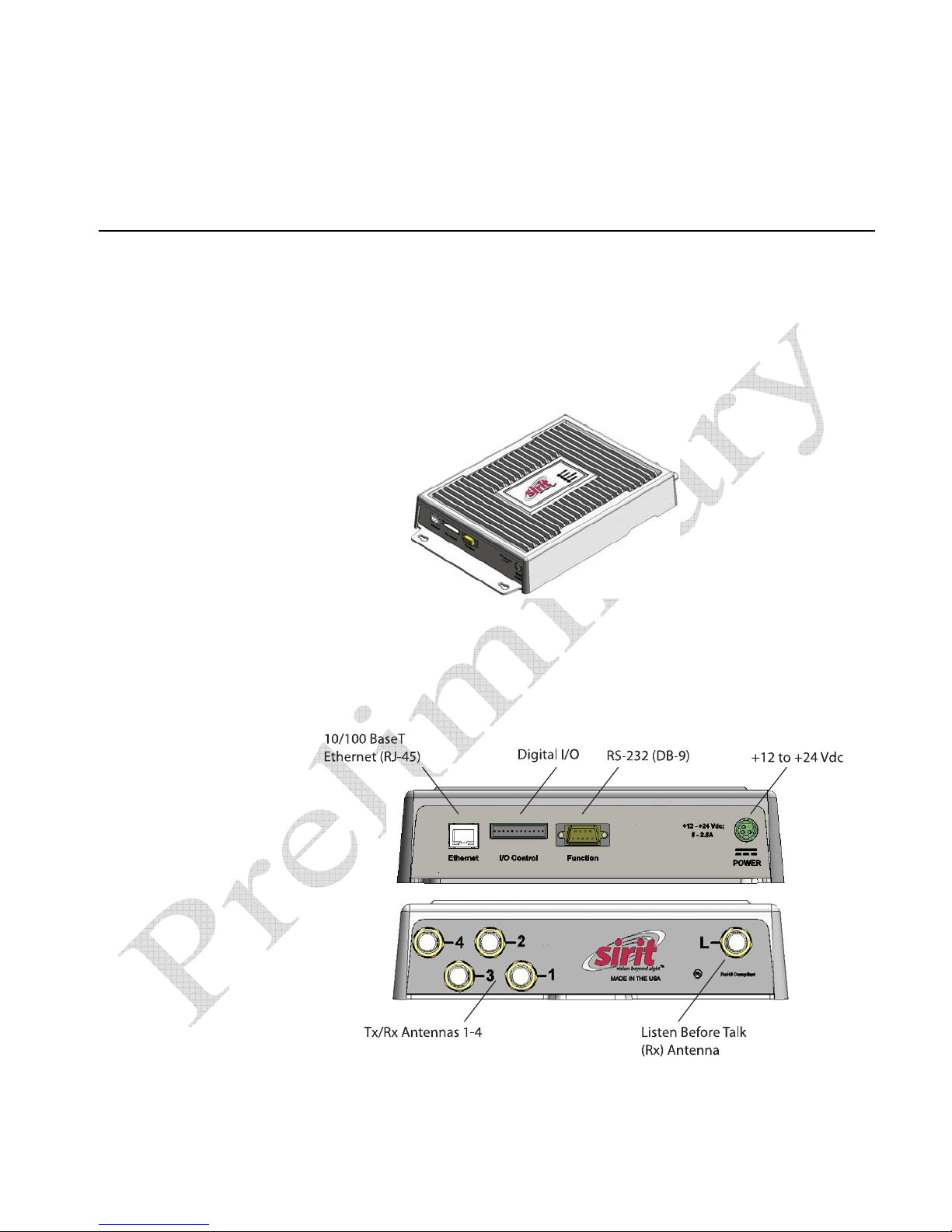
Figure 1 INfinity 510 UHF Reader
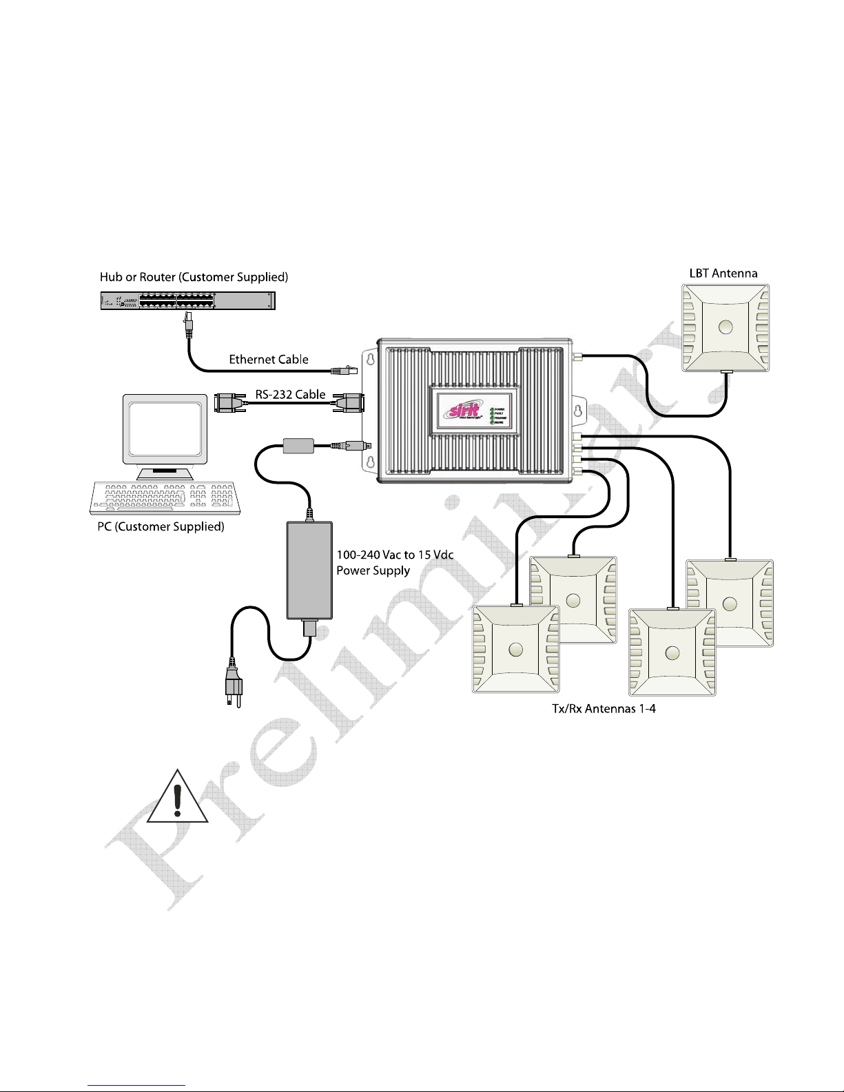
As shown in the following figure, this high performance reader supports up
to four Tx/Rx antennas and one Listen before Talk (LBT) antenna and is
equipped with both serial and Ethernet interfaces. Discrete digital inputs
and outputs are also provided.
Figure 2 INfinity 510 Power and I/O Connections
INfinity 510 User’s Guide, P1.04
1
Page 4
2 3 4 5 6
1
Reader Overview
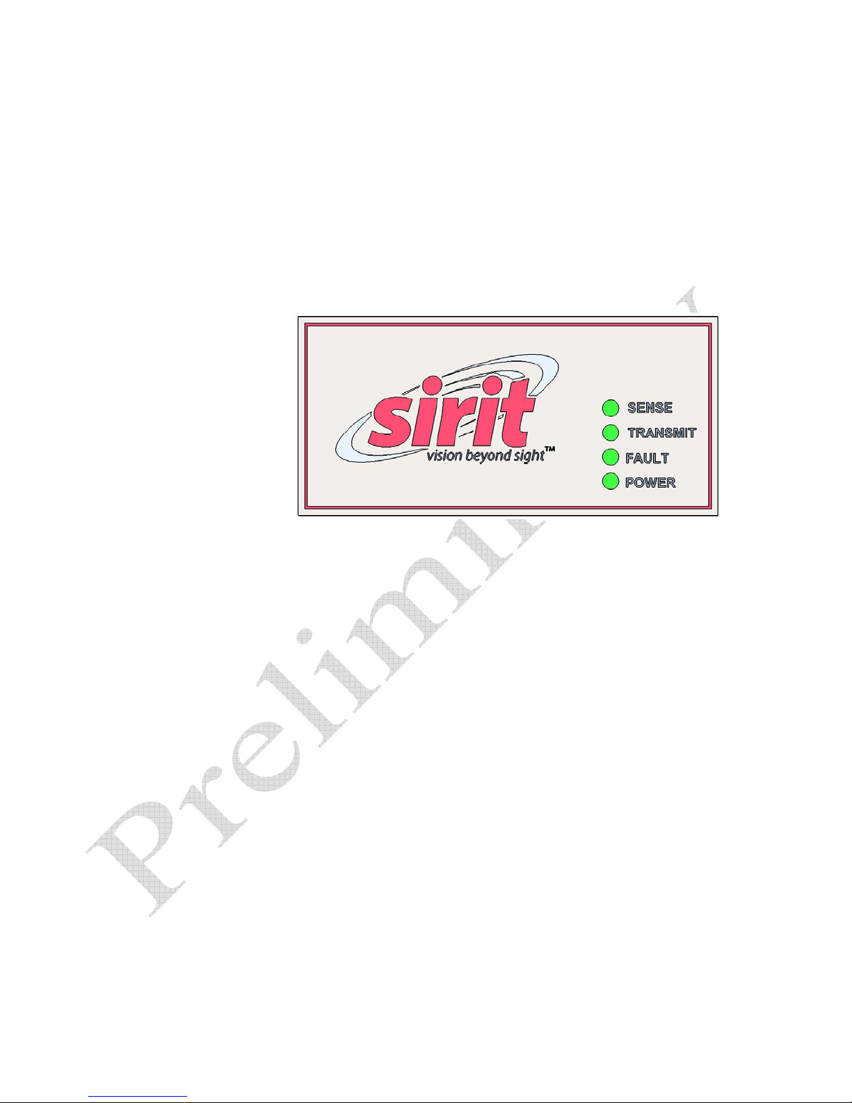
The INfinity 510 is equipped with four status indicators located on the top of
the enclosure. These LEDs provide indication for the following:
h Sense – Indicates reader has detected a tag in the RF field.
h Transmit – Indicates the reader’s transmitter is operating (RF on).
h Fault – Indicates a fault occurred.
h Power – Indicates that power is applied to the reader.
During power up, the LEDs will momentarily flash.
2
INfinity 510 User’s Guide, P1.04
Page 5
1
3 4 5 6
2
Reader Equipment Installation
Reader Equipment Installation
Mechanical Installation
Mounting the Reader
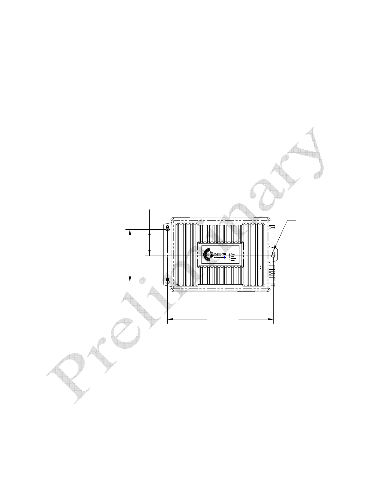
The INfinity 510 is equipped with two mounting flanges and slotted
keyholes that accept three #8 (M4) mounting screws. Predrill any mounting
surface according to the following dimensions. Any mounting surface must
be able to support up to four pounds (1.8 kg).
3 3/32"
(78.6 mm)
6 3/16"
(157.2 mm)
Concrete Wall Mounting
To mount the INfinity 510 to a hollow concrete block wall, Sirit recommends
metal sleeve type concrete anchors that accept #8 screws and flat washers.
Wood or Metal Wall Mounting
To mount the INfinity 510 to a wood or sheet metal wall, Sirit recommends
either #8 x 1 inch wood screws or #8 x 1 inch sheet metal screws and
washers.
12 15/32"
(316 mm)
(3X) LOCATION
FOR #8 Screw (M4)
INfinity 510 User’s Guide, P1.04
Drywall Mounting
To mount the INfinity 510 to drywall or sheetrock, Sirit recommends either
#8 toggle bolts or #8 drywall anchors.
3
Page 6
1
3 4 5 6
2
Reader Equipment Installation
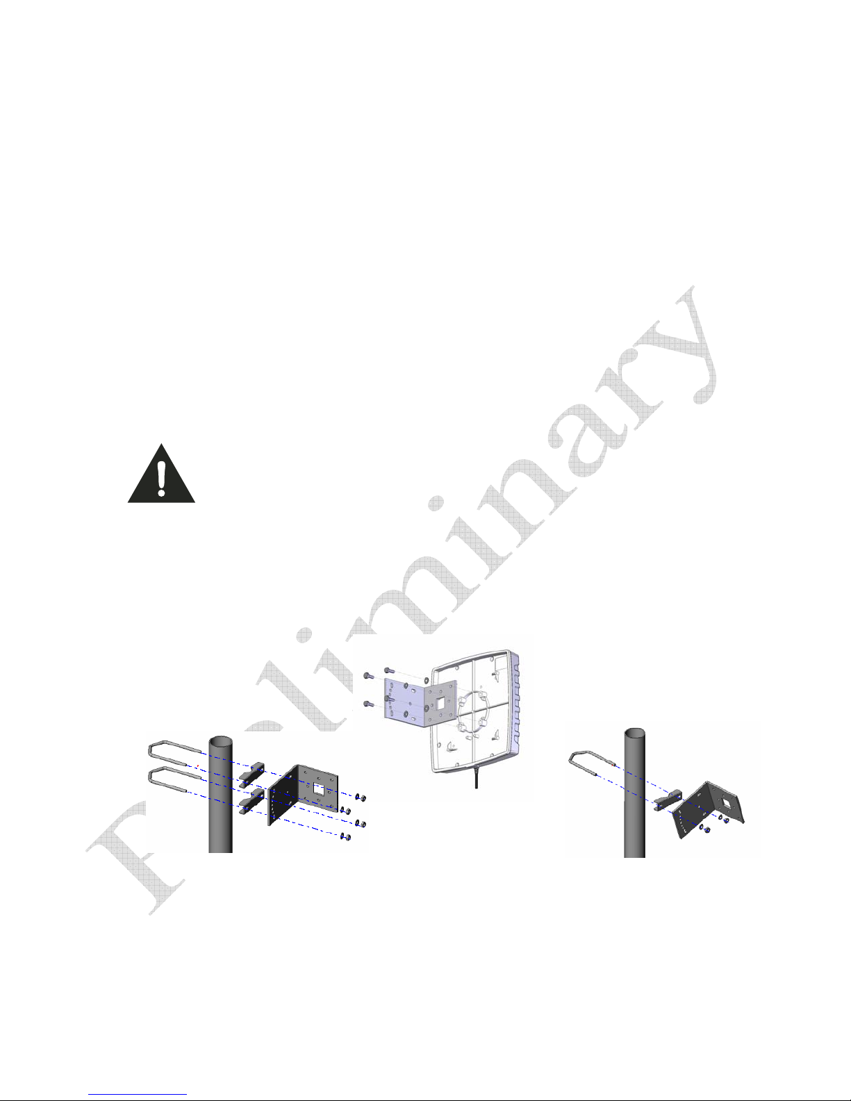
Mounting the Antennas
The INfinity 510 supports from one to four antennas in a variety of
configurations. One and two-antenna configurations are typical for most
conveyor and container tracking. Four-antenna configurations are used for
portals and loading dock doorways.
The optional Sirit provided antennas are for indoor use only and must be
installed on a solid surface or frame to prevent damage or later
misalignment. It is highly recommended that the antenna mounting be
adjustable in order to obtain the best performance from the system.
WARNING:
FCC Radiation Exposure Statement. The antennas used for this transmitter
must be installed to provide a separation distance of at least 20 cm from all
persons and must not be co-located or operating in conjunction with any other
antenna or transmitter.
.
Typical Antenna Pole Mount
4
INfinity 510 User’s Guide, P1.04
Page 7
1
3 4 5 6
2
Reader Equipment Installation
Electrical Installation
Caution:
Connecting the Serial Port
INfinity 510 User’s Guide, P1.04
The INfinity 510 is designed to meet the regulatory requirements in those
jurisdictions in which it is offered. Changes or modifications not expressly
approved by Sirit Inc for compliance could void the user's authority to operate
the equipment.
The INfinity 510 is equipped with one DB9 type RS-232 serial port for
communication up to 115 Kbaud. If you are using the serial port for reader
communication, connect a serial cable from the COM port on your PC to the
serial port on the reader. See Figure 2 for location of the connector.
5
Page 8

1
3 4 5 6
2
Reader Equipment Installation
Connecting the Ethernet Port
Ethernet Cables
In most cases, you
will connect the
INfinity 510 to a
network hub or
router. However, if
you are connecting
directly to a PC or
other computer,
you will need a
Crossover Cable
that swaps the Tx
and Rx signals.
The maximum Ethernet cable length is 30 meters. If you are communicating
with your reader across a Local Area Network (LAN), connect an Ethernet
cable from your hub or router to the RJ-45 connection. See Figure 2 for
location of the connector. If you are connecting the reader directly to a PC,
you must use a crossover cable. See Note to the left.
Connecting the Antennas
The maximum antenna cable length is 10 meters. Connect the antenna to
Caution:
antenna port
2-4. If applicable, connect the LBT antenna to the
The INfinity 510 UHF Reader is equipped with four (4) RF ports. To prevent reader
damage, active RF ports must be properly terminated with a 50 ohm load or a
functional UHF antenna before power up. UHF Readers are factory configured to
operate on RF port 1. As a result, port 1 must be properly terminated before
initially powering on the reader. Before activating any additional RF ports, they
must also be properly terminated. Never power up the reader unless the
appropriate loads or antennas are connected. Always power down the reader
before removing an antenna or load from an RF port.
The maximum antenna cable length is 10 meters.
1. If you are using additional antennas connect them to Ports
Listen port
6
Connecting Digital Inputs/Outputs
The INfinity 510 is equipped with a general purpose digital input/output
(I/O) port that provides four optically isolated 5-24 Vdc input signals and
four open-collector output signals. The digital inputs can be used as general
purpose inputs or to trigger the reader for tag reading. These inputs can be
configured to provide an external read trigger from proximity sensors,
photoswitches, or other devices.
The digital outputs can be used as general purpose outputs, to indicate tag
reading activity, or to indicate the reader is transmitting (RF On). The
outputs can also be configured to trigger conveyor gates or other access
control and sorting devices.
Connecting the Power
Connect the 15 Vdc power supply to the reader and connect the power
supply to your 100-240 Vac, 50-60 Hz power source. Allow 30 seconds for
the reader to initialize.
INfinity 510 User’s Guide, P1.04
Page 9
1 2
4 5 6
3
Reader Software Installation
Reader Software Installation
Installing Reader Configuration Software
The INfinity 510 is equipped with a Microsoft Windows PC application called
Reader Startup Tool (RST). You can use this application to configure the
reader as well as read and display tag data.
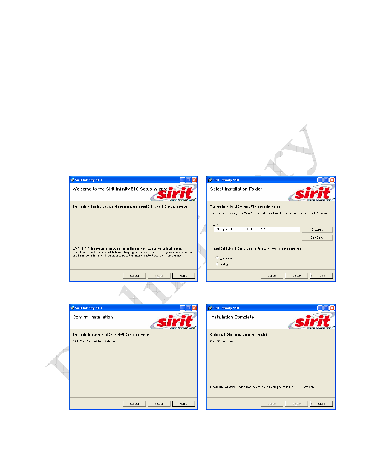
Install RST
1 To install RST, load your system CD and double-click the Setup.exe file:
2 Press Next>
4 Press Next> 5 Press Close when the installation is
INfinity 510 User’s Guide, P1.04
3 Verify the directory and path where the
RST files will be installed. Press Next>
complete.
7
Page 10
1 2 3
5 6
4
Start RST
To start your reader configuration, open the RST application.
Open RST
1 From your Windows desktop, select:
Start→Programs→Sirit→INfinity510→Reader Startup Tool
Reader Configuration
Reader Configuration
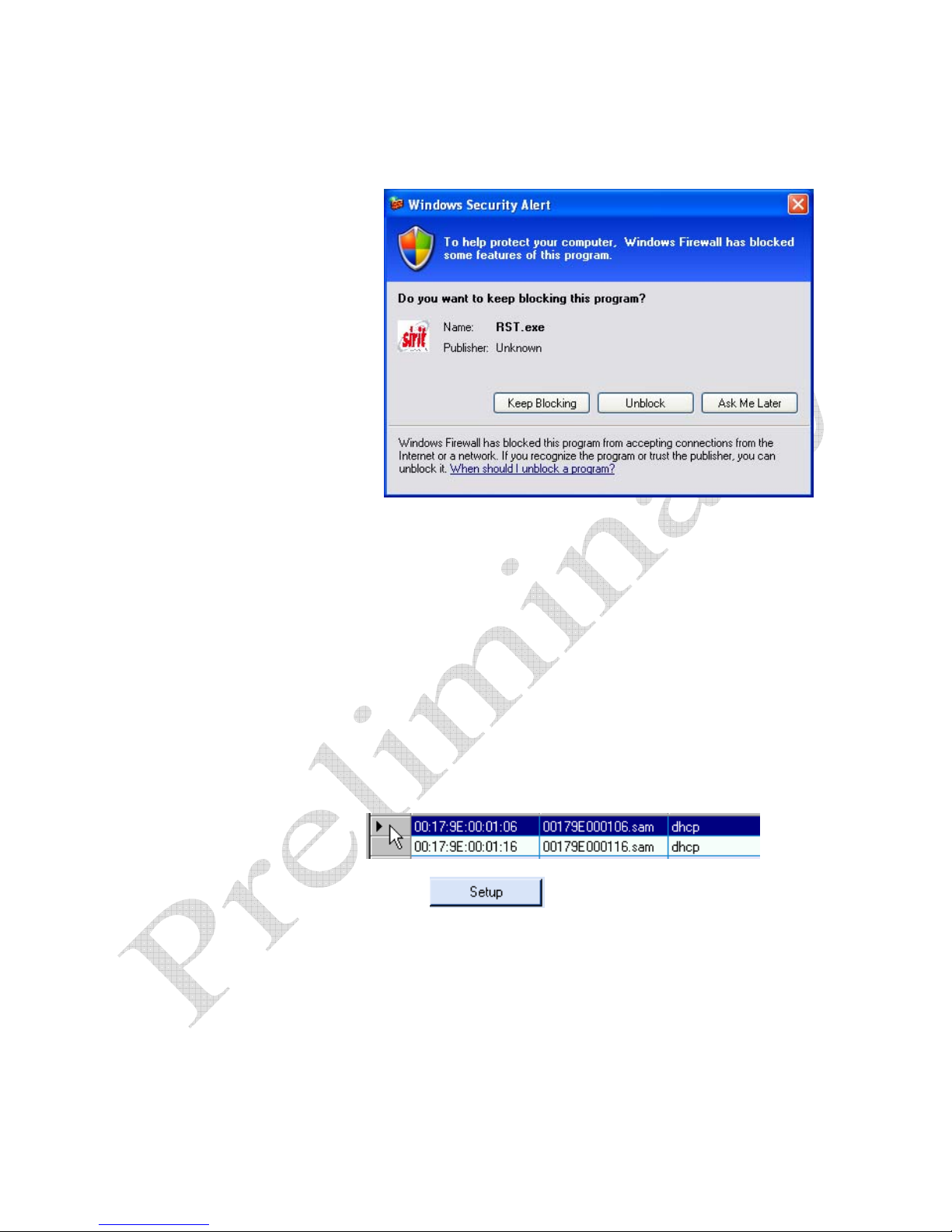
2 If this is the first time starting the RST application, you may receive a
3 If the warning window is hidden under the RST windows, collapse the
8
Windows Security Alert. This warning indicates that the firewall is
blocking the RST application.
RST window.
INfinity 510 User’s Guide, P1.04
Page 11
1 2 3
5 6
4
Reader Configuration
4 Press Unblock.
5 Press
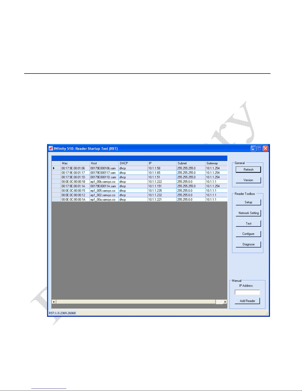
6 The RST main screen will display any readers currently connected to
Refresh on the RST
the network.
Initial Reader Setup
To configure a specific reader, perform the following:
Reader Setup
1 Select the reader on the main RST screen by clicking the button to the
left of the reader Mac address.
2 Press the
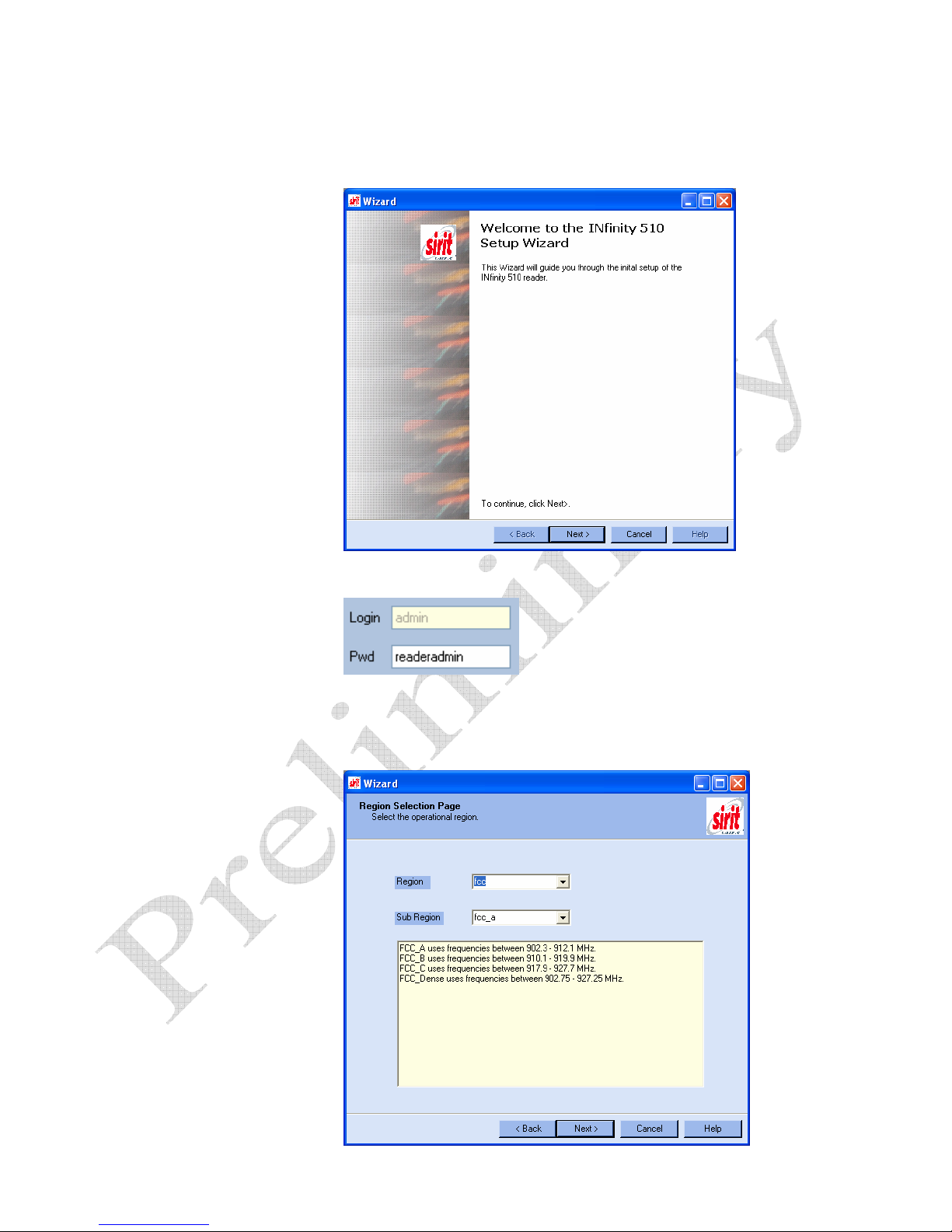
3 The INfinity 510 Setup Wizard is displayed.
button on the RST window.
INfinity 510 User’s Guide, P1.04
9
Page 12
1 2 3
5 6
4
Reader Configuration
4 Press
5 Enter the Login (admin) and Password. If this is the first time
6 Press
Next>.
configuring your reader, enter: readeradmin
Next>.
10
INfinity 510 User’s Guide, P1.04
Page 13
1 2 3
Custom Setup
If your installation
type differs from one
of the choices shown
in the Setup Wizard,
you can always
customize your setup
later using the
embedded web
interface capability.
See the Advanced
Setup chapter in this
guide for more
information.
5 6
4
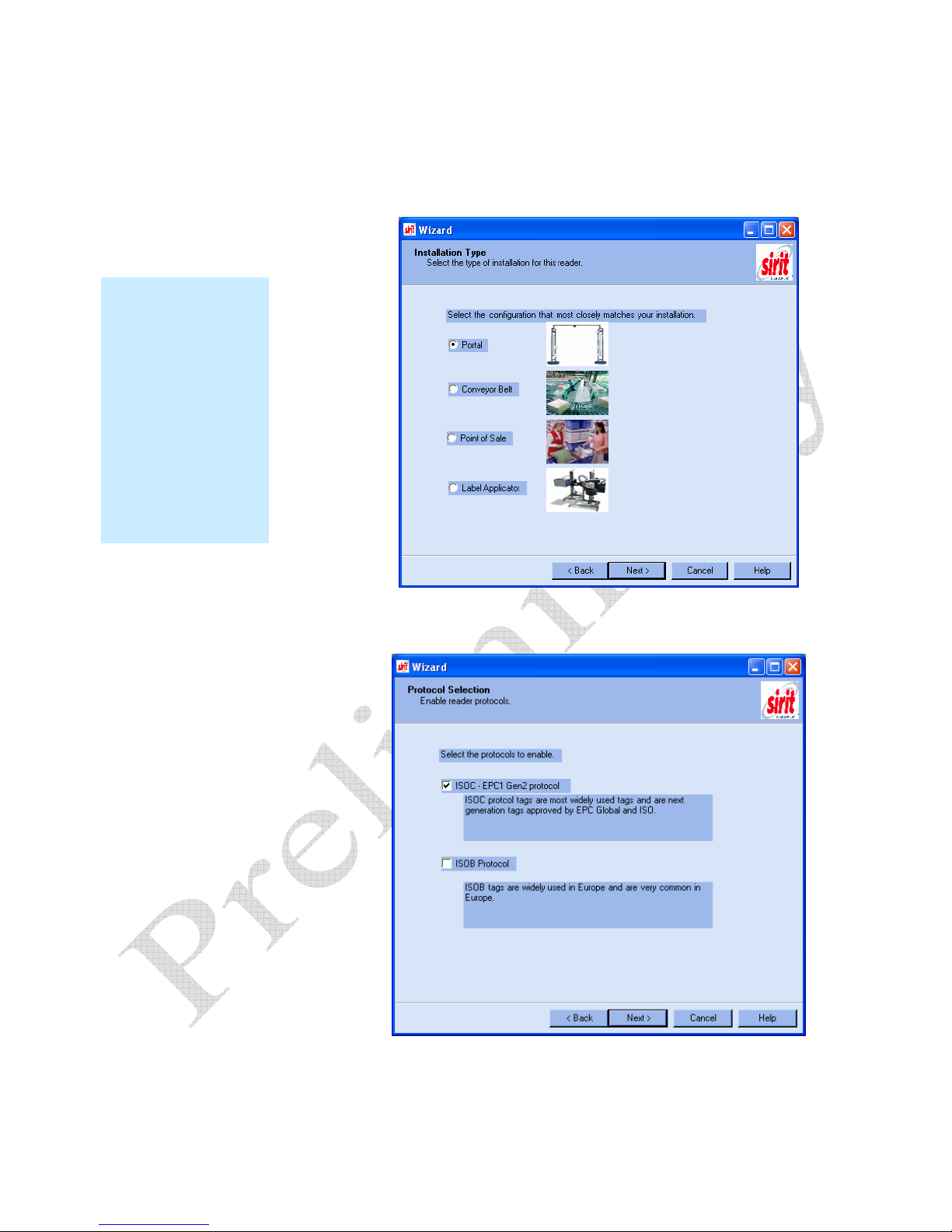
7 Select the Region and Sub Region from the pull-downs and press Next>.
Reader Configuration
8 Select a configuration that most closely resembles your installation and
press
Next>.
INfinity 510 User’s Guide, P1.04
9 Select the protocol of the tags you will be reading and press
Next>.
11
Page 14
1 2 3
5 6
4
Reader Configuration
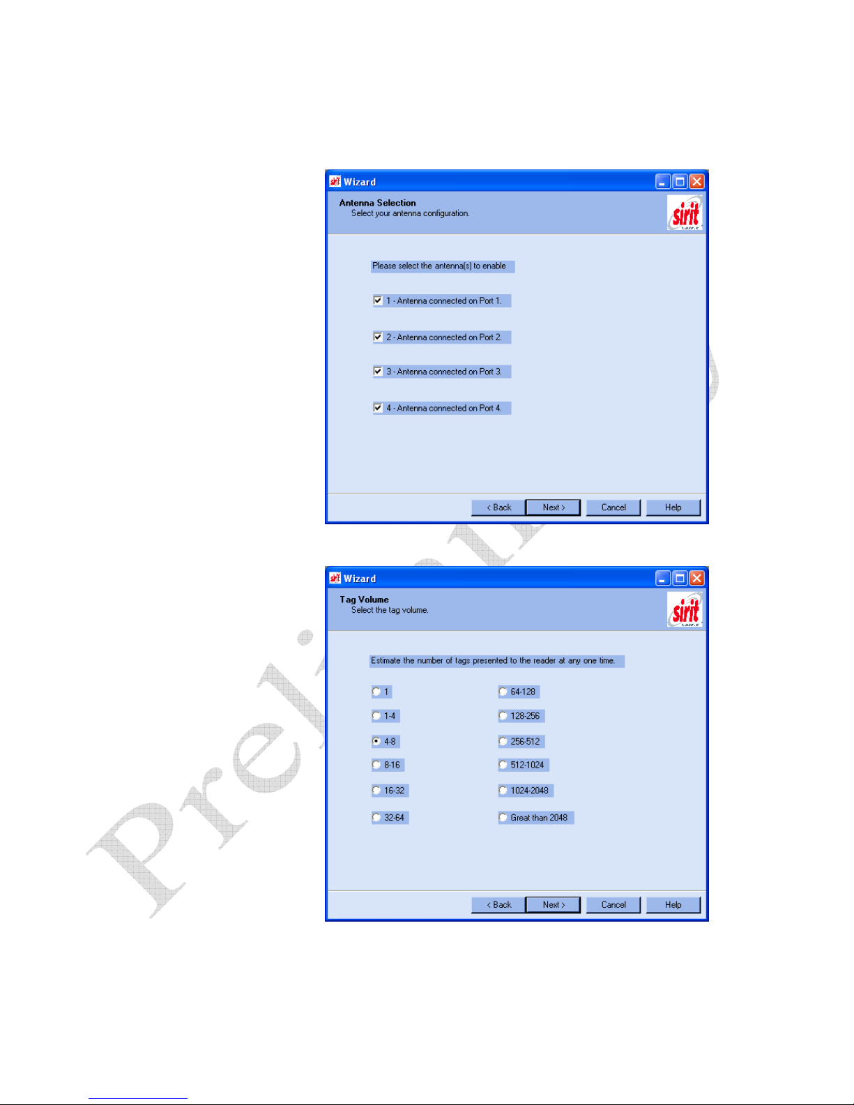
10 Select the antennas you will be installing and press
Next>.
11 Estimate the number of tags that will be presented to the reader at any
12
one time and press
Next>.
INfinity 510 User’s Guide, P1.04
Page 15
1 2 3
5 6
4
Reader Configuration
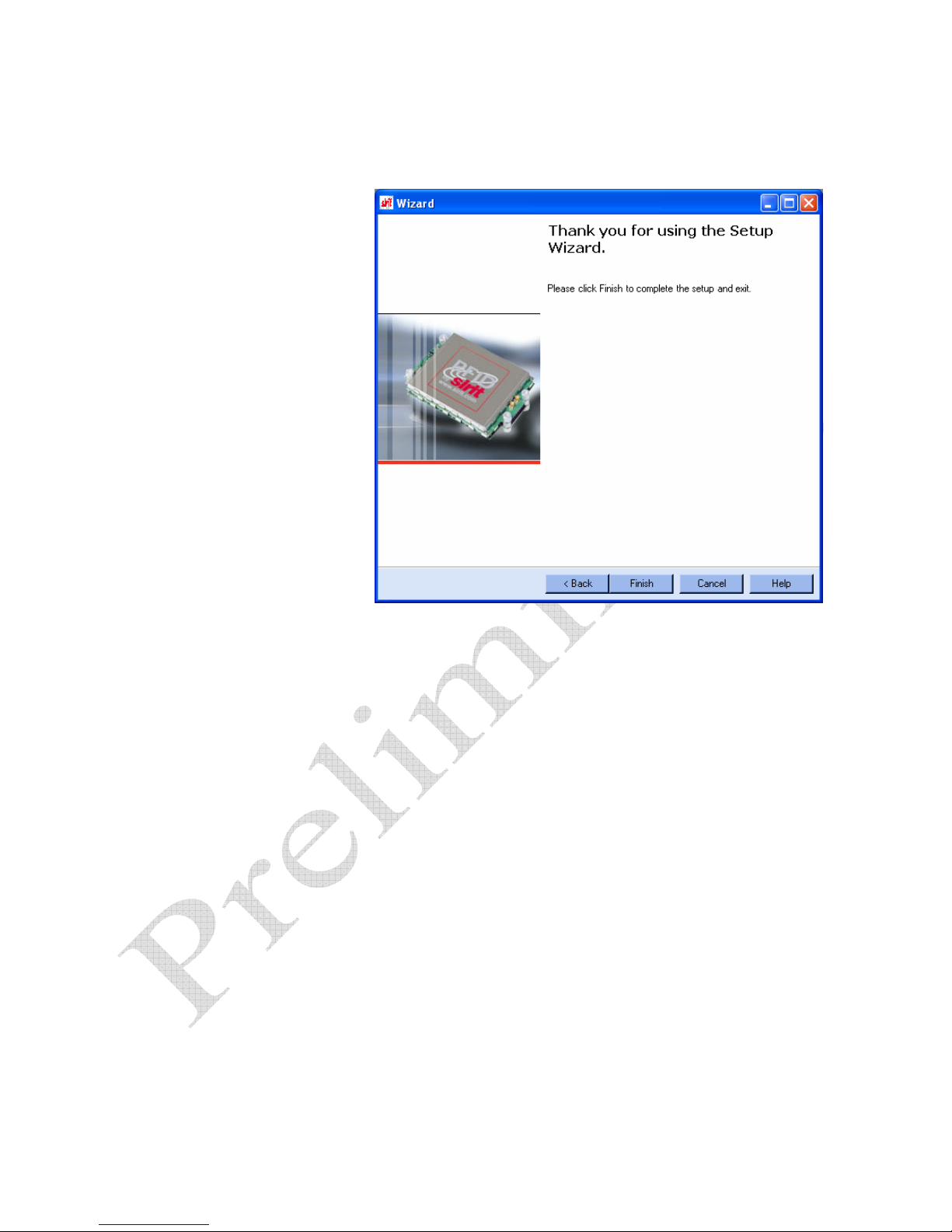
12 Press Finish to complete the initial reader setup.
INfinity 510 User’s Guide, P1.04
13
Page 16
1 2 3 4
6
5
Reader Operation
Basic Operation with the Reader Operation Tool
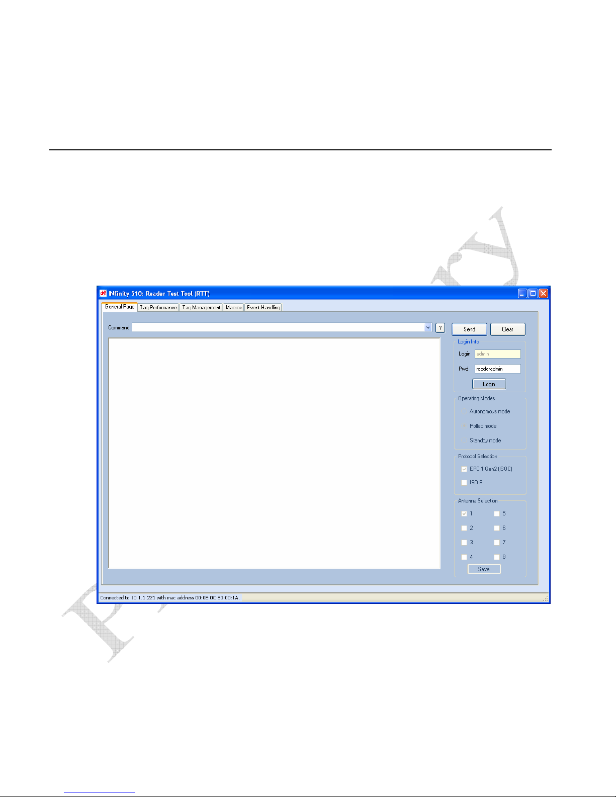
The INfinity 510 can be operated either from the RST application or by
logging directly into the reader’s embedded web interface. To operate the
reader from RST, perform the following:
1 From the RST main screen, press Operate Reader. The Reader
Operator Tool (ROT) is displayed.
Reader Operation
2 Login to the reader. The initial password (
3 Verify the Operating Mode is set to
14
Pwd) is readeradmin. See
the Advanced Setup section for details on changing the password.
Polled Mode.
INfinity 510 User’s Guide, P1.04
Page 17
1 2 3 4 5 6
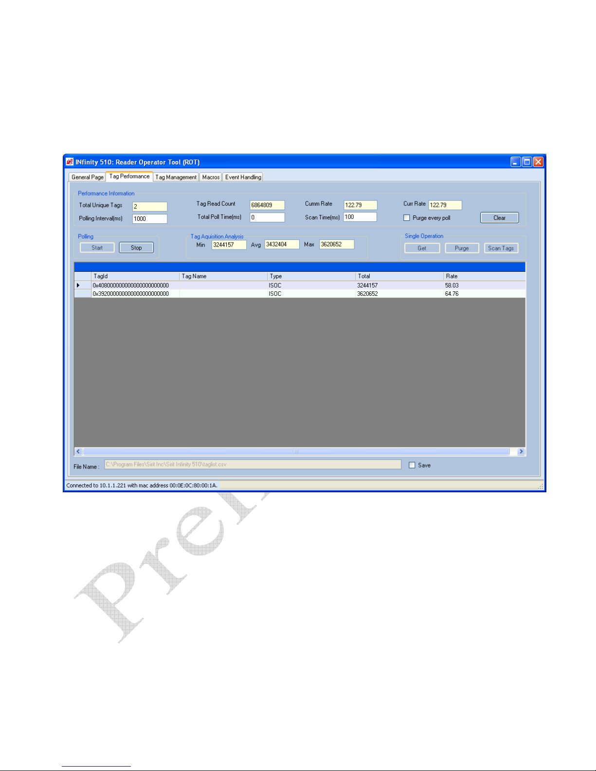
4 Select the Tag Performance tab.
Reader Operation
5 Press
Start.
INfinity 510 User’s Guide, P1.04
6 Place your tags in front of the antenna and verify the tags are read and
displayed as shown in the previous figure.
15
Page 18
1 2 3 4
6
5
Advanced Setup
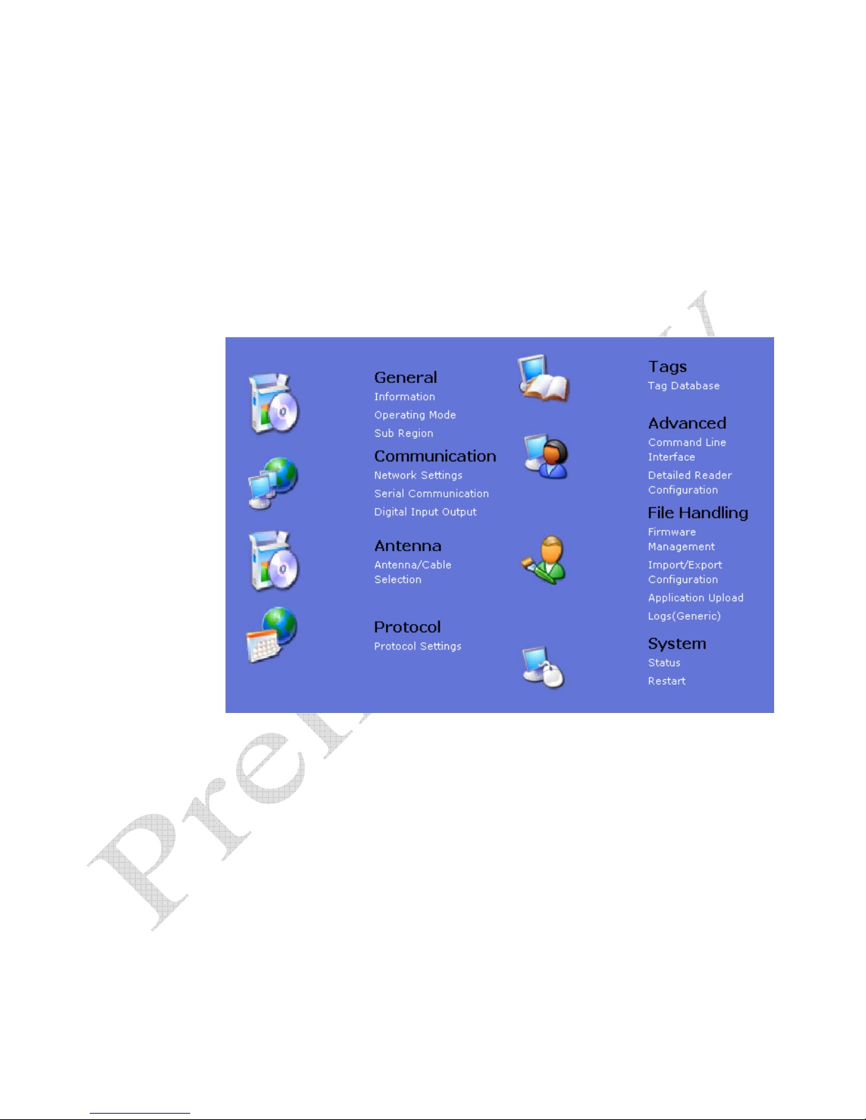
You can also customize the reader setup to more closely match your
installation. This is performed by logging directly into the reader’s
embedded web interface. You can access this interface from RST. Perform
the following:
1 From the RST main screen, press Configure. The INfinity 510 Reader
Configuration Tool (RCT) is displayed.
Reader Operation
2 Select the specific configuration category and follow the instructions.
16
INfinity 510 User’s Guide, P1.04
Page 19

1 2 3 4 5
6
Reader Specifications
Frequency 860-960 MHz
RF Power 10 mW – 2W conducted
Connections RS-232, Digital I/O, Ethernet LAN, and
WiFi 802.11 (optional)
Input Voltage 12 to 24 Vdc, 60W
Input Current 2.5A maximum at 24 Vdc
5.0A maximum at 12 Vdc
Specifications
Specifications
Environmental Specifications
Operating Temperature -4° F to 131° F (-20° C to 55° C)
Storage Temperature -40° F to 185° F (-40° C to 85° C)
Maximum Shock 1 foot (0.3 meter) drop to any corner
Relative Humidity 5% to 95% non-condensing
Case Material Aluminum
Case Dimensions 8.7 x 11.8 x 2.2 in (220 x 300 x 56 mm)
Weight 4 lbs (1.8 kg)
Battery Specifications (Optional)
Battery Lithium/Manganese Dioxide
Designation ANSI/NEDA 5012LC / IEC-CR1220
Voltage 3.0 volts
Average capacity 40 mAh to 2.0 volts
Caution - Risk of Explosion
Only replace battery with same type and designation. There is risk of explosion if
battery is replaced with incorrect type. Dispose of old battery according to
manufacturer’s instructions and local regulations.
INfinity 510 User’s Guide, P1.04
17
Page 20

1 2 3 4 5
6
Power Supply Specifications
Input Voltage 100 – 240 Vac
Input Consumption 60W maximum
Input Frequency 50 – 60 Hz
Output Voltage 15 VDC
Output Current 4A maximum
RS-232 Specifications
Connector DB-9S
Specifications
Baud rate 9600 - 115200 (Default = 57600)
Parity None
Data bits 8
Stop bits 1
Signals
Pin 1
Pin 2
Pin 3
Pin 4
Pin 5
Pin 6
Pin 7
Pin 8
Pin 9
Ethernet LAN Specifications
Connector RJ-45
Ethernet 10/100 BaseT
Indicators Yellow - Indicates link is operational
Signals
CNVSS
TXD
RXD
DTR
GND
DSR
CTS
RTSA
+3.3 Vdc
Green - Indicates network traffic detected.
Pin 1 – TXD+ (Transmit Data +)
Pin 2 – TXD- (Transmit Data -)
Pin 3 – RXD+ (Receive Data +)
Pin 4 – EPWR+ (Power from switch +)
Pin 5 – EPWR+ (Power from switch +)
Pin 6 – RXD- (Receive Data -)
Pin 7 – EPWR- (Power from switch -)
Pin 8 – EPWR- (Power from switch -)
18
INfinity 510 User’s Guide, P1.04
Page 21

1 2 3 4 5
6
Digital Input/Output Specifications
Connector Plugcon 31374112 (1x12)
Input 5 to 24 Vdc, 1 to 5 mA, Optically Isolated
Output Open Collector (3 to 40 V, 100 mA Max)
Signals
Pin 2 – DIN1 (Digital Input 1)
Pin 3 – DIN2 (Digital Input 2)
Pin 5 – DIN3 (Digital Input 3)
Pin 6 – DIN4 (Digital Input 4)
Pin 1, 4 – Digital input common
Pin 8 – DOUT1 (Digital Output 1)
Pin 9 – DOUT2 (Digital Output 2)
Pin 10 – DOUT3 (Digital Output 3)
Pin 11 – DOUT4 (Digital Output 4)
Pin 7,12 – Digital output common
Specifications
Antenna Specifications
Type PATCH
Frequency (FCC) 860 – 960 MHz
Polarization Circular
Gain 7 dBi ± 1 dBi, max
VSWR, maximum
Axial ratio
Input impedance
Power Handling
Size
Weight
Caution:
This device has been designed to operate with no more than 1 Watt into the
antenna and an antenna gain of no more than 6 dBic. Antenna having a higher
gain is strictly prohibited per regulations of Industry Canada, unless power into
the antenna is decreased to compensate for the increased antenna gain. The
required antenna impedance is 50 ohms.
To reduce potential radio interference to other users, the antenna type and its
gain should be so chosen that the equivalent isotropically radiated power (EIRP) is
not more than that required for successful communication.
The installer of this radio equipment must ensure that the antenna is located or
pointed such that it does not emit an RF field in excess of Health Canada limits for
the general population; consult Safety Code 6, obtainable from Health Canada’s
website at www.hc-sc.gc.ca/rpb
Optional Sirit supplied antennas are for indoor use only.
1.3:1 or less
1 dB or less
50 Ohm (nominal)
10 W
245 mm x 235 mm x 40 mm
470g
.
INfinity 510 User’s Guide, P1.04
19
Page 22

1 2 3 4 5
6
Power Disconnect Device
The plug on the power supply cord is intended to be the power disconnect
device. As a result, the power source (socket or outlet) shall be located near
the equipment and shall be easily accessible.
Safety Instructions
Safety Instructions
WARNING:
Caution:
Caution: Risk of Explosion. Only replace battery with same type and designation.
FCC Radiation Exposure Statement. The antennas used for this transmitter
must be installed to provide a separation distance of at least 20 cm from all
persons and must not be co-located or operating in conjunction with any other
antenna or transmitter.
.
The INfinity 510 UHF Reader is equipped with four (4) RF ports. To prevent
reader damage, active RF ports must be properly terminated with a 50 ohm
load or a functional UHF antenna before power up. UHF Readers are factory
configured to operate on RF port 1. As a result, port 1 must be properly
terminated before initially powering on the reader. Before activating any
additional RF ports, they must also be properly terminated. Never power up
the reader unless the appropriate loads or antennas are connected. Always
power down the reader before removing an antenna or load from an RF port.
The maximum antenna cable length is 10 meters.
There is risk of explosion if battery is replaced with incorrect type. Dispose of
old battery according to manufacturer’s instructions and local regulations.
20
INfinity 510 User’s Guide, P1.04
 Loading...