

Sirio Antenne SKA 900 1/4, SKA 901 1/4 Installation Manual
SKA 900 1SKA 900 1
SKA 900 1SKA 900 1
SKA 900 1/
4 SKA 901 14 SKA 901 1
4 SKA 901 14 SKA 901 1
4 SKA 901 1/
44
44
4
UHF Mobile Antennas 824-960 MHzUHF Mobile Antennas 824-960 MHz
UHF Mobile Antennas 824-960 MHzUHF Mobile Antennas 824-960 MHz
UHF Mobile Antennas 824-960 MHz
Installation ManualInstallation Manual
Installation ManualInstallation Manual
Installation Manual
B Copyright SIRIO antenne - Technical Data are subjected to change - Printed in ITALY - Rev. 14/05/2004- Cod. ID276
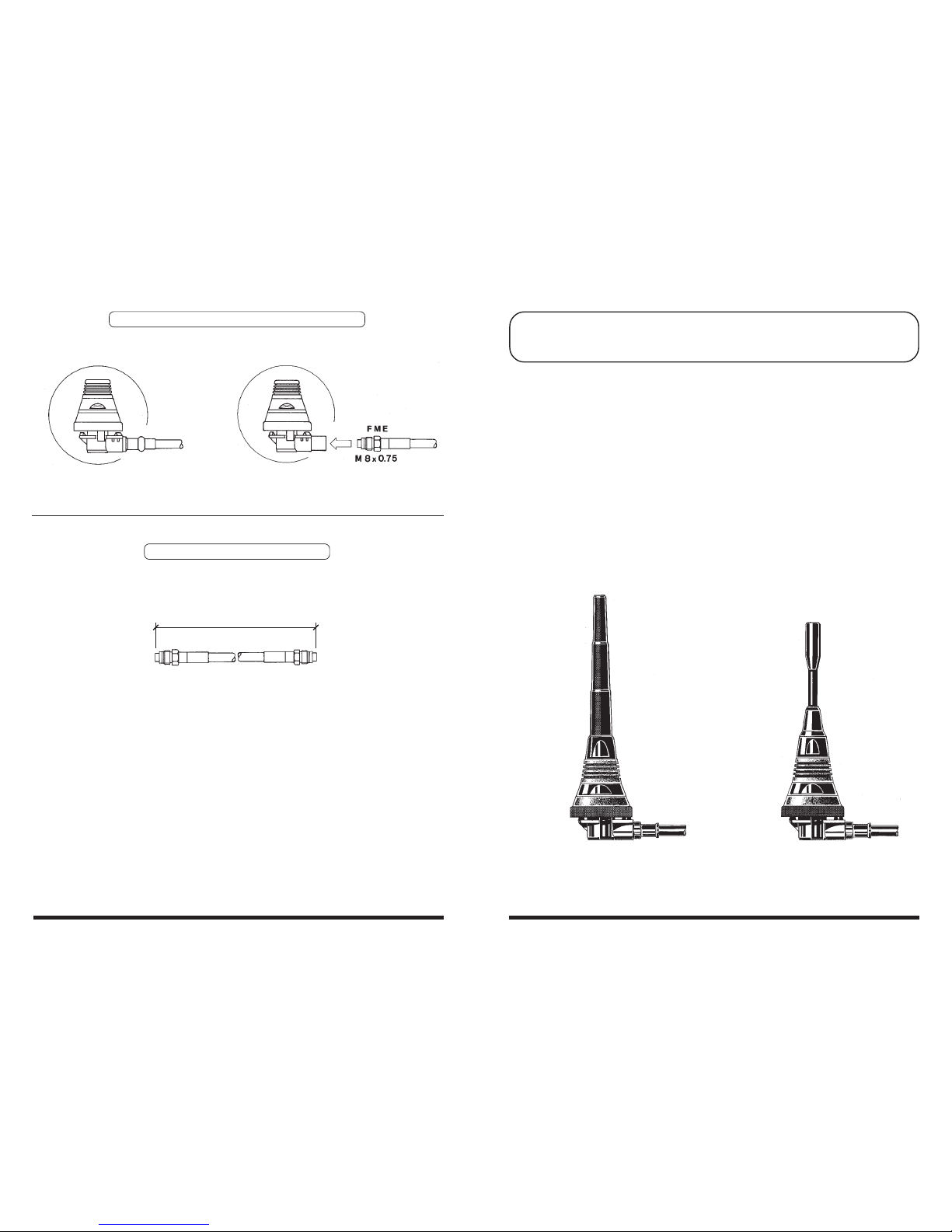
"ML" base with 5m cable "ML" base with FME connection
OPTIONAL SPARE CABLES
(only "ML" with FME connection)
Length
P/N 2510305.00 0.5 m RG 58 C/U cable + 2 FME
P/N 2510405.00 1.5 m RG 58 C/U cable + 2 FME
P/N 2510505.00 3.5 m RG 58 C/U cable + 2 FME
P/N 2510605.00 5.0 m RG 58 C/U cable + 2 FME
SKA 900 1/4 SKA 901 1/4
ALTERNATIVE CABLE CONNECTION
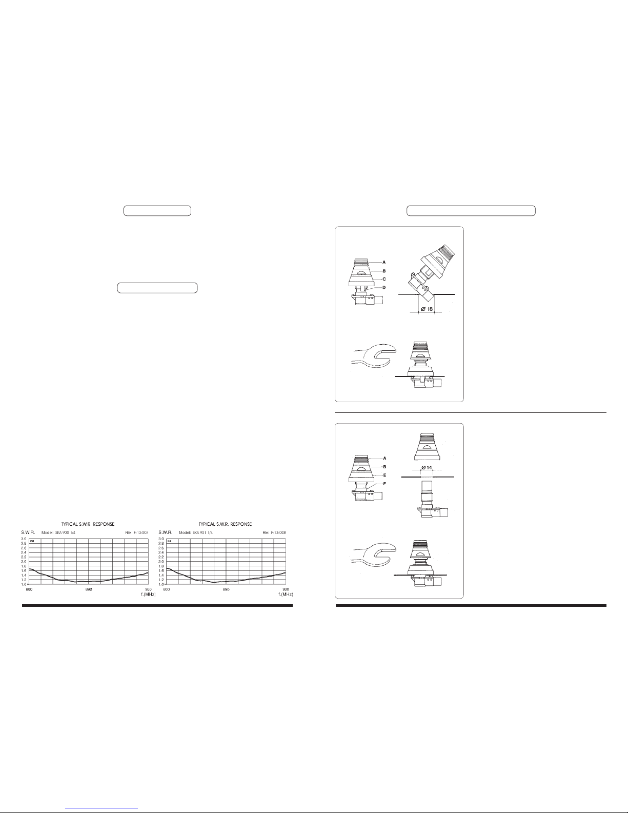
MOUNTING INSTRUCTIONS
SPECIFICATIONS
DESCRIPTION
1/4 λ vehicular antennas specially conceived for CELLULAR systems working on 900 MHz. The
whip and all the metallic components are made of brass completely black chromed. They are
supplied with "ML" (Micro Line) mount of reduced dimensions for a handy installation on the
vehicle and 5m cable RG 58 C/U with FME connector. Both models are also available without
cable and with FME connector directly assembled on the base.
Electrical Data
Type :
Frequency Range :
Impedance :
Radiation :
Polarization :
Gain :
V.S.W.R. in bandwidth :
Max Power :
Feed System / Position :
Standard Mount :
Cable Lenght / Type :
Mechanical Data
Materials :
Heigth (approx.)
SKA 900 1/4 :
SKA 901 1/4 :
Weight (approx.) :
Mounting Hole :
1/4 λ
824-960 MHz (for AMPS, TACS and GSM systems)
50 Ω Unbalanced
Omnidirectional
Vertical
0 dB ref. to a λ/4 whip
≤ 1.8 : 1
30 Watts (CW) at 50° C
Direct / Base
"ML"
5 m / RG 58
Chromed Brass, Zinc, Nylon, Rubber
89 mm
85 mm
250 gr
∅ 14 or 18 mm
Mounting from the outside
1.1 Drill a 18 mm hole, deburr it and
protect it against corrosion. Loose part B,
push it upwards together with part C and
hold it tightly.
1.2 Insert the base into the mounting
hole and decentralize it. Insert the plastic
fish-plates D of part C into the hole. Screw
on part B with a 20 mm open-end
wrench.
The ring nut B is tightened correctly,
if the upper edge of part A is at the
same height as the inner thread-bolt
Mounting from the inside
2.1 Drill a 14 mm hole, deburr it and
protect against corrosion. Loose part B
and use the item E.
Insert from below part F into the hole up
to the stop.
2.2 Push part A,B and E from above and
screw them on with a 20 mm open-end
wrench.
Part B is tightened correctly, if the
upper edge of part A is at the same
height as the inner thread-bolt.
1.1
1.2
2.1
2.2
ID276
 Loading...