

Sirio Antenne GPF 21 N Installation Manual
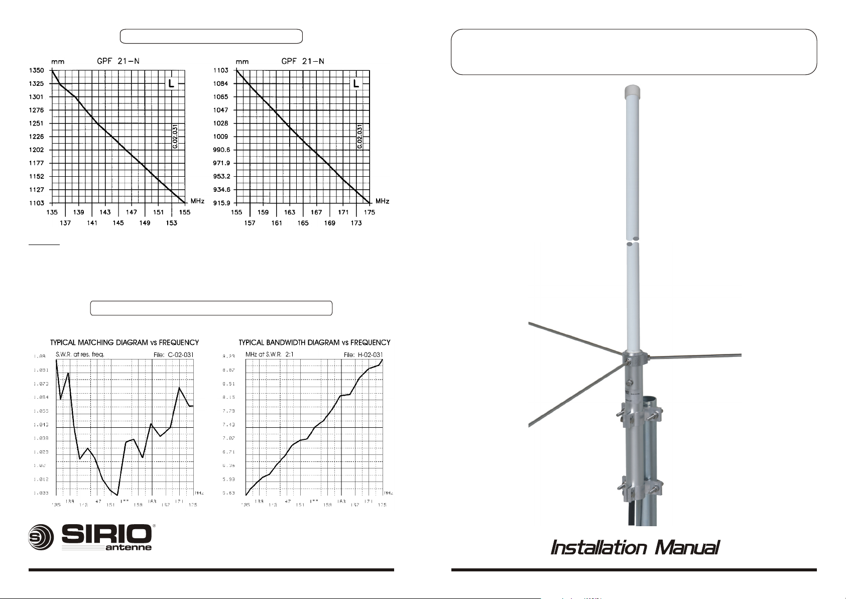
TYPICAL TUNING DIAGRAMS
NOTE:
! Use the curves just as a guide. For fine-tuning please use an SWR-Meter.
MATCHING & BANDWIDTH DIAGRAMSMATCHING & BANDWIDTH DIAGRAMS
GPF 21 N
GPF 21 N
VHF Base Station Antenna 135...175 MHz
HI-QUALITY ANTENNAS MADE IN ITALY
B Copyright SIRIO antenne - Technical Data are subjected to change - Printed in ITALY - Rev. 22/12/2006 - Cod. ID270

DESCRIPTIONDESCRIPTION
5/8 l Ground Plane base station colinear antenna for land and marine service. It works on
135...175 MHz by using the cutting diagram enclosed. The matching coil is DC feeded for a
perfect protection from the static discharges. GPF 21-N is made of fiberglass, non-corrosive
aluminium, stainless steel and its die-cast strong base assures the maximum robustness and the
best performance. Tuning is easy by following the attached directions
SPECIFICATIONSSPECIFICATIONS
Electrical Data
Type : 5/8 l Ground Plane
Frequency Range : 135...175 MHz tunable by cutting
Impedance : 50 W
Radiation (H-plane) : 360° Omnidirectional
Radiation (E-plane) : Beamwidth at -3 dB = 80°
Radiation angle deg. : 28°
Polarization : Linear Vertical
Gain : 1.5 dBd - 3.65 dBi
Bandwidth @ SWR £ 2 : see diagram
SWR @ res. freq. : see diagram
Max Power : 200 Watts
Grounding Protection :
Connector : "N"-Female, Gold Plated central pin
Mechanical Data
Materials :Fiberglass, Aluminium, Brass
Wind Load / Resistance : 55 N at 150 Km/h / 200 Km/h
Wind Surface : 0.05 m
Height (approx.) : 1730 mm
Weight (approx.) : 1200 gr
Radial Length (approx) : 495 mm
Mounting Mast : Æ 35-54 mm
All metal parts are DC-grounded, inner conductor shows a DC short
2
MOUNTING AND TUNING INSTRUCTIONSMOUNTING AND TUNING INSTRUCTIONS
44
11
33
22
1) Unlock the hexagonal socket
bottom screw using the enclosed
key.
2) Remove the internal coil.
3) Remove the top cap and push
the internal whip to the top
4) Pull the internal whip and re_
move it.
5) Choose the working frequency
and cut the whip according to the
suitable “Typical tuning diagram”.
NOTE: Use the curves just as a
guide. For fine-tuning please use
an SWR-Meter.
6) Insert the whip from the bottom
7) Mount and lock the coil, assem_
ble the top cap.
8) Lock the bottom screw.
9) Finally assemble the radials and
the side mounting bracket.
Bottom view
N-female connector
ATTENTION!!
Cut the whips on
the bottom sides only
55
88
ID270
HI-QUALITY ANTENNAS MADE IN ITALY
66
9977
 Loading...