

Sirio Antenne 2108801.00 User Manual
SD-FM DIPOLE 87-194 MHzSD-FM DIPOLE 87-194 MHz
SD-FM DIPOLE 87-194 MHzSD-FM DIPOLE 87-194 MHz
SD-FM DIPOLE 87-194 MHz
VHF Base Station Antenna 87...194 MHzVHF Base Station Antenna 87...194 MHz
VHF Base Station Antenna 87...194 MHzVHF Base Station Antenna 87...194 MHz
VHF Base Station Antenna 87...194 MHz
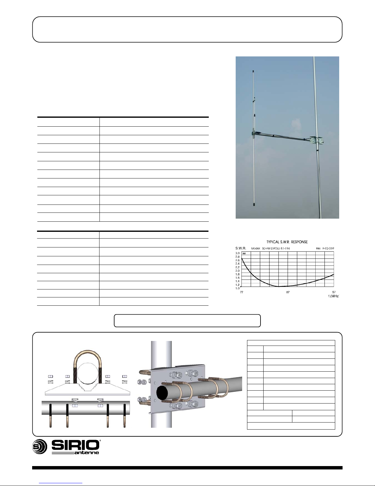
TECHNICAL DATA
Electrical Data
Type Dipole
Frequency range 87 - 194 MHz tunable by cutting
Impedance 50 Ω
Radiation (H-plane) beamwidth @ -3 dB=240° (vertical polariz. only)
Radiation (E-plane) beamwidth @ -3 dB = 80° (vertical polariz. only)
Front to back ratio ≥ 4 dB (vertical polarization only)
Polarization Linear Vertical or Horizontal
Gain 1.85 dBd - 4 dBi (vertical polarization only)
Bandwidth @ SWR 1.5 ≥ 14.5 @ 87 MHz (vertical polarization only)
SWR @ freq. res. ≤ 1.2 @ 87 MHz (vertical polarization only)
Max Power (CW) @ 30°C 300 Watts
Connector UHF-female
Mechanical Data
Materials Aluminum, Zamak, Zinc plated,Chromed Brass
Wind load / resistance 99 N @ 150 Km/h / 160Km/h
Wind surface 0.08 m
2
Boom/elements diameter 33mm/16mm
Dimensions (approx.) 1030 x 1600 mm
Weigth (approx.) 1850 gr
Turning radius (approx.) 990 mm
Operating temperature -40° C to +80° C
Mounting Mast ∅ 35-52 mm
DESCRIPTION
Dipole base station antenna working on 87-194 MHz by cutting.
Optimized for vertical polarization it can be also placed in horizontal
polarization. The elements are fixed to the boom by a strong die-cast
metal support to get the maximum strength. All connections are
waterproof and it is supplied with UHF female connector. To inprove
the antenna gain please install it in stacked or bayed array.
MOUNTING INSTRUCTIONS
SD bracket parts list
Q.ty Description
1 SD/SY Steel bracket
2 M8x200 U-bolt
4 M8 Hexagonal nut
4 M8 Grower washer
4 M8 Flat Washer
4 M6x125 U-bolt
8 M6 Hexagonal nut
8 M6 Grower washer
8 M6 Flat washer
Materials Zinc Plated Steel
Weight 865g
Re-order code: SA088
HI-QUALITY ANTENNAS MADE IN ITALY
B Copyright SIRIO antenne - Technical data are subjected to change - Printed in Italy - Rev. 21/11/2011 - Cod. ID285
Mounting Bracket
HI-QUALITY ANTENNAS MADE IN ITALY
ID285
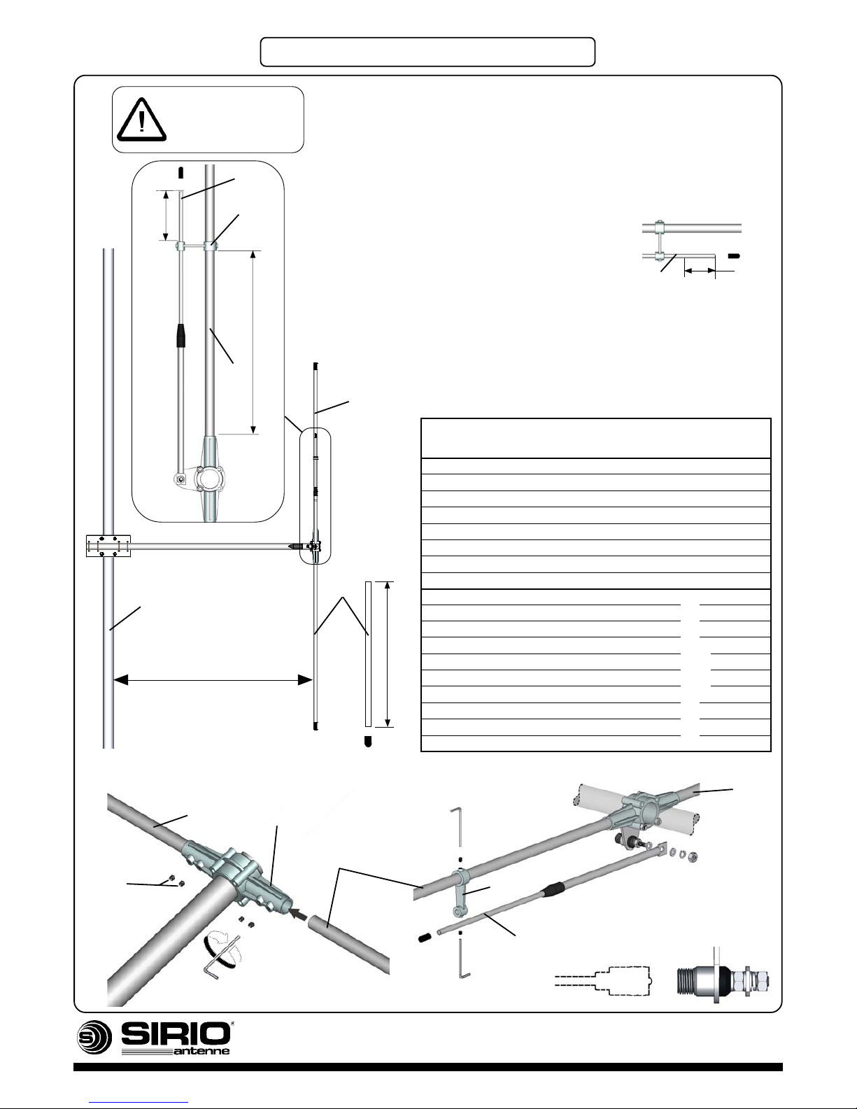
MOUNTING INSTRUCTIONS
3mm Hex. key
Hex.
socket set
screws
Element Mounting
L2
L3
A
B
C
A
ATTENTION!
Place the Gamma
Match on upper side for
vertical polarization
L4
Direction for tuning
1) Choose your working frequency.
2) Cut both tubes A at L1 (PVC cap must not be mounted).
3) Assemble both tubes A and place element B at L2.
4) Place element C of the gamma match at L3.
- working frequency 87...123 MHz: proceed at point 5).
- working frequency 123...194 MHz: cut element C
85mm from the side of PVC cap
5) You can proceed by mounting your antenna on the mast in
vertical or horizontal position.
- Vertical polarization: place your antenna at distance L4
from the mast to get the best performance
- Horizontal polarization: distance L4 is not required
Note: It is recommended to use the above table just as a guide. For fine-tuning please use an SWR-Meter.
85mm
C
L1
Freq. L1 L2 L3 L4
(MHz) (mm) (mm) (mm) (mm)
87 770 249 19 860
93 726 242 30 810
98 690 233 42 771
103 664 226 51 742
108 634 220 58 716
113 615 214 65 689
118 582 210 73 650
123 550 205 81 610
123 550 179 102 610
130 510 171 113 576
138 470 163 125 541
146 438 156 135 508
154 413 146 146 483
162 390 136 157 460
170 370 127 168 440
178 350 119 177 420
186 333 111 186 403
194 315 102 196 385
A
Element
support
Cable connection
Gamma Match
Mounting
A
A
B
C
See “Direction for tuning”
point 4
A
Mast
 Loading...