

Page 1
SAFETY INFORMATION SHEET
WARNING
INSTALLATION OF THIS PRODUCT NEAR POWER
LINES IS DANGEROUS. FOR YOUR SAFETY, FOLLOW
THE ENCLOSED INSTALLATION DIRECTIONS.
HOW TO INSTALL YOUR OUTDOOR ANTENNA
S AF ELY I N AC CO RD AN CE W I TH T HE
RECOMMENDATIONS OF THE U.S. CONSUMER
PRODUCT SAFETY COMMISSION
These safety recommendations apply to all SIRIO
commercial, amateur and general purpose communication
antennas.
dangerous installation practices are used. There are
available, trained and experienced personnel to assist in
installation, maintenance, or disassembly. Contact your
local installer if consultation or assistance is required.
YOU, YOUR ANTENNA, AND SAFETY
Each year hundreds of people are killed, mutilated or receive severe
permanent injuries when attempting to install an antenna. In many of
these cases, the victim was aware of the danger of electrocution, but did
not take adequate steps to avoid the hazard.
For your safety, and to help you achieve a good installation, please
READ and FOLLOW the safety precautions below. THEY MAY SAVE
YOUR LIFE!
SIRIO antenne assumes no liability if faulty or
SITE SELECTION
Before attempting to install your antenna, think where you can best place
your antenna for safety and performance.
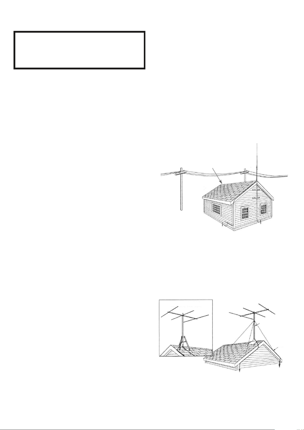
To determine a safe distance from wires, power lines and trees:
1. Measure the height of your antenna.
2. Add this length to the length of your tower or mast, and then
3. Double this total for the minimum recommended safe distance.
If you are unable to maintain this safe distance, STOP! GET
PROFESSIONAL HELP. Many antennas are supported by pipe masts
attached to the chimney, roof or side of the house. Generally, the higher
the antenna is above the ground, the better it performs. Good practice is
to install your antenna about 5 to 10 feet above the roof line and away
from power lines and obstructions. Remember that FCC limits your
antenna height to 60 feet. If possible, find a mounting place directly
above your set, where the antenna wire can take a short, vertical drop on
the outside of the house for entry through a wall or window near the set.
Your dealer carries a complete line of installation hardware.
AVOID THIS LOCATION
1.If you are installing an antenna for the first time, please, for your own
safety as well as others, seek PROFESSIONAL ASSISTANCE.
Consult your dealer. He can explain which mounting method to use for
the size and type antenna you are about to install.
2.Select your Installation site with safety, as well as performance, in
mind. (Detailed information on Site Selection appears in a separate
section of this booklet.) REMEMBER: ELECTRIC POWER LINES
AND PHONE LINES LOOK ALIKE. FOR YOUR SAFETY, ASSUME
THAT ANY OVERHEAD LINES CAN KILL YOU.
3.Call your electric power company. Tell them your plans and ask them
to come look at your proposed installation. This is a small
inconvenience considering YOUR LIFE IS AT STAKE.
4.Plan your installation procedure carefully and completely before you
begin. Successful raising of a mast or tower is largely a matter of
coordination. Each person should be assigned to a specific task, and
should know what to do and when to do it. One person should be
designated as the "boss" of the operation to call out instructions and
watch for signs of trouble.
5.When installing your antenna, REMEMBER:
DO NOT use a metal ladder. DO NOT work on a wet or windy day.
DO dress properly -shoes with rubber soles and heels, rubber gloves,
long sleeve shirt or jacket.
6.lf the assembly starts to drop, get away from it and let it fall.
Remember, the antenna, mast, cable and metal guy wires are all
excellent conductors of electrical current. Even the slightest touch of
any of these parts to a power line complete an electrical path through
the antenna and the installer-THAT'S YOU!
7.If any part of the antenna system should come in contact with a power
line-DON'T TOUCH IT OR TRY TO REMOVE IT YOUR SELF. CALL
YOUR LOCAL POWER COMPANY. They will remove it safely.
If an accident should occur with the power lines call for qualified
emergency help immediately.
The safe distance from
power lines should be
at least twice the height
of the antenna and
mast combined.
CHOOSE A PROPER SUPPORT AND MOUNTING
METHOD
However you decide to mount and support your antenna always make
sure that safety is your first concern. Some of the more common
installation methods are illustrated below.
ROOF MOUNTED
TRIPOD MOUNT
COAXIAL CABLE
GROUND WIRE
ROOF MOUNTING
The swivel feature of "universal" type mounting brackets makes a
convenient antenna mount for flat or peaked roofs. One clamp type bracket
is used with 3 or 4 guy wires equally spaced around the mast and anchored
to the roof or eaves by eyebolts. Apply roofing compound around the base of
the bracket, screws and eyebolts for moisture sealing.
SAFETY INFORMATION SHEET ID416 1/4 Rev.A
Page 2
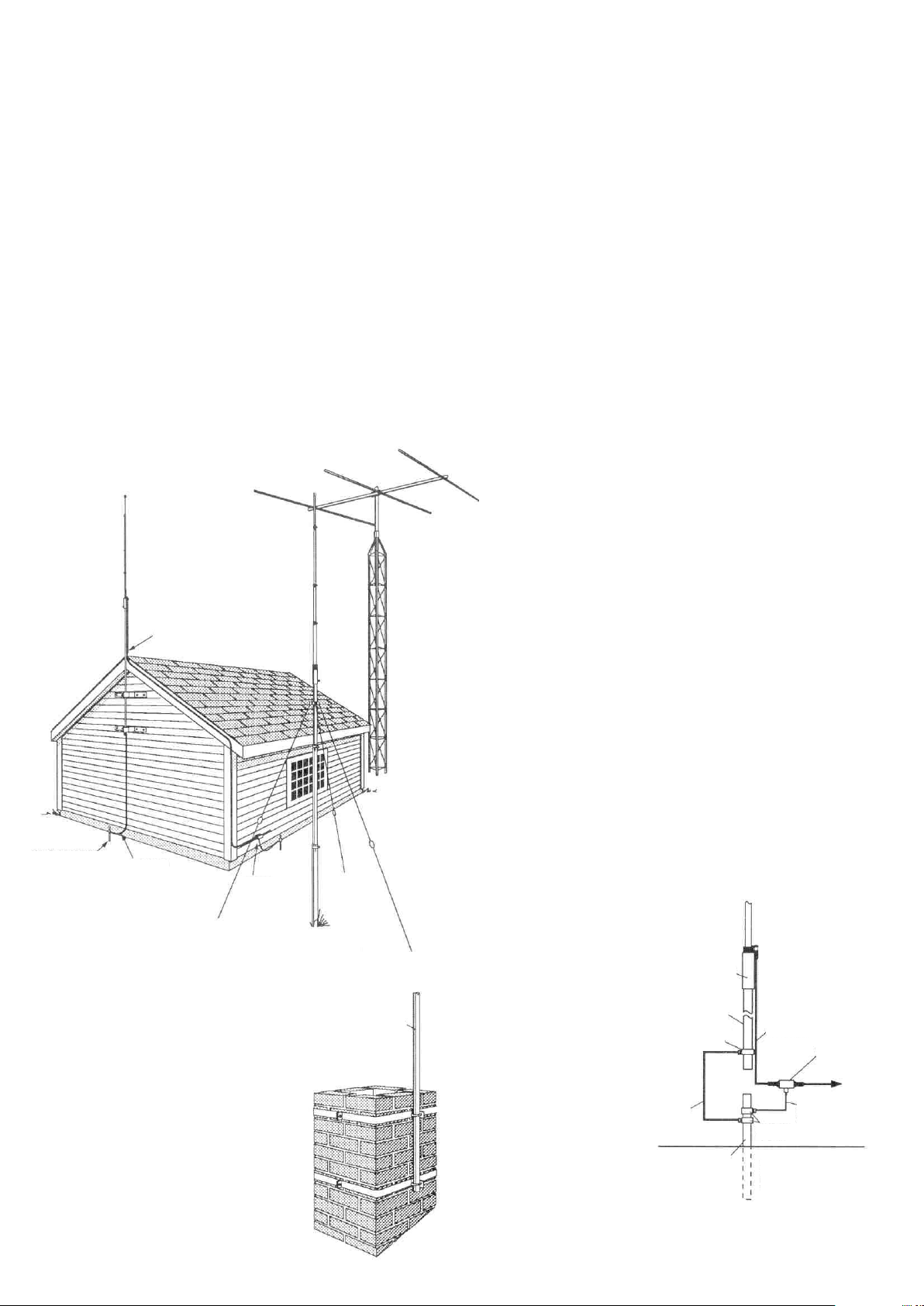
TELESCOPING MAST
Guy wires should be equally spaced in at least three directions. Use at least three
guy wires for each 10 foot section of mast.
SIDE OF HOUSE MOUNTING
The safe distance from power lines is at least twice the height of antenna and
mastcombined. Where roofoverhang is not excessive, the side ofthe house
provides a convenient mounting. Position the brackets over a stud if possible,
one above the other, and space two or three feet apart. For metal siding, first
mark mounting holes, then drill pilot holes through the siding to accept mounting
screws.
TOWER
Tower safety is paramount to a good installation and requires that you take
location, tree growth, soil depth and proximity to buildings into consideration.
Tower foundations must be securely based on a solid concrete/ tower mounting
plate. An alternative is to sink a 4-6 foot section of tower into a concrete base for
an extremely rugged mount. Proper guying is essential to a safe weather-
resistant installation that must handle severe wind loading and is best
accomplished with preformed guy grips, torque brackets and turnbuckles. When
working on towers always use a safety belt made of high quality web-type
material
TOWER
GENERAL INSTALLATION INSTRUCTIONS FOR
MAST MOUNTED ANTENNAS
1. Assemble your new antenna on the ground at the installation site. Keep separate
assembly instructions that come with it. Large CB and Amateur beams may have to be
finally assembled on the tower or mast.
2. On the ground, clamp the antenna to mast and connect the coaxial cable to the antenna.
3. To insure that the mast does not fall the "wrong way" if it should get away during the
installation or takedown, durable non-conductive rope should be secured at each two
foot level as the mast is raised. The boss stands in a position where he can yank or pull
the ropes if the need arise to deflect the falling mast away from hazards (such as power
lines) into a "safe fall" (such as a yard or driveway). The ropes are tied taut at the base of
the mast after installation and in place at the various levels.
4. Install selected mounting bracket.
5. If you are going to use guy wire installation instead of a mounting bracket:
- install guy anchor bolts
- estimate length of guy wire and cut
- attach a mast using guy ring
6. Carefully take antenna and mast assembly to mounting bracket and insert. Tighten
camp bolts. In case of guyed installation, it will be necessary to have at least a second
person hold the mast upright while the guy wires are attached and tightened to the
anchor bolts.
7. Install self-adhering "DANGER" label packaged in antenna hardware kit at eye level on
your mast.
8. Install ground rod to drain off static electricity build-up and connect ground wire to mast
and ground rod. Use special ground rods, not a spare piece of pipe.
HOUSE
SIDE
MOUNT
COAX CABLE
MAST GROUNDED
GROUND
WIRE
CHIMNEY MOUNTING
The chimney is often an easy and convenient
mounting place. But the chimney must be
strong enough to support the antenna in high
winds. Do not use a chimney that has loose
bricks or mortar. A good chimney mount
makes use of a 5 or 10 foot, 1-1/4" diameter
steel mast, and a heavy duty two strap
clamp-type bracket. Install the upper
bracketjust below the top course of bricks,
and the lower bracket two or three feet below
the upper bracket. For maximum strength,
space the brackets as lar apart as possible.
STATIC
DISCHARGE
UNIT TO
GROUND ROD
TELESCOPING
MAST
MAST
EXAMPLE OF ANTENNA GROUNDING
AS PER NATIONAL ELECTRICAL CODE
INSTRUCTIONS
1. Use No. 10 AWG copper or No. 8 AWG or larger copper-clad steel or bronze wire, as
ground wires for both mast and lead-in. Securely clamp the wire to the bottom of the
mast.
2. Secure lead-in wire from antenna to antenna discharge unit and mast ground wire to
house with stand-off insulators spaced from 4 feet (1.2 meters) to 6 feet (1.8 meters)
apart.
3. Mount antenna discharge unit as close as possible to where the lead-in wire enters the
house.
4. Drill a hole in wall (CAREFUL! There are wires in thatwall.) near your set just large
enough to permit entry of cable.
5. Push cable through hole and form a rain drip loop close to where it enters the house.
6. Put small amount of caulking around cable where it enters house to keep out drafts.
7. Install static electricity discharge unit.
8. Connect antenna cable to the set.
ANTENNA
You should not attempt to raise a
mast in excess of 30 feet in
height/length (not including the
antenna proper) in a fully-
extended condition. Thirty to fifty
foot tubular masts must be
elevated , a section at a time,
with the base or outer section
secured in place with guy wires.
GET PROFESSIONAL HELP.
MAST
GROUND
WIRE
MAST
GROUND
CLAMP
GROUND
ROD
DOWNLEAD
GROUND
CLAMPS
ANTENNA GROUNDING
PER NATIONAL
ELECTRICAL CODE
STATIC
DISCHARGE
UNIT
ANTENNA
GROUND
WIRE
TO SET
SAFETY SHEET ID416 2/4 Rev.AINFORMATION
Page 3
FOGLIO INFORMATIVO DI SICUREZZA
IT
ATTENZIONE
L’INSTALLAZIONE DI QUESTO PRODOTTO VICINO
ALLE LINEE DELL’ALTA TENSIONE E’ PERICOLOSA.
SEGUIRE LE ISTRUZIONI PER LA VOSTRA SICUREZZA
SIRIO antenne non si assume alcuna responsabilità se si utilizzano pratiche
di installazione pericolose. E' disponibile personale qualificato e con
esperienza per assistervi nell installazione, manutenzione, o lo smontaggio.
Contattate il vostro installatore locale per richiedere una consulenza o
assistenza.
1.Se state installando un’antenna per la prima volta, richiedete un’ASSISTENZA
PROFESSIONALE. Consultate il vostro rivenditore che saprà spiegarvi il metodo
più idoneo e sicuro per montare il tipo di antenna che volete utilizzare.
2.Scegliete il luogo più sicuro per l’installazione. La distanza di sicurezza dalle linee
dell’alta tensione deve essere almeno due volte l’altezza dell’antenna con il palo.
RICORDATE: LE LINEE DELL’ALTA TENSIONE E LE LINEE TELEFONICHE
SONO SIMILI PERTANTO STATE LONTANO DA QUALSIASI LINEA DI
TENSIONE. POTREBBE UCCIDERVI !! Quando installate la vostra antenna,
RICORDATE:
a)NON USATE scale di metallo;
b)NON LAVORATE in un giorno di vento o di pioggia;
c)UTILIZZATE un abbigliamento appropriato (scarpe con suola in gomma,
3.Se il vostro impianto inizia a cedere, allontanatevi e lasciatelo cadere. Ricordate
4.Se una qualsiasi parte dell’antenna dovesse entrare in contatto con una linea di
ISTRUZIONI GENERALI
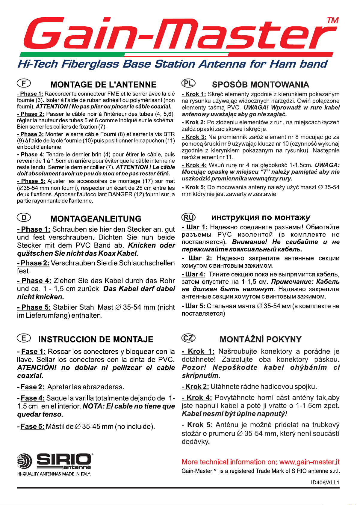
1.Seguire attentamente le istruzioni di montaggio sul foglio illustrativo allegato al
2.Collegare il palo di sostegno a terra utilizzando una trecciola in rame con una
3.Assicurarsi del corretto serraggio di dadi e viti.
4.Se necessario (zone molto ventose o palo di sostegno molto lungo) si consiglia
5.NON SOSTARE vicino all’antenna mentre sta trasmettendo.
6.Si consiglia di rispettare sempre la potenza massima stabilita dalle norme vigenti
7.Attaccare sul palo di sostegno l’etichetta autoadesiva “PERICOLO” contenuta
FR
guanti in gomma, maglia con manica lunga)
che l’antenna, il palo, il cavo e i fili di metallo sono ottimi conduttori di elettricità.
Anche il contatto più lieve di una di queste parti alle linee dell’alta tensione provoca
un collegamento elettrico dalla linea all’installatore attraverso l’antenna.
elettricità, NON TOCCATELA. Chiamate gli operatori della società elettrica,
sapranno rimuoverla in modo sicuro e corretto.
prodotto.
sezione di almeno 6 mm .
l’utilizzo di tiranti di controventatura.
nella confezione in posizione visibile (altezza occhi).
2
FICHE D'INFORMATION SUR LA SÉCURITÉ
ATTENTION
L’INSTALLATION DE CE PRODUIT PRES DE LIGNES A
HAUTE TENSION EST DANGEREUSE. POUR VOTRE
SECURITE, SUIVEZ LES INDICATIONS JOINTES
SIRIO antenne n'assume aucune responsabilité en cas d'installation
défectueuse ou dangereuse. Il ya du personnel disponible, compétent et
expérimenté pour aider à l'installation, l'entretien ou le démontage.
Contactez votre installateur local si une consultation ou une assistance est
requise.
1. Si vous installez une antenne pour la première fois, pour votre sécurité, faites
appel à l’ASSISTANCE PROFESSIONELLE. Consultez votre revendeur qui
pourra vous expliquer quelle méthode de montage utiliser pour la taille et le type
d’antenne que vous souhaiter monter.
2. Choisir un endroit d’installation sûr, la distance de sécurité des lignes à hautes
tensions doit être au moins deux fois la hauteur de l’antenne et du mât. RAPPEL:
LES LIGNES A HAUTE TENSION ET LES LIGNES TELEPHONIQUES SE
RESSEMBLENT. POUR VOTRE SECURITE, VERIFIER QU’AUCUNE LIGNE
NE PUISSE VOUS TUER. Quand vous installez votre antenne, REPPELEZ-
VOUS:
a)NE PAS utiliser d’échelle métallique,
b)NE PAS travailler un jour humide ou venteux,
c)ETRE BIEN HABILLE (chaussures et talons en caoutchouc, gants en
3.Si l’assemblage commence à tomber, s’en éloigner et le laisser tomber. Rappelez
caoutchouc, chemise à manches longues ou veste).
vous que l’antenne, le mât, le câble et les files de fer sont d’excellents
conducteurs de courant électrique. Même le plus léger contact d’une de ces
pièces avec une ligne à haute tension peut créer un contact électrique à travers
l’antenne et l’istallateur.
4.Si l’une des parties de l’antenne vient à être en contact avec une ligne à haute
tension, NE RIEN TOUCHER, NE PAS ESSAYER DE DEMOTER VOUS MEME,
APPLEZ VOTRE AGENCE D’ELECTRICITE qui démontera l’antenne avec
précaution.
INSTRUCTIONS GENERALS pour antennes avec mâts:
1.Suivre avec attention les instructions de mountage du produit.
2.Brancher votre mât à la masse en utilisant un fil de cuivre d’une section minimale
3.Faire attention au bon serrage des écrous et vis.
4.Si nécessaire ( endroits venteux ou mât très longs) l’utilisation de haubans est
5.Quand votre antenne est en mode TX (transmission) NE PAS rester à côté.
6.Il est recommandé de respecter strictement la puissance maximale établie par la
7.Coller l’étiquette autocollante «ATTENTION» jointe à l’antenne sur votre mât à
DE
2
de 6 mm .
recommandèe.
loi.
hauteur des yeux.
SICHERHEITS-INFORMATIONSBLATT
WARNUNG
DIE INSTALLATION DIESES PRODUKTS IN DER NÄHE VON
STROMLEITUNGEN IST GEFÄHRLICH. BEFOLGEN SIE ZU
IHRER SICHERHEIT DIE FOLGENDEN ANWEISUNGEN.
SIRIO Antenne übernimmt keine Haftung, wenn fehlerhafte oder gefährliche
Installationspraktiken angewandt werden. Es steht geschultes und
erfahrenes Personal zur Verfügung, um Sie bei der Installation, Wartung
oder Demontage zu unterstützen. Kontaktieren Sie Ihren Fachhändler,
wenn Beratung oder Unterstützung erforderlich ist
1.Wenn Sie zum ersten Mal eine Antenne installieren, sollten Sie sich von Ihrem
Fachhändler beraten lassen. Er kann Ihnen erklären, welche Montagemethode für
die Größe und den Typ der Antenne, die Sie montieren wollen, zu verwenden ist.
2.Wählen Sie Ihren Installatiosort unter dem Gesichtspunkt der Sicherheit aus. Der
Sicherheitsabstand von Stromleitungen sollte mindestens das Doppelte der
gemeinsamen Länge von Antenne und Mast betragen. OFT KÖNNEN SIE ALS
LAIE ELEKTRISCHE STROMLEITUNGEN UND TELEFONLEITUNGEN NICHT
UNTERSCHEIDEN. - GEHEN SIE ZU IHRER EIGENEN SICHERHEIT
ZUNÄCHST EINMAL DAVON AUS, DASS JEGLICHE LUFTLEITUNGEN SIE
TÖTEN KÖNNTE !! Wenn Sie Ihre Antenne installieren, DENKEN SIE DARAN:
a)Verwenden sie keine Metall-Leiter.
b)Führen sie diese Arbeiten, wenn möglich, nicht an regnerischen oder
stürmischen Tagen aus.
c)Achten sie auf richtige Kleidung: (Schuhe mit Gummisohlen und -
absätzen, Gummihandschuhe, Hemd bzw. Jacke mit langen Armen).
3.Sollte bei der Montage Antenne oder Mast aus irgendwelchen Gründen hinfallen,
sollten Sie diese in diesem Moment nicht mehr berühren. Denken Sie daran, daß
Antenne, Mast, Kabel und metallische Verankerungsdrähte ausgezeichnete
Leiter von elektrischen Strom sind. Selbst die leichteste Berührung dieser Teile mit
einer Stromleitung erzeugt einen elektrischen Stromkreis und kann Sie sofort
töten.
4.Wenn irgendein Teil des Antennensystems mit einer Stromleitung in Kontakt
kommen sollte, BERÜHREN SIE ES NICHT UND VERSUCHEN SIE NICHT, ES
SELB ST ZU E NT FERNEN. R UFEN S IE IHRE Ö RTILICH E
ELEKTRIZITÄTSGESELLSCHATF AN. Die Fachleute dieser Gesellschaften
werden das Problem sicher und gefahrlos lösen.
ALLGEMEINE MONTAGEANWEISUNGEN FÜR ANTENNEN, DIE AUF EINEM
MAST MONTIERT SIND:
1.Befolgen Sie sorgfältig die Montageanweisungen des Produkts.
2.Verbinden Sie Ihren Mast mit einem guten Erdungspotential, indem Sie einen
Kupferdraht mit einem Querschnitt von mindestens 6 mm verwenden.
3.Achten Sie auf den korrekten Sitz von Muttern und Schrauben.
4.Wenn notwendig (Gegenden mit häufigen starken Winden bzw. Stürmen oder
sehr hohe Masten) wird die Verwendung von speziellen Abspannseilen (Erhältlich
im guten Fachhandek) empfohlen.
5.Halten Sie sich nicht in der Nähe Ihrer Antenne auf, während Ihr Funkgerät im
Sendemodus ist.
6.Es wird empfohlen, die gesetzlich fesgelegte maximale Leistung des Funkgerätes
nicht zu überschreiten.
7.Kleben Sie das der Antenne beiliegende selbstklebende Etikett “ACHTUNG” in
Augenhöhe an Ihren Mast.
SAFETY SHEET ID416 3/4 Rev.AINFORMATION
2
Page 4
ES
HOJA DE INFORMACIÓN DE SEGURIDAD
LA INSTALACIÓN DE ESTE PRODUCTO CERCANO A UNA
LÍNEA DE ALTA TENSIÓN PUEDE SER PELIGROSO. SIGA
ATENTAMENTE LAS INSTRUCCIONES PARA SU SEGURIDAD.
ATENCION
Antenne no asume ninguna responsabilidad si se efectúan acciones
SIRIO
irresponsables o peligrosas en el momento de la instalación. Hay personal
disponible, capacitado y con la experiencia necesaria para ayudar o realizar
el mantenimiento, montaje y desmontaje. Póngase en contacto con su
instalador local si precisa asesoramiento o asistencia.
1.Si usted pretende instalar una antena por primera vez, déjese aconsejar por un
profesional, consulte en su establecimiento habitual y siga todas sus
recomendaciones.
2.Elija el lugar más seguro para la instalación. La distancia de seguridad con
respecto a la línea de alta tensión, deberá ser al menos dos veces la altura de la
antena, una vez instalada en el mástil. RECUERDE: LAS LÍNEAS DE ALTA
TENSIÓN Y LAS LÍNEAS TELEFÓNICAS SON PARECIDAS. PARA SU
SEGURIDAD MANTENGASE ALEJADO DE ELLAS. Cuando instale la antena,
RECUERDE:
a)NUNCA utilice una escalera metálica
b)NO pretenda instalar la antena en un día con viento, lluvia o nieve.
c)UTILICE ropa y material adecuado (zapatos aislantes con suela de
3.Si la instalación no está bien efectuada, ésta podría caer, ocasionar grandes
4.Si una parte de la antena entrara en contacto con algún cable eléctrico ALEJESE
INSTRUCCIONES GENERALES
1.Siga atentamente las instrucciones de la hoja ilustrativa que acompaña al
2.Si tiene alguna duda NO prosiga con la instalación. Consulte personal
3.Derive a tierra el mástil de sujeción mediante un cable de 6mm . de sección
4.Verifique que los tornillos y tuercas han sido debidamente fijados.
5.Si es necesario (zonas de mucho viento o mástiles muy largos) utilice tirantes de
6.NO PERMANEZCA cerca de la antena mientras se está transmitiendo.
7.Se aconseja siempre respetar la potencia máxima establecida por las normas
8.Coloque en el mástil la etiqueta autoadhesiva “PELIGRO” suministrada con la
PL
goma, guantes de goma, camisa de manga larga)
desperfectos e incluso causando daños a terceros. Le recomendamos proceda
con extremada precaución.
INMEDIATAMENTE. Llame urgentemente a la compañía eléctrica, NO intente
resolver por su cuenta el incidente. Ellos sabrán solucionar el problema de un
modo correcto y seguro.
producto.
cualificado
mínimo.
vientos.
vigentes
antena, situela en un lugar lo suficientemente visible. (Altura de la vista)
2
KARTA INFORMACJI BEZPIECZEŃSTWA
INSTALOWANIE ANTEN W POBLIŻU LINII WYSOKIEGO
NAPIĘCIA JEST NIEBEZPIECZNE !
UWAGA
SIRIO Antene nie ponosi żadnej odpowiedzialności w razie awarii instalacji w
wyniku błędnego zamontowania lub stosowanych niebezpiecznych praktyk. W
przypadku problemów podczas montażu należy skontaktować się z
przeszkolonym i doświadczonym personelem jak i w celu konserwacji czy
demontażu.
1.Montując antenę po raz pierwszy, dla własnego bezpieczeństwa, poproś o
pomoc specjalistów.
2.Wybierz starannie miejsce montażu w odległości minimum 2 długości anteny
plus masztu od linii energetycznej. Nie używaj metalowej drabiny, załóż buty z
gumowa podeszwą, rękawiczki, koszulę z długim rękawem i nie pracuj w złych
warunkach pogodowych.
3.Jeżeli montowana konstrukcja zaczyna się przewracać nie podtrzymuj jej.
4.Jeżeli część instalacji już dotknęła kabli z prądem nie usuwaj jej sam tylko
zadzwoń od zakładu energetycznego.
Podstawowe instrukcje:
1.Zapoznaj się z instrukcją produktu.
2.Uziemij maszt przewodem min. 6 mm ˛.
3.Starannie skręcaj połączenia.
4.Używaj odpornych na wiatr elementów masztu.
5.Nie przebywaj w pobliżu anteny podczas nadawania.
6.Nie przekraczaj limitów mocy.
7.Oznacz instalacje ostrzegawczą nalepką «UWAGA».
информация о безопасности
RU
установка д анного устройства возле
высоковольтных линий электропередачи опасна
для жизни! Следуйте прилагаемой инструкции!
ВНИМАНИЕ
SIRIO Antenne не несет никакой ответственности за
неисправности, произошедшие в результате неправильного
монтажа. Привлекайте обученный и опытный персонал для
оказания помощи в установке, техническом обслуживании,
сборке или разборке. Свяжитесь с вашим местным
установщиком для консультации или помощи, в случае
необходимости.
1. Если Вы устанавливайте антенну в первый раз, найдите
профессионального помощника. Ваш дилер может объяснить Вам
способ установки антенны в зависимости от типа и размера антенны.
2.Тщательно выбирайте место установки. Расстояние до
высоковольтной ЛЭП должно, как минимум, дважды превышать
высоту мачты и антенны. ПОМНИТЕ: высоковольтные ЛЭП, а
также телефонные и другие кабельные линии находятся под
напряжением, которое опасно для жизни!
Во время установки антенны ПОМНИТЕ:
а) не используйте металлическую лестницу;
б) не работайте во влажную и ветряную погоду;
в) наденьте рубашку или куртку с длинными рукавами, обувь на
резиновой подошве, а также используйте резиновые перчатки.
3. Если собираемая часть начинает падать немедленно отойдите в
сторону и не препятствуйте падению. Помните, что антенна, мачта,
кабель и металлические провода являются проводниками
электрического тока. Даже легкое касание любой из составных
частей антенной системы к открытому источнику электроэнергии
может привести к короткому замыканию или поражению
электрическим током.
4. Если одна из частей устанавливаемой антенной системы в результате
падения или по другой причине соприкоснулась с источником
электроэнергии, НЕ ПЫТАЙТЕСЬ САМОСТОЯТЕЛЬНО
УСТРАНИТЬ ЭТО, ПОЗВОНИТЕ В АВАРИЙНУЮ СЛУЖБУ!
ОСНОВНЫЕ ИНСТРУКЦИИ ПО УСТАНОВКЕ АНТЕННЫ НА
МАЧТУ
1. Внимательно следуйте инструкции по установке антенны.
2. Заземлите мачту медным проводом с сечением не менее 6 кв. мм.
3. Установите антенну, обращая внимание на правильность сборки и
надежность затяжки болтов и гаек.
4. Если необходимо (районы с повышенными ветряными нагрузками
или слишком длинная мачта) используйте специальные
противоветровые направляющие.
5. Не находитесь вблизи антенны во время передачи.
6. Рекомендуется использовать максимально разрешенную мощность
передачи в соответствии с законодательством.
7. Наклейте этикетку “ОПАСНО” упакованную вместе с антенной на
мачту, на уровне глаз
BEZPECNOSTNÍ INFORMACNÍ LIST.
CZ
NE MANIPULUJTE S ANTENOU PO BLI Z
ELEKTRICKEHO VEDENI !
VAROVANI
SIRIO nepřebírá žádnou zodpovědnost v případě neodborné či nebezpečné
montáže. Montáž, údržbu nebo demontáž svěřte kvalifikovanémua
odbornému servisu.
1. Pokud nemate s montazi zkusenosti, pouzijte odbornou firmu
2. Pouzivejte ochranny oblek
3. Pri istalaci do anteny nevysilejte
4. Pri jakemkoli kontaktu s elektrickym vedenim informujte rozvodne zavody
Zakladni instrukce:
1. Pozorne ctete montazni navod
2. Antenni stozar uzemnete vodicem 6mm
3. Zvysenou pozornost venujte kontaktum a spojum
4. Nemontujte antenu v extremne nepriznivem pocasi
5. Pri vysilani se nedotykejte zarice
6. Nepouzivejte vysi vykon nez je vyrobcem urceno
7. Antenu oznacte stitkem “NEBEZPEÈI”
2
SAFETY SHEET ID416 4/4 Rev.AINFORMATION
Page 5
Hi-Tech Fiberglass Base St ation Antenna for Ham band
TM
HW
S
SIRIO
antenne
Gain-Masterä HW is a
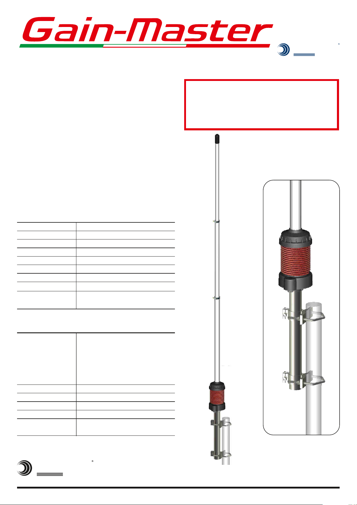
Half Wave high tech
fiberglass base station antenna for 10m to 11m
amateur band made of telescopic fiberglass tubes.
Engineered with the most advanced available
technologies it is completly manufactured in Italy
with high quality materials. The design of the
radiant element works like a central feeded dipole
so all RF currents on the radiator are in-phase and
the ground plane radials are not necessary. The
coaxial coil at the bottom works like RF-choke for
the optimum decoupling from mast and feeding
line.
Electrical Data
Type
Frequency Range
Banwidth @ SWR
Impedance
Radiation
Polarization
Max Gain on the horizon
Max Power
Connector
£
2.0
l
0.5 center feeded vertical dipole
27.2 - 30 MHz (see tunable table pag.3)
1.8 MHz @ 27.2 MHz
W
50
Omnidirectional
Linear Vertical
0 dBd
500 Watts (CW) continuous
UHF-female, PTFE insulator & gold
plated central pin
WARNING
INSTALLATION OF THIS PRODUCT NEAR POWER
LINES IS DANGEROUS. FOR YOUR SAFETY AND
BEFORE YOU BEGIN INSTALLATION, READ THE
SEPARATE SAFETY INFORMATION SHEET.
Mechanical Data
Materials
Wind Resistance
Height (approx.)
Packaging Dimensions
Weight (approx.)
Mounting mast
S
HI-QUALITY ANTENNAS MADE IN ITALY.
SIRIO
antenne
Whip made of white fiberglass three
radiator made of copper wire and low
loss coax cable, stainless steel hardware,
sections composite tube,
anodized AW6060 aluminium,
UV stabilized thermoplastic
up to 160 Km/h; 100 mi/h
5560 mm; 11.2 ft with bracket
1950x100x130 mm; 77x4x5 in
2.6 Kg; 5.7 lb
35-54 mm; 1.4-2.1in
Æ Æ
side mast with “V” bolt
More technical information on: www.sirioantenne.it
Gain-Master is a registered Trade Mark of SIRIO antenne s.r.l.ä
ID442, pag 1/4
Page 6

ITALIANOENGLISH
Gentile Cliente, vogliamo ringraziarla per aver acquistato un
antenna SIRIO Gain-Masterä HW, siamo sicuri che le darà
grandi soddisfazioni perché è stata progettata con le più
avanzate tecnologie attualmente disponibili ed è costruita
interamente in Italia con materiali di elevata qualità.
Gain-Masterä è il concentrato di quarant'anni di esperienza
nel campo delle antenne che ci ha permesso di sviluppare
prodotto unico che rimarrà uno standard di riferimento per
molti anni a venire.
Come funziona Gain-Masterä HW
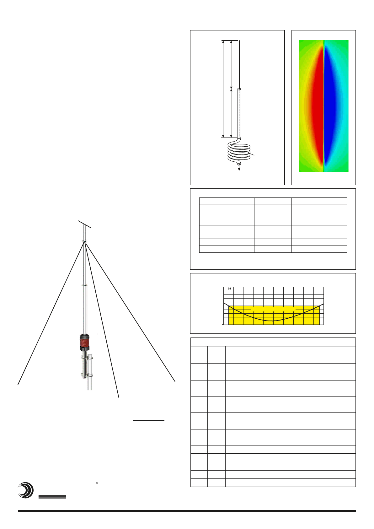
Come mostrato in Fig.1 il segnale RF proveniente dal
generatore percorre il cavo coassiale della bobina d'arresto,
quindi prosegue lungo lo stilo fino ad arrivare alla
terminazione della linea coassiale (centro di fase
dell'antenna). Da questo punto la parte di segnale presente
sul conduttore centrale si propaga lungo la metà superiore
della parte radiante mentre le correnti RF, che viaggiavano
all'interno della schermatura del cavo, fuoriescono scorrendo
all'esterno della schermatura e ridiscendono verso la bobina
d'arresto dove l'elevata impedenza della bobina fa si che si
arrestino (funzionamento equivalente ad un dipolo
alimentato nel suo centro).
In Fig.2 è illustrata la distribuzione di corrente di SIRIO Gain-
Masterä HW. La parte radiante si comporta come un dipolo
alimentato al centro, di conseguenza tutte le correnti RF
risultano in fase e concordi tra loro.
ha permesso di avere un diagramma di irradiazione identico
ad un dipolo con il suo massimo del segnale nel piano
orizzontale. Gain-Masterä HW presenta quindi il massimo
guadagno ottenibile per un'antenna 1/2l e grazie al suo
angolo di radiazione perfettamente orizzontale permette i
migliori collegamenti possibili.
Questo accorgimento ci
Dear Customer, we thank you for purchasing a SIRIO Gain-
Masterä HW antenna, we are sure you will give great
satisfaction because it was designed with the most advanced
technologies currently available and it's entirely built in Italy
with high quality materials.
Gain-Masterä HW is the result of four decades of experience
in the antennas field; that allowed this unique product that will
remain a standard reference for many years to come.
How Gain-Masterä HW works
As shown in Fig.1 the RF signal started from the generator
run through the coaxial cable of the choke coil, then continue
along the first part of the whip until it meet the termination of
the coaxial line (antenna phase centre).
At this point, the signal on the inner conductor propagates
along the upper half of the radiation element. The RF current
travelling inside the cable shield, protruding outside the
screen and descend toward the choke coil where the high
impedance stop it (in fact, it's equivalent to a centre-fed
dipole).
Fig.2 shows the current distribution of SIRIO Gain-Masterä
HW. The design of radiant element behaves as a centre-fed
dipole, hence all currents are in phase.
This arrangement allowed us to have a radiation pattern
equal to a dipole which has its maximum gain on the horizon.
Gain-Masterä HW has the highest available gain for 1/2l
antenna and due to its angle of radiation perfectly horizontal,
enables the best possible connections.
Altri vantaggi di Gain-Masterä HW sono:
E' realizzata e assemblata completamente in Italia con i
migliori materiali disponibili, a partire dallo stilo che è
realizzato in tre sezioni da 1.92m di tubi telescopici compositi
in fibra di vetro con parete a triplo strato che rende Gain-
Masterä HW molto più resistente e rigida rispetto alle
concorrenti.
Non necessita di radiali ground plane in quanto è un antenna
bilanciata che funziona come un dipolo alimentato al centro.
Grazie alla sua bobina di arresto (RF-Choke) posta alla base,
Gain-Masterä HW risulta perfettamente disaccoppiata dalla
sua struttura di sostegno (pali, tralicci, etc.) con il beneficio di
mantenere inalterati sia l'impedenza che il diagramma di
irradiazione.
Può essere tarata nella banda da 27.2 a 30 MHz tramite
tabella di sintonia.
Accetta una potenza massima continuata di 500Watts RMS.
Other Gain-Masterä HW advantages are:
It's completely made and assembled in Italy with the finest
materials available, starting from the whip which is carried out
in three sections of 1.92m telescopic tubes with triple-layer
fibreglass.
It makes Gain-Masterä HW much more durable and rigid
then the competitors.
It does not require ground plane radials because it is a
balanced antenna that function as a centre-fed dipole.
Thanks to it's cable coil (RF-Choke) at the base, Gain-
Masterä HW is fully decoupled from its supporting structure
(poles, towers, etc.) with the benefit of preserving both the
impedance that the radiation pattern.
It can be tuned in the range from 27.2 to 30MHz using the
tuning table.
It accepts a maximum continuous power of 500Watts RMS.
S
HI-QUALITY ANTENNAS MADE IN ITALY.
SIRIO
antenne
More technical information on: www.sirioantenne.it
Gain-Master is a registered Trade Mark of SIRIO antenne s.r.l.ä
ID442, pag 2/4
Page 7
Gain-Masterä HW Technical Informations
SAFETY FIRST:
COMES NEAR ELECTRIC POWER LINES.
DOING INSTALLATION, READ THIS MANUAL AND THE
SUPPLIED SEPARATE SAFETY MULTI LANGUAGE
INFORMATION SHEET.
SUGGESTION: We recommend to assemble the antenna on
a flat ground open area. U
H1000R, AIRCOM PLUS or RG-213 as short as possible to
get the best performance and we recommend to mount your
antenna at minimum 3 meters above the roof, as far as
possible from walls, power lines and other antennas.
TROUBLESHOOTING: Gain-Master HW is a tunable
antenna. It is factory checked one by one. If you are unable to
obtain an accettable SWR reading from your antenna, follow
these suggestions to try to solve the problem.
YOU CAN BE KILLED IF THIS ANTENNA
BEFORE
se a good coax cable like BELDEN
Schematic diagram
=
Electrical Length
1/2 or 0,5 l
=
RF current
# Check the coaxial cable and all its connections. Be sure that
the cable is not pinched, shorted, broken or kinked.
# Check if the equipments (CB radio and SWR-meter) work
properly. Make use of owner’s manual for assistance in
operating it.
# Be sure that the antenna is installed at least 3 meters above
the roof of the nearest building and 5-6 meters above or
away from any metal objects in the area.
Low Loss
Coaxial RF choke
To RF generator
Fig.1
TUNING TABLE
Frequency (MHz)
27.2
27.5
28.0
10m band 28.5
29.0
29.5
30.0
NOTE: Use the table just as a guide. For
fine-tuning please use an SWR-meter
S.W.R.
Model: Gain-Master HW
3.0
2.8
2.6
2.4
2.2
2.0
1.8
1.6
1.4
1.2
1.0
26.2
L = (mm)
1820
1783
1734
1692
1647
1611
1550
TYPICAL S.W.R. RESPONSE
1.8 MHz band @ SWR=2
27.2
Band @ SWR=2
26.6 ÷ 28.4 MHz
27.1 ÷ 28.9 MHz
27.6 ÷ 29.4 MHz
28.0 ÷ 30.0 MHz
28.5 ÷ 30.5 MHz
29.0 ÷ 31.0 MHz
Fig.2
File: F-01-031
f.(MHz)
MHz26.3 ÷ 28.1
28.2
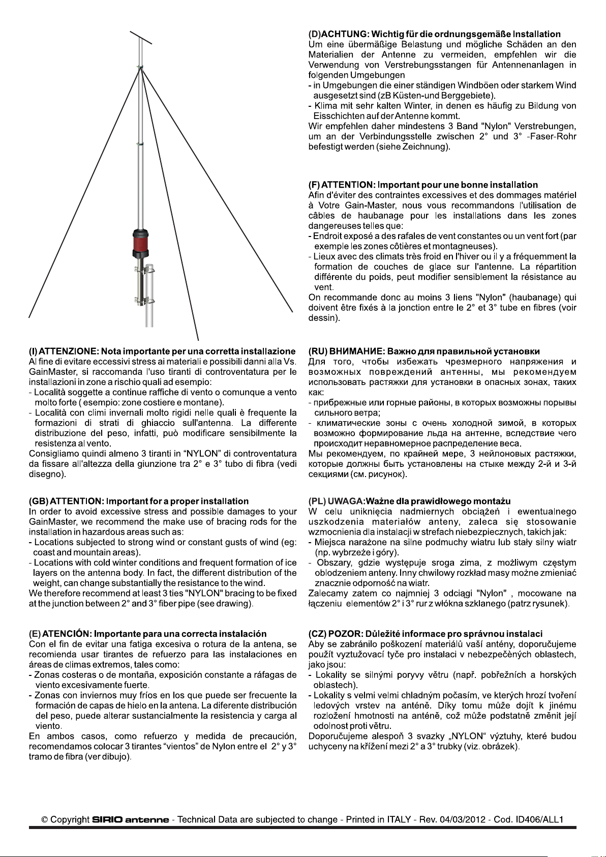
ATTENTION: Important for a proper installation
In order to avoid excessive stress and possible damages to your
GainMaster, we recommend to make use of bracing rods for the
installation in hazardous areas such as:
- Locations subjected to strong wind or constant gusts of wind (eg:
coast and mountain areas).
- Locations with cold winter conditions and frequent formation of ice
layers on the antenna body. In fact, the different distribution of the
weight, can change substantially the resistance to the wind.
We therefore recommend at least 3 ties "NYLON" bracing to be fixed
at the junction between 2° and 3° fiber pipe (see drawing).
S
HI-QUALITY ANTENNAS MADE IN ITALY.
SIRIO
antenne
Parts List
Pos Q.ty Part No Description
11SL06600 Wired coaxial radiator
21- Bottom section with coil
31CH01407 8mm open key
41CF02117 15.4x19x1920 fiberglass tube
5
1CF02217 19.5x23.5x1920 fiberglass tube
6
2FA00200 Ø 16-27mm AISI316 hose clamps
7
1TE07300 Ø 18.8x17 radiator fixing part
8
1VT05900 M4x6 AISI304 set screw cone point
1CH00800 2 mm Allen key
9
10
11
12
13
14
15
16
1
TE05616
IE560/USA
1
2
VT01300 M6x20 AISI304 exagonal head screw
2ST04500 Extruded aluminium bracket
2TI03100 M6x188 AISI304 V-bolt
6
DA01400 M6 AISI304 hexagonal nut
6RO04200 M6 AISI304 spring lock washer
Ø 18.8 PVC top cap
self-adhering “DANGER” label
More technical information on: www.sirioantenne.it
Gain-Master is a registered Trade Mark of SIRIO antenne s.r.l.ä
ID442, pag 3/4
Page 8
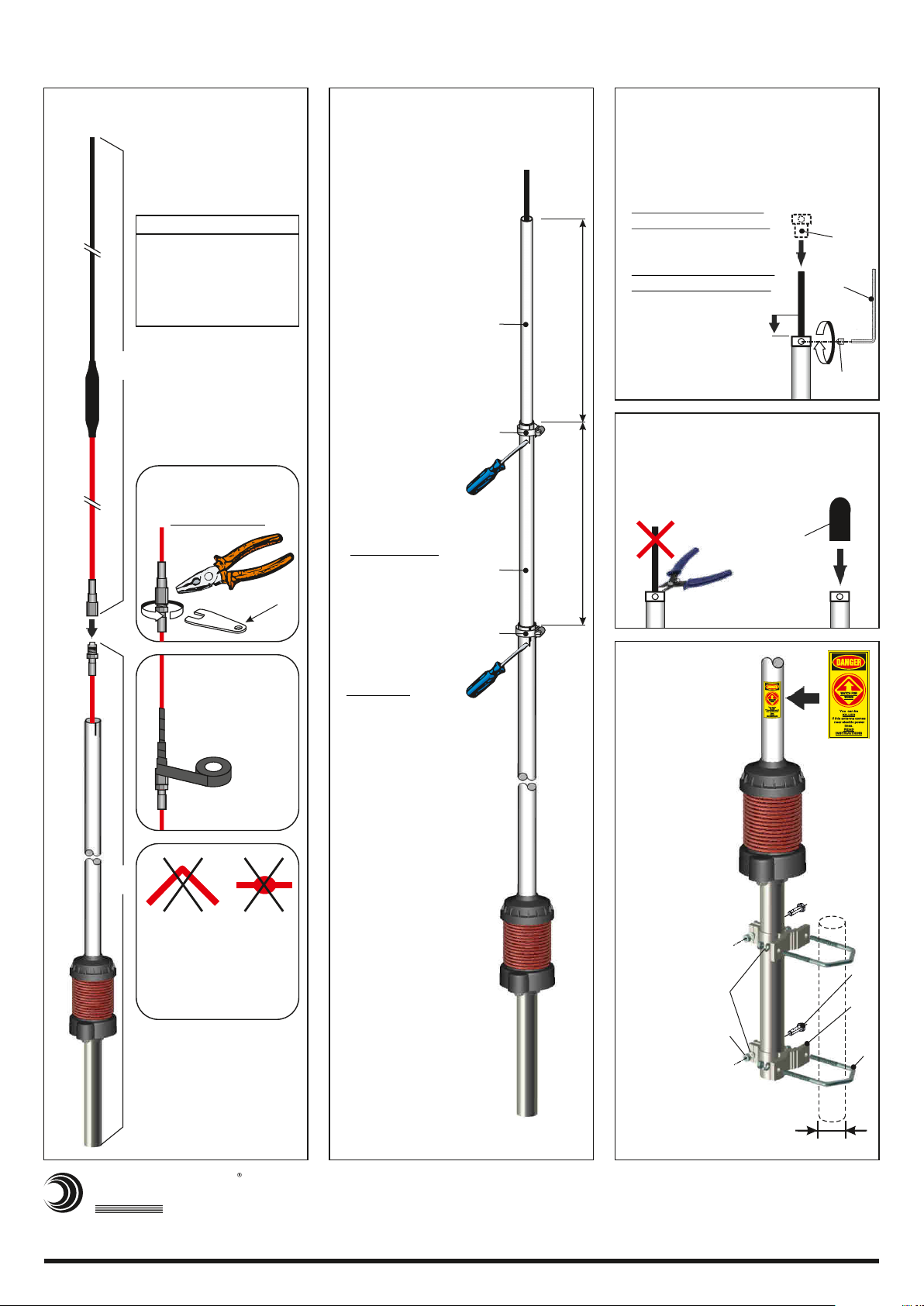
Gain-Masterä HW Mounting Instructions
Fase/Step 1
· Connessione del cavo
radiante
Connection of wired
radiator
Mounting needed tools:
n. 1 tape rules (meter)
n. 1 screwdriver flat point
n. 1 10 mm open jaw wrench
n. 1 plier
n. 1 electrical PVC tape
n. 1 nippers
1
Avvitare i connettori
BEN SERRATI!
Screw on the connectors
WELL LOCKED!
Sigillare entrambi i
connettori con nastro
adesivo in PVC
Seal both connectors
with electrical
PVC tape
Fase/Step 2Fase/Step 3
Infilare parte 7 sul cavo fino in battuta
Inserimento tubi sul cablaggio
·
Insert the tubes on wiring
Scegliere la frequenza
·
di lavoro dalla Tabella di
Taratura a pag.3, quindi
posizionare i tubi alla
lunghezza *L
corrispondente
Choose the working
frequency from the
Tuning Table on
page 3, then place
the tubes to length
*L corresponding
4
*L
6
Serrare le fascette
·
6 fino al bloccaggio
dei tubi in fibra 4 e 5.
ATTENZIONE: un
serraggio eccessivo
può provocare
3
crepe e danni ai
tubi in fibra.
Tighten the clamps
6 up to the locking
of the fibererglass
tubes 4 and 5.
CAUTION: A
over-tightening
it may cause cracks
and damage at the
fiberglass tubes.
5
6
*L
·
Insert part 7 on cable until it stops
Tendere il cavo quindi farlo
·
rientrare di 1÷1.5cm.
NOTA: IL CAVO NON
DEVE ESSERE TESO
Pull up the cable then
return down 1÷1.5cm.
REMARK: THE CABLE
MUST NOT BE TIGHT
Bloccare con forza
·
il cavo con vite 8 e
chiave 9
Lock strongly the
cable with screw
8 and key 9
1÷1.5cm
Fase/Step 4
Tagliare il cavo in eccesso
·
Cut the extra cable
·
Installare il cappuccio in PVC
Instal the PVC cap
10
Fase/
Step 5
· Applicare
l’etichetta
DANGER in un
punto visibile
Apply the
DANGER
sticker in a
visible point
7
9
8
11
2
ATTENZIONE!
Non piegare o schiacciare
il cavo coassiale
ATTENTION!
Do not bend or pinch
the coaxial cable.
16
15
Robusto palo di montaggio
Æ 35-54mm (non fornito)
*L = see Tuning Table pag.3
S
HI-QUALITY ANTENNAS MADE IN ITALY.
SIRIO
antenne
More technical information on: www.sirioantenne.it
Gain-Master is a registered Trade Mark of SIRIO antenne s.r.l.ä
B Copyright SIRIO antenne - Technical Data are subjected to change - Printed in ITALY - Rev. 09/02/2016 - Cod. ID442, pag. 4/4
Strong steel mast
Æ 35-54mm (not supplied)
12
13
14
Page 9
Page 10
 Loading...