

Sirge KFR-25GW,KFR-25GVWa Service Manual

I
Split Wall-Mounted Type
Air-Conditioners
Service Manual
KFR-25GW/VWa

CONTENTS
I. Photo of the Production ··············································································· 2
II. Operating Principle ······················································································ 3
III. Exploded Views of the Production ······························································ 5
IV. List of common wearable parts···································································· 8
V.
Main Technical Data and Cooling and Heating Characteristic
Curver ··············
8
VI. Dismantling Procedure ················································································· 11
VII.
Fault Analysis of the Product Available and Typical
Examples ························································
14
1
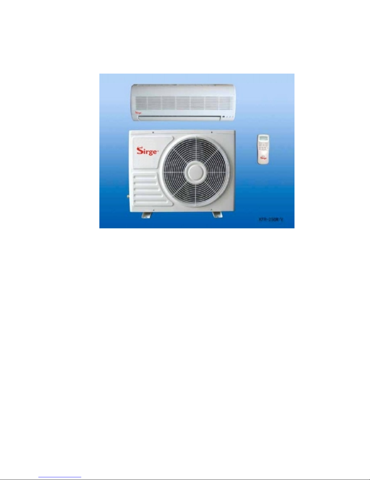
I Photo of the production
Feature:
1. Stylish and deluxe design
2. Compact size, easy to install and operate
3. Sends out air in gentle stream for physical comfort
4. Use multi-fold evaporator to create the area of heat exchange
5. Intelligent blur defrost
6. Remote control
2

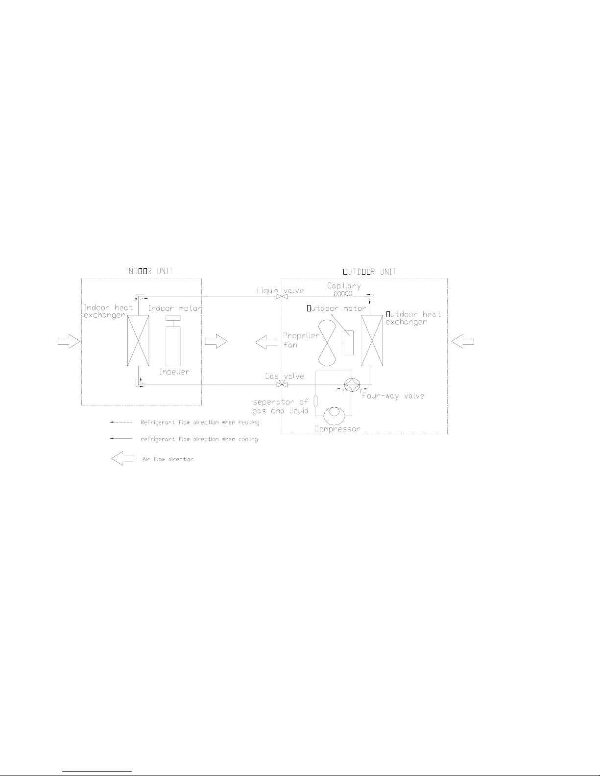
II Operating P rinciple
A. Cooling
After the power suppl y is switched on, the m achine is set to COO L mode. With the
compressor being operated, the low-temperature and low-pressure refrigerant vapor is
sucked into the compressor where it is turned into high-temperature and high-pressure
gas. Then it is cooled down in the outdoor heat ex changer b y the air a nd becomes
liquid. Af ter be ing thr ottled b y th e capillary, th e r efrigerant liquid c omes into the
indoor unit and then it e vaporates in th e indoor heat, exchanger, absorbing h eat an d
reducing t he room t emperature. The evapo rated refri gerant vapor ret urns t o t he
outdoor unit and is a gain sucked into the compressor, completing the c ycle. With the
refrigerant cycling bein g kept on, the obj ective o f lowering th e room tem perature is
fulfilled.
B. Heating
After the power supply is switched on, the machine is set to HEAT mode and the coil
of the e lectromagnetic four -way v alve is e nergized. Af ter the c ompressor sta rts to
operate, t he hi gh-temperature and hi gh-pressure refri gerant gas fi rst com es i nto t he
heat exchanger of th e in door unit, wher e it is co oled, rele ases h eat and increases the
room te mperature. The c ooled hi gh-pressure re frigerant is the n thr ottle1d in the
outdoor unit and returns to the compressor af ter evaporation. With such c ycles being
maintained, the objective of increasing the room temperature is fulfilled.
C. System Schematic Diagram
Please see the following Diagram
3
4
III Exploded Views of the Production
Detailed part list of KFR-25GW/VWa indoor unit
S/N Part Name Drawing No. Part No.
1 Front panel assy KFR-25G/V.010.00 KFR-25G/VWa 01
2 Air strainer KFR-25G/V.050.00WX KFR-25G/VWa 02
3 Upper frame assy KFR-25G/V.020.00 KFR-25G/VWa 03
4 Right locating cover KFR-23G/T.000.06 KFR-25G/VWa 04
5 Electric box cover KFR-23G/T.000.09 KFR-25G/VWa 05
6 Indoor control board KFR-23W/T101.041.00 KFR-25G/VWa 06
7 Electric box KFR-23W/T.100.01 KFR-25G/VWa 07
8 Step motor KFR-23G/T.061.00WX KFR-25G/VWa 08
9 Transformer KFR-23G/T.100.03WX KFR-25G/VWa 09
10 Indoor motor KFR-25G/V.070.00WX KFR-25G/VWa 10
11 Lower frame assy KFR-25G/V.040.00 KFR-25G/VWa 11
12 Impeller fan KFR-25G/V.080.00WX KFR-25G/VWa 12
13 Water-collecting plate assy KFR-25G/V.030.00 KFR-25G/VWa 13
14 Left locating cover KFR-23G/T.041.04 KFR-25G/VWa 14
15 Fixing clip KFR-23G/T.000.05 KFR-25G/VWa 15
16 Screw ST4*12FT SJ 2823-87 KFR-25G/VWa 16
17 Eavaporator assy KFR-25G/V.060.00 KFR-25G/VWa 17
5
 Loading...