

Siren Players SFGH-100 User Manual

1
SFGH-100 SIREN & FLASHING LIGHT SYSTEM
Installation & Operation
The SFGH-100 is a precision built, full function 100 watt siren system that incorporates both an alternating
headlight and grille light flasher in the same unit. The SFGH-100 draws no current unless a function is
selected, so there is no battery drain. The Amplifier/Flasher unit mounts in the trunk. Quick connection
allows the remotely controlled siren, public address system, air horn, and flashers to be installed easily
and quickly.
PLEASE READ THESE INSTRUCTIONS COMPLETELY BEFORE ATTEMPTING THE INSTALLATION
INSTALLATION
Proceed as follows referring to figure (1) on back page.
1. UNPACKING
A. Carefully remove the control head box, power cable, accessory harnesses, and
Amplifier/Flasher unit from the shipping carton. Remove the speaker from it’s
shipping carton.
2. MOUNTING
A. The Amplifier/Flasher unit should be located in the trunk on the same side of the vehicle as
the battery. Preferred locations are under the rear deck or on the rear seat supports.
Mount the unit using 4 sheet metal screws. Be careful that the screws don’t intrude into the
passenger compartment. Keep in mind the location of connectors P1, P2, and P3 and where
their cables will run. CAUTION: The transistor heatsinks must NOT touch ground. If
possible, the unit should be mounted to a metal surface for adequate ventilation and
heat dissipation.
B. Find a suitable location for speaker mounting, away from heat, moving parts, and as
protected as possible. On some vehicles this can be in front of the radiator, on others
behind the bumper, or between the tire and bumper. Mount the speaker securely, IT IS
HEAVY. Use at least 1/4 x 20 bolts & nuts. Route the plug-in connector into the engine
compartment.
3. POWER CABLE INSTALLATION
A. The power cable included in the SFGH-100 system is equipped with a 12 pin socket on one
end (P2) and butt connectors for the engine compartment, on the other.
B. Find a large grommet, or drill a 1 1/4” hole in the vehicle’s firewall on the same side as the
battery. If a hole was drilled use a grommet or snap bushing to protect the cable. Route
the cable to the trunk, leaving the WHITE sense wire in the front seat area for later connec tion. Plug the power cable into its’ mating connector (P2) on the Amplifier/Flasher unit.
Be sure to leave enough slack in the cable at the connector so the plug can’t pull out.
C. The black ground wire should be connected to the vehicles chassis with a sheet metal screw
and star type lock washer under the terminal. Make sure it is a good clean connection.
D. Route the speaker wire to the brown and blue/black wires in the power cable and butt connect
them together.
2
E. Butt connect the battery cable wires to the red and red/black wires on the power cable. Route
cable to the battery and connect to the positive (+) terminal, or an auxiliary terminal block as
provided some vehicles.
F. WHITE WIRE (Ignition Sense) is routed to the fuse block or other ignition source. This wire
must see +12 volts when the key is turned on or the SFGH-100 will not operate.
CAUTION: The battery cable connector and ignition sense lead are both fused for the SFGH-100’s
protection. The battery cable fuses are 20 amp. and the ignition sense uses a 3 amp. fuse. Both are
standard ATO type. NEVER REPLACE A FUSE WITH ANYTHING BUT THE PROPER SIZE. SERIOUS
DAMAGE COULD RESULT.
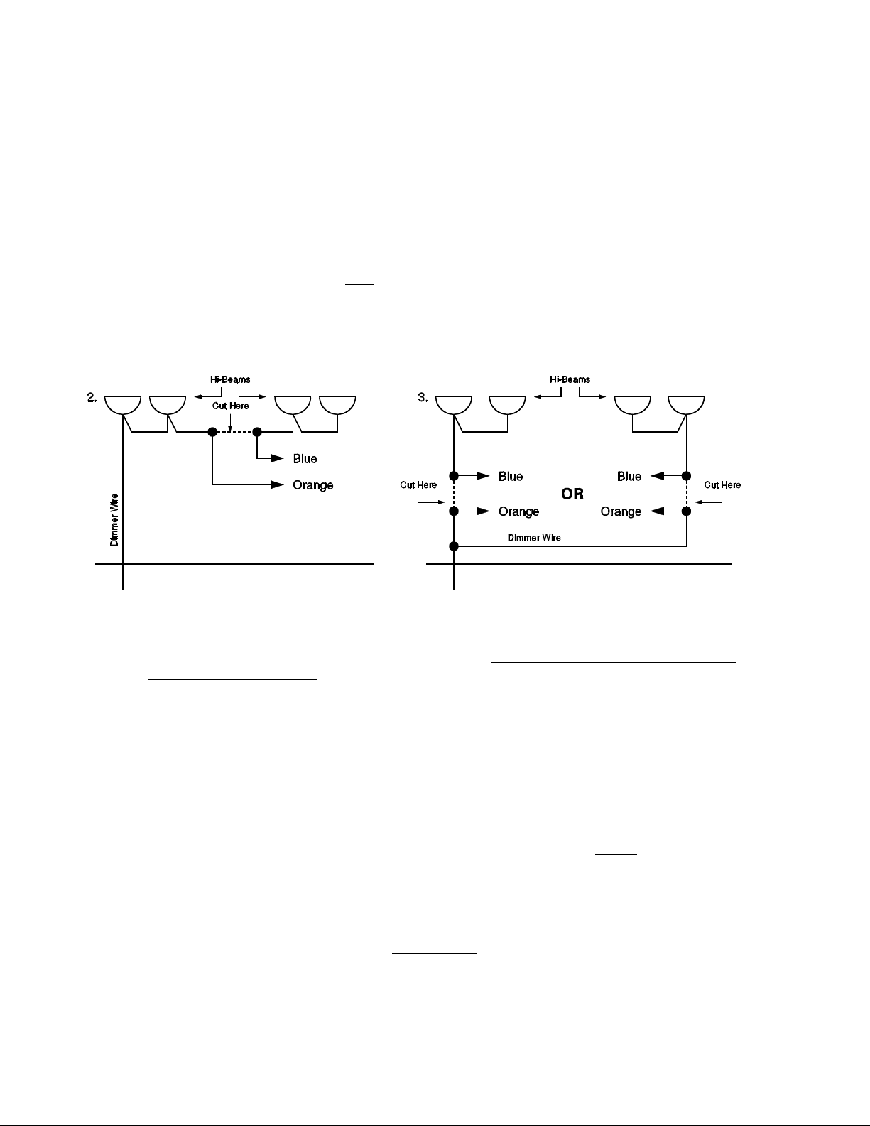
G. Refer to figures 2 & 3 below. The SFGH-100 flasher splices into the headlight circuit at a
single point, and this point is after the headlight wire harness split between the Headlights.
The BLUE & ORANGE wires in the flasher harness may be installed in either leg of the
headlight wiring as shown.
Figures 2 & 3 Location of Slice into Hi-Beam Headlight Wiring:
H. Alternating lights such as grille lights or deck lights (Caution: 8 amps. maximum ) may be
connected to the BLACK and YELLOW wires from the flasher harness.. Use silicone filled butt
connectors and be sure to make solid connections. If Not Used the Yellow and Black wire
MUST NOT touch ground.
4. CONTROL HEAD & CABLE INSTALLATION
A. Find a location from which the SFGH-100 Control Head can easily be operated, and
concealed if necessary. If the Control Head mounting bracket is used, mount it to the Control
Head using the 6-32 x 3/8” thread cutting screws provided. Carefully mount the bracket.
B. Route the 12-pin plug (P1) under the carpet to the trunk, and plug it into the Amplifier/
Flasher unit P1 connector. Be sure to strain relieve the cable.
C. If radio rebroadcast is desired, connect the 22ga. zip cord provided across the speaker
terminals of the radio to be monitored. The rebroadcast feature can be disabled by
unplugging the in-line 2-pin connector.
OPERATION
Refer to figure 4 below.
All functions of the SFGH-100, except on & off, are controlled from a small Control Head. The vehicles
key will turn the unit on & off. The SFGH-100 draws no current unless a function is activated.
Control Head functions are as follows:
 Loading...