

Siqura XSNet C6108SW Quick Start Manual
Page 1
XSNet C6108SW
Quick Start guide
1 Unpacking
Unpack the items. Your package should
include:
One XSNet C6108SW hardened managed
switch
2 What Else You Need
Category 5 or better cable for RJ-45 ports
SFP module and corresponding fiber cables
for SFP slot.
PC with a DB9 straight cable
3 Select a Location
DIN-Rail, wall, and rack mount installation
Identify a power source within 6 feet (1.8
meters).
Choose a dry area with ambient temperature
between -40 and 75ºC (-40 and 167ºF).
Keep away from heat sources, sunlight, warm
air exhausts, hot-air vents, and heaters.
Be sure there is adequate airflow.
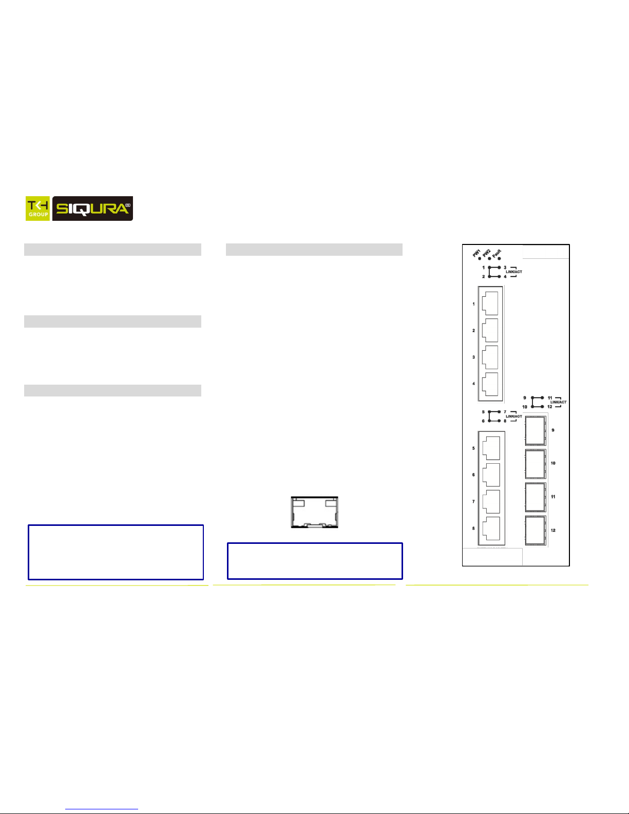
4 Connect to the Data Ports
The managed switch is equipped with the
following ports:
Eight 10/100/1000BASE-TX ports
Four 1000BASE SFP slots
10/100/1000BASE-TX Ports
These ports can connect to devices such as
an IP surveillance camera or a Voice Over
Internet Protocol (VoIP) phone.
A. Insert one end of an appropriate cable into a
switch port. x
B. Connect the other end into the Ethernet port
of the device.
C. Repeat steps A and B for each additional
device you want to connect to the switch.
1000BASE SFP Slots
Insert the SFP module and connect the
appropriate fiber cabling
Note that XSNet Series manuals may cover
multiple models. To establish if a particular
feature or specification in this manual
applies to the unit at hand, consult the
datasheet of the given model.
Note: The EU Declaration of Conformity for
this product can be found at
www.siqura.com/support-files.
XSNet C6108SW
Page 2
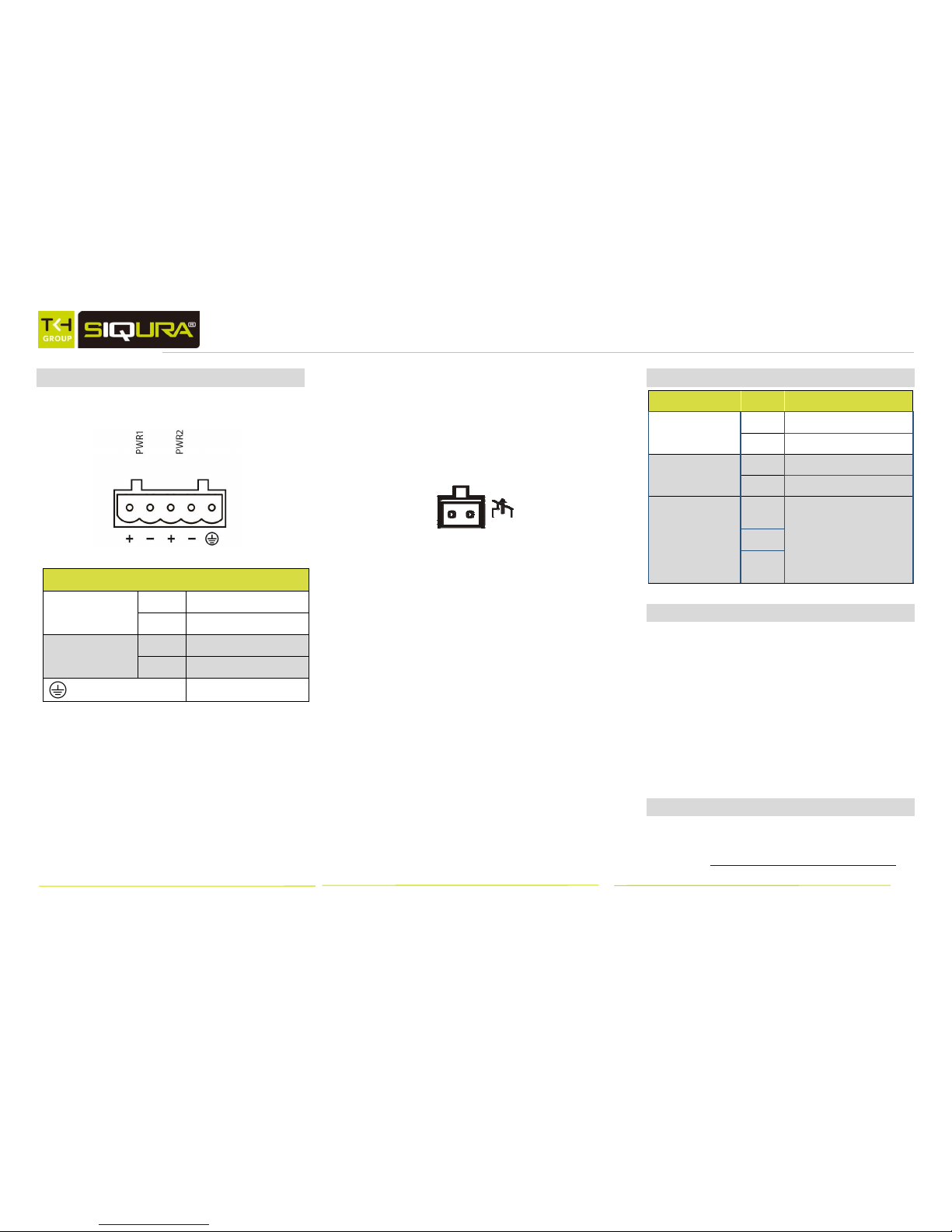
5 Connect Power
There are two DC power inputs on the
terminal block as shown below:
Pin
Description
Power 1
+
12 – 48V DC
-
Power Ground
Power 2
+
12 – 48V DC
-
Power Ground
Earth Ground
Power Consumption: Max 20 Watts
The Fault LED indicator will light up to if
either Power 1 or Power 2 ceases to
function. However, the switch will
continue to work normally even if the fault
LED is lit, as long as the other power
source is functioning.
Relay Output Alarm
The switch provides relay output contacts
for signaling of a user-defined power or
port failure. The relay output can be
connected to an alarm signaling device.
Current is 1A at 250VAC.
Power-Up Sequence
When you apply power:
All Link/ACT LEDs blink momentarily.
The Power 1, 2 LEDs will light up to indicate
which power inputs are connected.
LEDs for every port connected to a device
will flash, as the switch conducts a brief
Power On Self-Test (POST).
6 LED Status Indicators
LED
State
Status Indication
Power 1, 2
Steady
Power on
Off
Power off
Alarm
Steady
Power input failure
Off
Power normal
Link/ACT
(10/100/1000TX)
Steady
Valid network connection
established on TX port
Flashing
Transmitting or receiving data
Off
No network connection
established
7 Alarm Setting
Power and port failure alarms can be
enabled through the web interface, as well
as through the CLI. To use the web
interface to set an alarm, navigate to
Diagnostics → Alarm Setting. Use the
drop-down menu to select the item for
which you want to enable the alarm. Set
the Trigger Enabled field to “YES”, and
click “Update Setting.”
7 Download the Manual
All product-specific manuals and
documents are available as PDF download
at http://www.siqura.com/support-files
 Loading...