

Siqura VBS 2050 TX-3 User Manual
VBS 2050 TX-3
Triple optical video transmitter
USER MANUAL
1. General description
The VBS 2050 TX-3 plug-in module contains three
identical optical video baseband transmitters. Video
input to each of these separate analogue
transmitters is converted into intensity modulated
optical equivalents. Signal integrity is preserved
with the aid of video clamping, making installation
and operation adjustment-free. The units transmit at
an optical wavelength of 1300 nm and can be
connected to single-mode optical fiber.
The 7TE modules will slot into the backplanes of
TKH Security's MC 10 or MC 11 power supply
cabinets; the EB versions of these allow module
status readout from a network.
Details specific to the stand-alone version (/SA
option) are described in a supplementary, separate
document.
VBS 2050 TX-3 transmitters are suitable for use in
combination with ADV systems, allowing
incorporation of two independent streams of digital
data into a video signal.
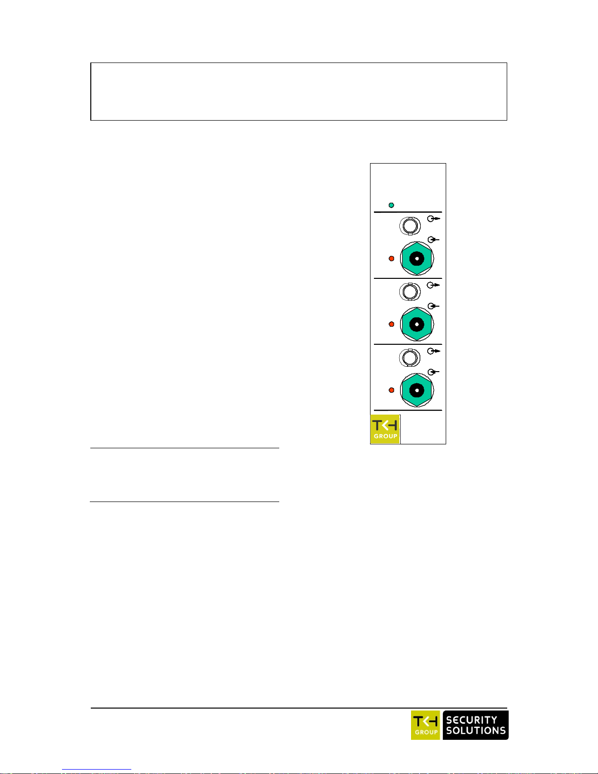
2. Indicators and connectors
Figure 1 shows the signal connection facilities and
indicators on the front panel of a VBS 2050 TX-3
transmitter module (see also table 1).
o
, ST connectors (3x)
Optical output
o
, 75 BNC connectors (3x)
Video input
Status indicator LEDs
* DC
DC power supply
* NV, 3x
No video at input
Table 1. Indications and connectors on the front panel
of the VBS 2050 TX-3
3. Installation instructions
1. VBS 2050 TX-3 units should always be used in
combination with TKH Security power supply
cabinets or in TKH Security stand-alone
housings.
2. Plug the module into the power cabinet (or
connect the power supply of the /SA housing)
and connect suitable video and optical fiber
equipment to the module.
3. After powering on, at least the green DC LED
should glow.
4. Upon feeding a TX-3 input with a proper video
signal, the corresponding NV LED (red) should
go out.
4. Care and maintenance
To maintain reliable operation of the module,
observe the following:
- Prevent dust from collecting on the equipment
- Protect the equipment against moisture
- Maintain sufficient free space around the equipment for cooling.
General safety and EMC information is found in the
final section of this document.
Figure 1.
VBS 2050 TX-3
front panel layout
VBS TX-3
DC
CH1
CH2
CH3
NV
NV
NV
VBS TX-3
DC
CH1
CH2
CH3
NV
NV
NV
© Siqura 2017
Version 002101-3f
VBS2050TX3 (MW10)
2
5. Technical specifications
The technical specifications of the VBS 2050 TX-3
are given in table 2 below.
Optical
Wavelength
1300
nm
Source
LED
Fiber type
9
m
Output level
-28
dBm
System link budget
12
(1)
dB
Video
Video system
PAL/SECAM/NTSC
Input impedance
75
Return loss
30
dB
Input level
1
VPP
Network management variables
Voltages
Module temperature
Alarms
Environmental
Ambient temperature
full performance
+5 to +45
o
C operating
-40 to +74
o
C
Relative humidity
<95 (no condensation)
%
Electrical safety
AL / IEC / EN 60950-1
UL recognition file
E242498
Laser safety
IEC 60825-1, IEC 60825-2
EMC immunity
EN 55024, EN 50130-4,
EN 61000-6-2
EMC emission
EN 55022 (Class B)
FCC 47 CFR 15 (Class B)
Electrical
Power supply voltage
12 (/SA)
Vdc Power consumption
1.7
W
Mechanical
Optical connectors
ST (3x)
Video connectors
BNC (3x)
Outer dims. (h x wx d)
128 x 35 x 190
mm
Weight (approx.)
0.450
kg
1)
With receivers VBS 2040 RX/VBS 2050 RX-3.
Table 2. Technical specifications of the VBS 2050 TX-3
6. Safety, EMC, ESD
General
The safety information contained in this section, and on
other pages of this manual, must be observed whenever this
unit is operated, serviced, or repaired. Failure to comply with
any precaution, warning, or instruction noted in the manual
is in violation of the standards of design, manufacture, and
intended use of the unit.
Installation, adjustment, maintenance and repair of this
equipment are to be performed by trained personnel aware of
the hazards involved. For correct and safe use of the
equipment and in order to keep the equipment in a safe
condition, it is essential that both operating and servicing
personnel follow standard safety procedures in addition to the
safety precautions and warnings specified in this manual, and
that this unit be installed in locations accessible to trained
service personnel only.
Siqura assumes no liability for the customer’s failure to
comply with any of these safety requirements.
UL/IEC/EN 60950-1: General safety requirements
The equipment described in this manual has been
designed and tested according to the UL/IEC/EN 60950-1
safety requirements.
If there is any doubt regarding the safety of the equipment, do
not put it into operation. This might be the case when the
equipment shows physical damage or is stressed beyond
tolerable limits (e.g. during storage and transportation).
Before opening the equipment, disconnect it from all power
sources. The equipment must be powered by a SELV*) power
supply.
When this unit is operated in extremely elevated temperature
conditions, it is possible for internal and external metal
surfaces to become extremely hot.
Optical safety
This optical equipment contains Class 1M lasers or LEDs
and has been designed and tested to meet IEC 608251:1993+A1+A2 and IEC 60825-2:2004 safety class 1M
requirements.
Optical equipment presents potential hazards to testing and
servicing personnel owing to high levels of optical radiation.
When using magnifying optical instruments, avoid looking
directly into the output of an operating transmitter or into the
end of a fiber connected to an operating transmitter, or there
will be a risk of permanent eye damage. Precautions should
be taken to prevent exposure to optical radiation when the
unit is removed from its enclosure or when the fiber is
disconnected from the unit. The optical radiation is invisible
to the eye.
Use of controls or adjustments or procedures other than
those specified herein may result in hazardous radiation
exposure.
The installer is responsible for ensuring that the label
depicted below (background: yellow; border and text: black)
is present in the restricted locations where this equipment is
installed.
The locations of all optical connections are listed in the
Indications and Connectors section of this manual.
Optical outputs and wavelengths are listed in the Technical
Specifications section of this manual.
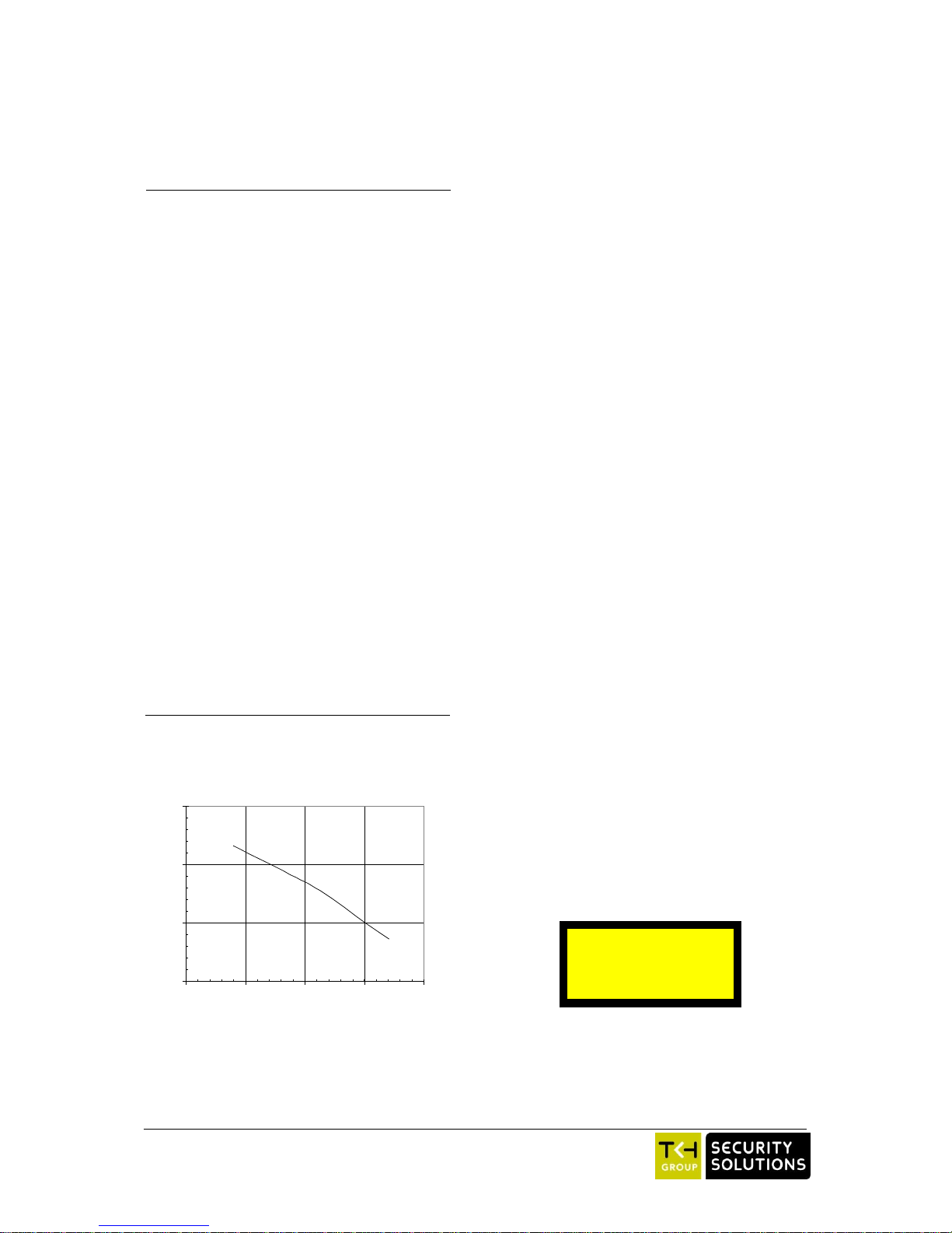
Optical power (dBm)
SNR (dB, weighted)
40
50
60
70
-45-40-35-30-25
Figure 2.
VBS 2040/2050 systems signal-to-noise ratio as
a function of optical level (typical; 1300 nm,
measured with 9 m fibre)
Hazard Level 1M
 Loading...