

Siqura UTF 4200 TX-MSA, UTF 4210 TX-MSA, UTF 4200 RX, UTF 4200 RX-2, UTF 4210 RX User Manual
...
UTF 42xx /Bilinx Series
Optical Video/Data Transmitters/Receivers
USER MANUAL
WARNING
This is a Class A product. In a domestic environment this product may cause radio interference, in which case the user
may be required to take adequate measures. Please read section 6 of this Manual
1. General description
This user manual is valid for the following models:
Model
Description
Housing
UTF 4200 TX-MSA /Bilinx
Transmitter
2 x mm
Stand-alone
UTF 4200 RX /Bilinx
Receiver
2 x mm
Rack-mount
UTF 4200 RX-2 /Bilinx
Receiver
2 x mm
Rack-mount
UTF 4210 TX-MSA /Bilinx
Transmitter
1 x mm
Stand-alone
UTF 4210 RX /Bilinx
Receiver
1 x mm
Rack-mount
UTF 4210 RX-2 /Bilinx
Receiver
1 x mm
Rack-mount
UTF 4250 TX-MSA /Bilinx
Transmitter
1 x sm
Stand-alone
UTF 4250 RX /Bilinx
Receiver
1 x sm
Rack-mount
UTF 4250 RX-2 /Bilinx
Receiver
1 x sm
Rack-mount
UTF 42xx /Bilinx /SA
Stand-alone
Table 1. Models described in this user manual
mm = multimode fiber sm = single-mode fiber
A UTF (Up the FiberTM) transmitter (TX) converts a
composite video signal into a high-quality, 9-bit
digitised optical equivalent and transmits this over
single-mode or multimode optical fiber. All UTF
Bilinx units support the Bilinx protocol. The data
signal is to be put on the coax cable, using suitable
equipment. The bidirectional data link enables camera
control over the same, extended distances as can be
bridged with standard UTF 42xx equipment.
Additionally, the transmitter provides an independent,
voltage-free alarm contact (normally open) for door
contacts and anti-tamper contacts, for example.
Complementary UTF receivers (RX) receive and
convert the optical signal to video/contact closure.
UTF 4200 models use one transmission wavelength
(1300 nm), whereas UTF 4210 and 4250 models use
two (1310 nm and 1550 nm). RX-2 models are dual
units, each subunit capable of communicating with a
separate transmitter.
A wide range of operating temperatures makes the
stand-alone transmit ter suitable for use within outdoor
camera housings and camera connection boxes (see
datasheet).
The TX MSA miniature, stand-alone transmitter can be
powered by the camera power supply (12-24 Vdc or
24 Vac) or by a PSA/PSR 12 DC.
If 24 VAC is used, read section 3 first.
For operation under extreme environmental conditions,
the PSR 12 DC is recommended.
The UTF receivers (RX, RX-2) are designed for use in
a TKH Security MC power supply rack. The UTF
42xx/SA are the stand-alone versions of the rackmounted models. UTF 42xx systems are SNM
compatible.
The general connection layout is given in figure 1.
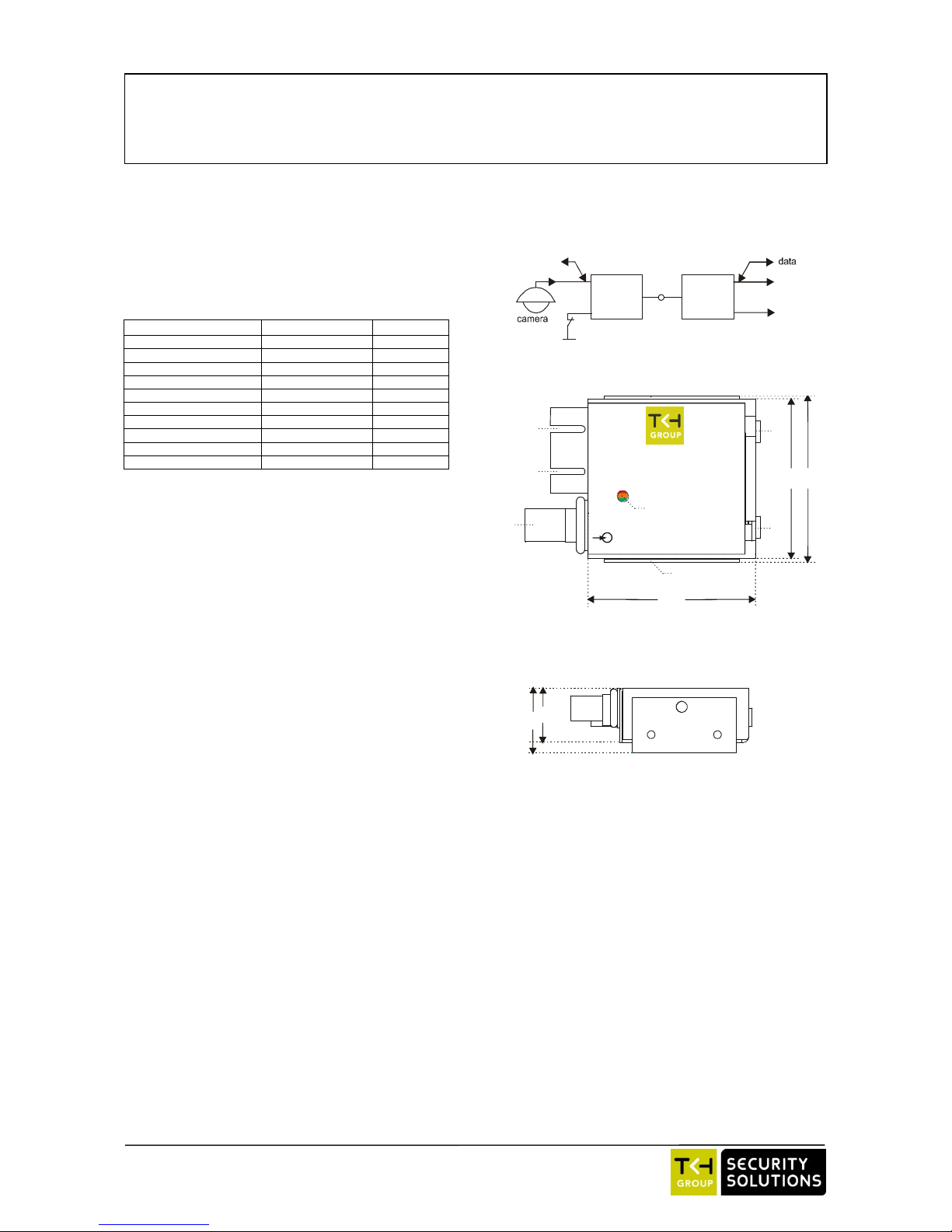
2. Indicators and connectors
Transmitters
The miniature stand-alone UTF transmitter has the
following parts, indications, and connectors (figure 2a):
1: TX: Primary optical fiber connection
2: RX (unmarked): Secondary optical fiber connec-
tion (not used in 4210 and 4250 models)
3: BNC 75 Ω connector: Composite video input
4: DC: shows SYNC: This indicator can show:
Green: Operational link
Red: Local synchronisation error
Yellow: Remote synchronisation error.
5: Mounting bracket
6: CC/GND: 2-Pin Combicon connector for alarm
contacts
7: DC 12-24 V / AC 24 V: 2-Pin power supply
connector (Combicon)
49,7
49,6
47,
5
TX
VIDEO IN
DC
GND
CC
DC 12-24V
AC 24V
Up-the-Fiber
™
D I G I T A L
1
2
3
5
6
7
5
4
24,5
20,5
Figure 2b. Miniature UTF transmitter (TX-MSA),
side view. Sizes in millimetres.
Figure 1. UTF general connection; data may come from camera
fiber
video
contact closure
UTF
TX
cc
UTF
RX
data
video
coax coax
Figure 2a. Indicators and connectors on the miniature
UTF transmitter (TX-MSA). Sizes in millimetres.
© Siqura 2017
Version 052706-2g
UTF 42xx BX(Bilinx) (MW10)
2
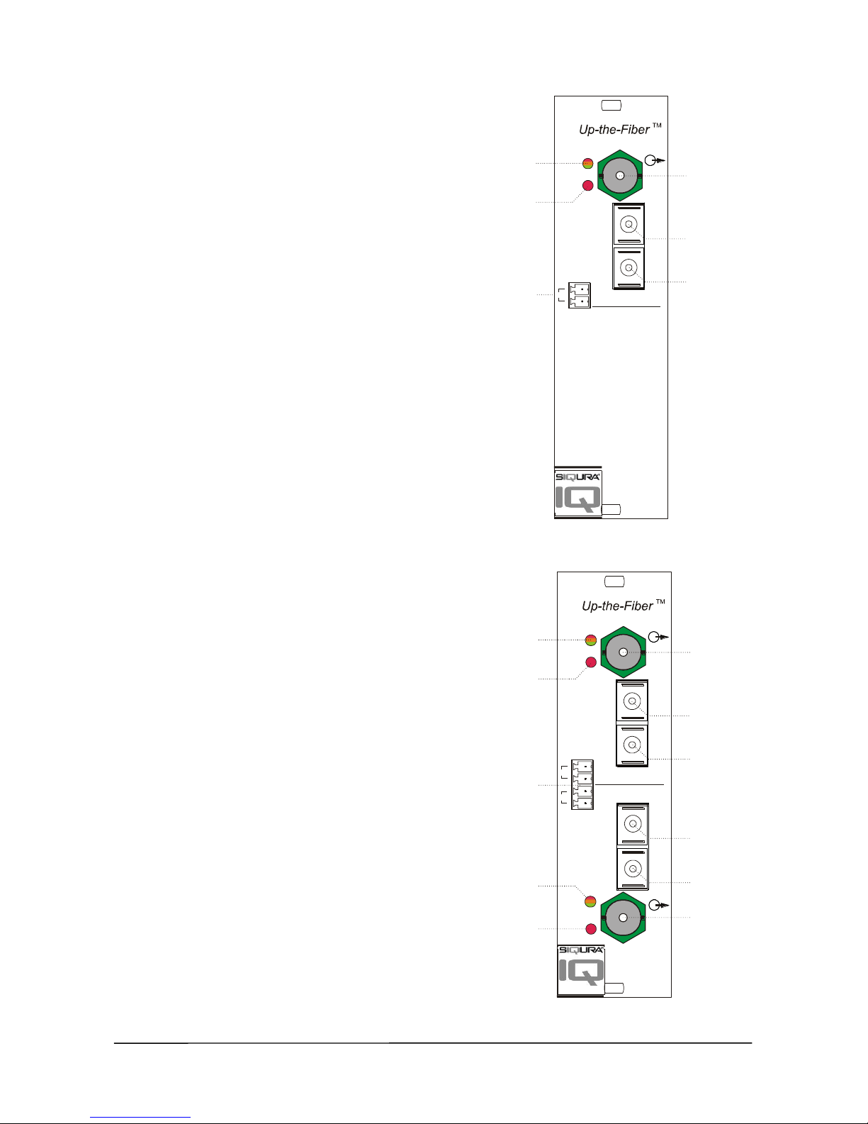
Receivers
The UTF Bilinx receivers (figures 3 and 4) have the
following indications and connectors:
1. SYNC: This LED can show:
Green: Operational link
Orange: Remote synchronisation error
Red: Local synchronisation error
2. NV: This LED can show:
Red: No video on in- or output
Off: Video signal present
3. Connector for potential-free alarm contacts:
RX model : 2-pin connector (channel CC1)
RX-2 model : 4-pin connector (channel CC1
and channel CC2)
4. BNC 75 Ω connector: Composite video output
5. TX: Connection for optical fiber
6. RX : Connection for optical fiber
In one-fiber units only TX is used.
3. Configuration and installation
! Note on powering of a UTF TX-MSA with 24 Vac
from the camera !
The miniature stand-alone transmitter can convert
24 Vac power through an internal full rectifier bridge;
the "-" of its internal DC voltage is connected to the
metal housing. If the camera uses the same Vac power
supply in parallel, but with a single-sided rectifier
circuit, the UTF power supply diodes may suffer, since
there always will be a connection between the housings
through the coax cable shielding. To prevent the
occurrence of such problems, proper measures must be
taken to separate the two loads of the 24 Vac supply;
this might be preferable in any case, as a precaution.
If in doubt, please contact your distributor.
Mounting
Before mounting the miniature transmitter, the
mounting bracket has to be installed in a suitable place.
After securing the bracket, the transmitter can be
clicked into it. Make sure the transmitter is positioned
and fixed correctly.
A stand-alone receiver can be easily installed; prevent
undue bending of cabling. In case more than one
receiver is needed, use TKH Security MC 10 or MC 11
cabinets.
Powering up a system
When powering up an appropriately connected system,
the "DC” indicator on the transmitter (if suitably
powered) should show green and the "SYNC" indicator
on the receiver should also light up green. If no video
signal is present, the corresponding "NV" indicator
shows red. DC and SYNC indicators on systems not
connected will light red.
Figure 3. Indications and connectors
on a UTF Bilinx RX receiver
Figure 4. Indications and connectors
on a UTF Bilinx RX-2 receiver
RX
VIDEO
RX
NV
CCI
SYNC
1
2
3
4
6
TX
5
RX-2
VIDEO
VIDEO
CH2
RX
RX
CHI
NV
NV
CCI
CC2
SYNC
1
2
3
2
4
6
6
4
SYNC
1
TX
5
5
TX
 Loading...