

Siqura TETRA 4210,TETRA 4250 User Manual
© Siqura 2017
Version 090902-1g
TETRA42x0TX&RX (MW10)
TETRA 42x0
Four Channel Digital Video Multiplexer with Two-Way Data
USER MANUAL
1. General description
TETRA 42x0 (4210 for multimode, and 4250 for singlemode) digital-optical multiplexer/demultiplexer systems
can transmit signals through four unidirectional,
independent composite video channels and one bidirectional data channel using one optical fiber per
system. Video and data/audio input signals are sampled
and digitised with 10-bit accuracy.
TETRA 42x0 TX unit receives input via the four BNC
connectors. It then converts and combines the four
channels of composite video with the data channel into
one digital data stream. This, in turn, is converted into an
optical signal, with a wavelength of 1310 nm. The
TETRA 42x0 TX also converts and decodes an incoming
1550 nm digital optical signal from the mating RX unit
that includes the data in the opposite (return) direction.
The TETRA 42x0 RX receives, converts and decodes
the video and data signals arriving through the optical
fiber via a 1310 nm optical carrier. It also converts and
serializes the incoming data signal and transmits this
information optically in the opposite direction towards
the complementary TX, using an optical wavelength of
1550 nm.
The composite video channels are digitally clamped after
being AC coupled at the inputs. The digital clamp is
compatible with NTSC and PAL sync timing. The video
channels are not compatible with non-video (NTSC and
PAL) signals.
The data channel I/O compatibility (RS-232, RS-422,
RS-485-4W, and RS-485-2W) and termination
configuration is selectable via an on board 10 position
dip-switch. See Data Configuration.
Front panel status LEDs indicate DC power OK, video
signal presence, local and remote link synchronisation.
TETRA 42x0 units are single-width (7TE) Eurocardsized modules and should be used in combination with
MC 11 or similar power supply cabinets.
Stand-alone models (/SA option, see supplementary
/SA-2 manual) need separate 12 Vdc power supplies.
A TKH Security PSA 12 DC-25 would be suitable.
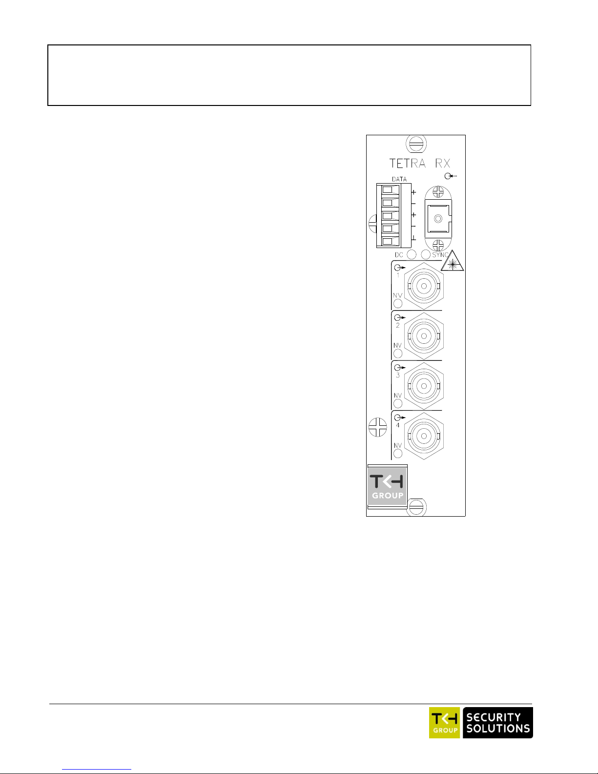
Figure 1. Tetra 42x0 RX Front Panel. TX panels look similar,
with video inputs instead of outputs. See Table 1.
2. Indications and connectors
TETRA 42x0 TX
o
(SC/UPC connector)
Optical video/data out, optical
data in
o
(BNC connector) 1-8
Composite video in
TETRA 42x0 RX
o
(SC/UPC connector)
Optical video/data in,
optical data out
o
(BNC connector) 1-8
Composite video out
TETRA 42x0 TX and RX
(2x)
Front panel screws
Status indicator LEDs
SYNC (red)
(orange)
(green)
No sync from optical in
or no internal sync
No sync from remote optical in
All sync OK
DC (green)
DC power OK
NV (red)
TX: no video in
RX: no video out
Table 1. TETRA 42x0 front panel features
Table 1 lists the front panel features of TETRA 42x0
modules (refer to figure 1). Connector pin assignments
are detailed in section 4.
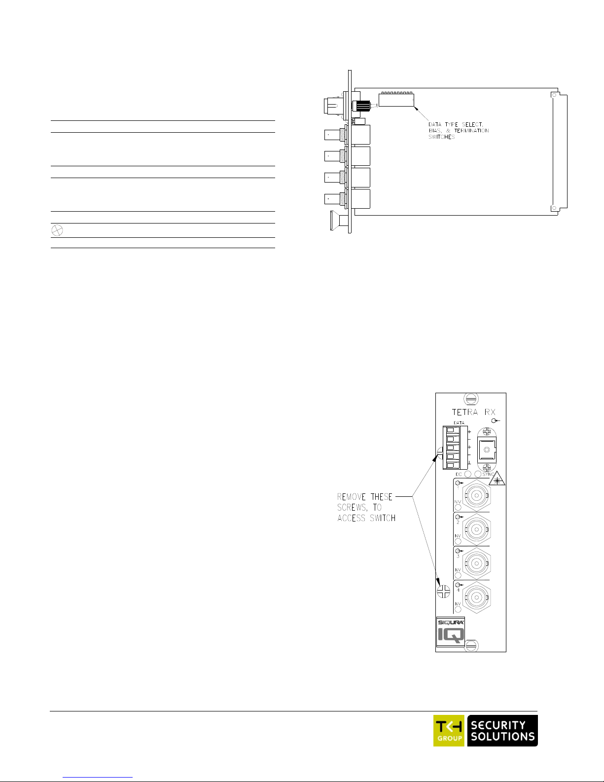
3. Configuration
To access the internal Data Type Select, Line Bias, and
Termination Dipswitch, remove the two screws on the
front panel as indicated in figure 3, and slide out the
circuit card assembly.
Figure 2: Location of Data Type Select, Line Bias, and
Termination Dipswitch
2
Figure 3. Access to internal configuration dipswitch
 Loading...