

Siqura SAFIX Series, SA-FIX24, SA-FIX115, SA-FIX230, SA-FIX24W Installation Manual
...
Document name: safixseries_v3-IM-EN.docx
Installation manual
SA FIX Series
316L Fixed camera station
2 of 7 | P a g e
Copyright © 2019 Siqura B.V.
All rights reserved.
SA FIX Series
Installation Manual v3 AIT55
Nothing from this publication may be copied, translated, reproduced, and/or published by means of
printing, photocopying, or by any other means without the prior written permission of Siqura.
Siqura reserves the right to modify specifications stated in this manual.
Brand names
Any brand names mentioned in this manual are registered trademarks of their respective owners.
Liability
Siqura accepts no liability for claims from third parties arising from improper use other than that
stated in this manual.
Although considerable care has been taken to ensure a correct and suitably comprehensive description
of all relevant product components, this manual may nonetheless contain errors and inaccuracies. We
invite you to offer your suggestions and comments by email via sales@siqura.com. Your feedback will
help us to further improve our documentation.
How to contact us
If you have any comments or queries concerning any aspect related to the product, do not hesitate
to contact:
Siqura B.V.
Meridiaan 32
2801 DA Gouda The Netherlands
General : +31 182 592 333
Fax : +31 182 592 123
E-mail : sales.nl@siqura.com
WWW : siqura.com
Note: To ensure proper operation, please read this manual thoroughly before using the
product and retain the information for future reference.

3 of 7 | P a g e
DESCRIPTION
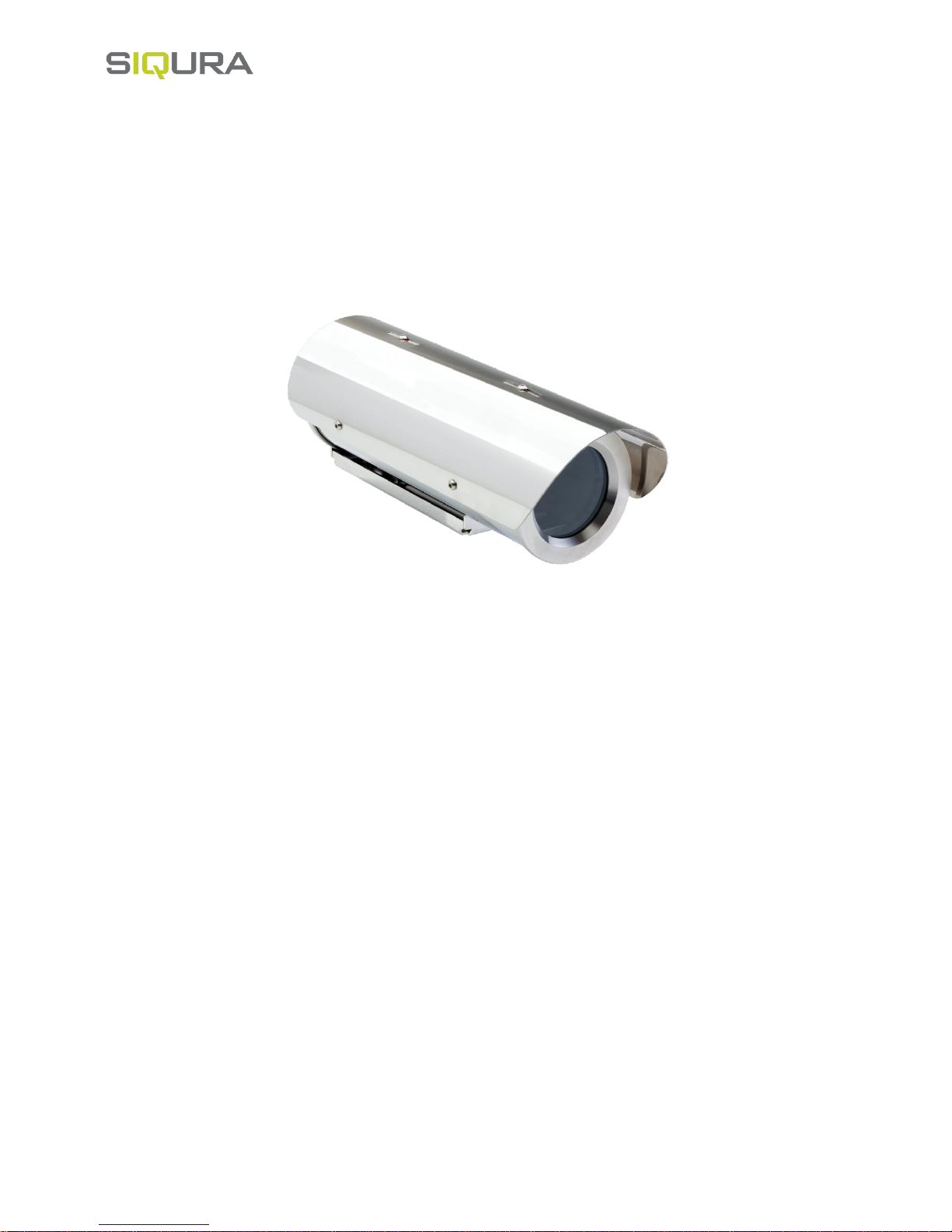
The SA-FIX W camera housing is a rugged corrosion proof camera housing designed for use in onshore, offshore, marine
and heavy industrial environments. The camera housing is constructed from electro-polished 316L stainless steel for
maximum corrosion protection and is fitted with an 316L sun-shield, a thermostatically controlled heater element, and a
integrated wiper. The housing is not sold separately, it is only available in combination with a Siqura daylight camera
module, such as the BC822v2H3-AS, and an interface (INT-RJ/SM/MM).
MODELS
SA-FIX24 Safe Area Fixed Camera 316L 24VAC
SA-FIX115 Safe Area Fixed Camera 316L 115VAC
SA-FIX230 Safe Area Fixed Camera 316L 230VAC
SA-FIX24W Safe Area Fixed Camera 316L 24VAC, Wiper
SA-FIX115W Safe Area Fixed Camera 316L 115VAC, Wiper
SA-FIX230W Safe Area Fixed Camera 316L 230VAC, Wiper
SA-FIX24T Safe Area Fixed Thermal Camera 316L 24VAC
SA-FIX115T Safe Area Fixed Thermal Camera 316L 115VAC
SA-FIX230T Safe Area Fixed Thermal Camera 316L 230VAC
INSTALLING THE CAMERA
Prior to installation and operation, carefully read all instructions the in this manual and heed all warnings.
Unpack this equipment and handle it carefully. If the package appears to be damaged, notify the shipper immediately.
Use the original packaging to transport the unit. Disconnect power supply before moving it. In case of returning the equipment, the original
packaging must be used.
Make sure that the installation surface can support at least four times the weight of the unit in normal operating conditions. In case of
excessive external stress (e.g. vibration, strong winds or impact), the equipment may need additional means of protection.
Proper stainless steel hardware should be carefully chosen to fasten the unit to the surfaces.
Use caution when lifting and assembling the unit. It is recommended that non-slip protective gloves be worn during installation. The unit
could bear sharp edges.
Trying to manually force the wiper will result in damaging the device and will void the warranty.
To maintain the IP rating of the unit, adequate cable glands must be used. The unit must be tightly closed when operating.
For security reasons, do not install the unit in the proximity of water containers and never push objects or pour liquids into the unit. The
unit can be safely used in damp environments or outdoors, as long as the connectors are properly sealed.
Video and data cables should not share the same conduit with supply voltage cables. Whenever EMC is an issue, adequately shielded
cables must be used.
Open only the covers pointed out in this installation manual. Other covers should be open only by the manufacturer.
This equipment has been designed to fit in harsh environments requiring little or no maintenance. Suggested inspection interval is 6
months, but extremely harsh environments may require more frequent inspection and maintenance checks. On each inspection check the
O-ring seals and the eventual window wiper blade integrity. Replace them if necessary.
Check cables, electrical connections and mounting hardware for integrity and tightness. Replace or tighten any damaged/loose part.
Operating temperature: -20° +55° C (-4° +131° F).
Before performing any operation, turn off the power. The installation of the unit can be performed only by qualified personnel in accordance
with the regulations in force. Do not connect the unit to a supply circuit unless the installation is completed.
Check carefully the supply voltage marked on the label. Incorrect Power Supply Voltage may damage the unit. Do not overload the terminal
connection, as it may cause a fire or electrical shock hazard.
An all-pole mains switch with an opening distance between the contacts at least 3 mm in each pole must be incorporated in the electrical
installation. The switch must be equipped with protection against the fault current towards the ground (differential) and the overcurrent
(magnetothermal, maximum 15A). It must be very quickly recognizable and readily accessible. A suitable blow fuse must also be installed
for protection.
For connection to the mains, use a multipolar cable having minimum 3x1,5 mm2 (15 AWG). The main cable must be at least protected by
an ordinary PVC sheath.
Fasten all the cables inside the housing with cables ties or other fixing means to avoid the electrical contact with surrounding parts in case
that terminal blocks screw off.
Electrical connections (such as plugs and cords) must be protected from potential hazardous environmental factors (e.g. foot traffic, hitting
objects).
Ensure that the unit case is properly earthed, connecting all the earth ground studs. Earth cable should be about 10mm longer than the
other cables on the connector, in such way that it won't be accidentally disconnected if the cable is stretched or pulled.
When leaving the unit unused for long periods, disconnect supply cables.
2
 Loading...