

Siqura S620 E User Manual

S620 E
Firmware Version 4.22
Dual H.264/MPEG-4 video encoder
User Manual

Note: To ensure proper operation, please read this manual thoroughly before using the
product and retain the information for future reference.
Copyright © 2017 Siqura B.V.
All rights reserved.
S620 E v4.22
User Manual v6 (120607-6)
AIT55
Nothing from this publication may be copied, translated, reproduced, and/or published by
means of printing, photocopying, or by any other means without the prior written permission
of Siqura.
Siqura reserves the right to modify specifications stated in this manual.
Brand names
Any brand names mentioned in this manual are registered trademarks of their respective
owners.
Liability
Siqura accepts no liability for claims from third parties arising from improper use other than
that stated in this manual.
Although considerable care has been taken to ensure a correct and suitably comprehensive
description of all relevant product components, this manual may nonetheless contain errors
and inaccuracies. We invite you to offer your suggestions and comments by email via
t.writing@tkhsecurity.com. Your feedback will help us to further improve our documentation.
How to contact us
If you have any comments or queries concerning any aspect related to the product, do not
hesitate to contact:
Siqura B.V.
Zuidelijk Halfrond 4
2801 DD Gouda
The Netherlands
General : +31 182 592 333
Fax : +31 182 592 123
E-mail : sales.nl@tkhsecurity.com
WWW : http://www.tkhsecurity.com
2

Contents
1 About this manual ..................................................................................... 8
2 Safety and compliance .............................................................................. 9
2.1 Safety ................................................................................................ 9
2.2 Compliance ......................................................................................... 11
3 Product overview ...................................................................................... 12
3.1 Features ............................................................................................. 12
3.2 Models ............................................................................................... 12
3.3 Description ......................................................................................... 13
3.4 Front panel ......................................................................................... 14
4 Install the unit .......................................................................................... 16
4.1 Power the unit ..................................................................................... 16
4.2 Connect cables .................................................................................... 16
4.3 Startup .............................................................................................. 17
4.4 Connector pin assignments ................................................................... 17
4.5 Update device definitions ...................................................................... 18
5 Connect the unit ........................................................................................ 19
5.1 Establish a network connection .............................................................. 19
5.2 Establish video and other signal connections ........................................... 21
5.2.1 Port numbers .................................................................................. 22
6 Interfaces ................................................................................................. 23
6.1 ONVIF ................................................................................................ 23
6.2 OSA ................................................................................................... 23
6.3 Web UI ............................................................................................... 23
6.4 MX/IP ................................................................................................ 24
6.5 SNMP ................................................................................................. 24
6.6 SAP ................................................................................................... 24
6.7 NTCIP ................................................................................................ 24
7 Stream media via RTSP ............................................................................. 26
7.1 RTSP and RTP ..................................................................................... 26
7.2 Transfer via UDP or TCP ....................................................................... 27
8 Access the webpages ................................................................................ 28
8.1 System requirements ........................................................................... 28
8.2 Connect via web browser ...................................................................... 28
8.3 Find the unit with Device Manager ......................................................... 29
8.4 Connect via UPnP ................................................................................ 30
8.5 Log on to the unit ................................................................................ 30
9 Navigate the webpages ............................................................................. 32
9.1 Menu ................................................................................................. 32
9.2 Access control ..................................................................................... 32
9.3 Webpage elements .............................................................................. 33
10 View live video via browser ....................................................................... 34
10.1 Activate Live View ................................................................................ 34
3

Contents
10.2 View live video .................................................................................... 35
10.3 Use your browser for PTZ control ........................................................... 36
11 Status ....................................................................................................... 38
11.1 View status information ........................................................................ 38
11.1.1 Stream states ................................................................................. 38
11.1.2 Edge recording ................................................................................ 39
11.2 View measurements data ...................................................................... 40
11.2.1 General, network, and stream measurements ...................................... 40
11.2.2 SD card size .................................................................................... 40
11.2.3 FTP Push ........................................................................................ 41
12 Network .................................................................................................... 42
12.1 Network settings ................................................................................. 42
12.2 Advanced ........................................................................................... 43
12.2.1 Services ......................................................................................... 43
12.2.2 Network ......................................................................................... 43
13 Video ......................................................................................................... 44
13.1 Video encoding overview ...................................................................... 44
13.2 General .............................................................................................. 45
13.2.1 Video Settings ................................................................................. 46
13.2.2 Encoder Priorities ............................................................................. 47
13.3 Encoder 1 ........................................................................................... 48
13.3.1 Encoder Settings ............................................................................. 49
13.3.2 Combinations of settings ................................................................... 51
13.3.3 Notes ............................................................................................. 51
13.3.4 Make a video connection ................................................................... 51
13.3.5 Advanced ....................................................................................... 53
13.3.5.1 Encoder ................................................................................... 53
13.3.5.2 Stream Manager ....................................................................... 55
13.3.5.3 Transmitter # ........................................................................... 56
13.3.5.4 RTSP Transmitter ...................................................................... 57
13.3.5.5 SAP Settings ............................................................................ 58
13.3.5.6 Meta data insertion ................................................................... 60
13.3.5.7 Notes ...................................................................................... 63
13.4 H.264 - 1 ........................................................................................... 65
13.4.1 Encoder Settings ............................................................................. 66
13.4.2 Constant Quality Mode configuration .................................................. 67
13.4.3 Profiles ........................................................................................... 68
13.4.4 Parameter value combinations ........................................................... 70
13.4.5 MX Transmitter Settings and making video connections ........................ 70
13.4.6 Advanced ....................................................................................... 70
13.4.6.1 Encoder ................................................................................... 71
13.4.6.2 Stream Manager, Transmitter #, RTSP Transmitter, and SAP .......... 73
13.5 H.264 - 2 ........................................................................................... 73
13.5.1 Edge recording ................................................................................ 73
13.6 Live View ............................................................................................ 74
13.6.1 (M)JPEG output ............................................................................... 74
13.6.2 Encoder Settings ............................................................................. 75
13.6.3 Advanced ....................................................................................... 75
13.7 OSD ................................................................................................... 76
13.7.1 OSD facilities .................................................................................. 76
13.7.2 Text Settings .................................................................................. 77
13.7.3 Text # ............................................................................................ 77
13.7.3.1 Advanced ................................................................................. 78
4

Contents
13.7.4 Graphics ......................................................................................... 79
13.7.4.1 Advanced ................................................................................. 80
13.8 VMD .................................................................................................. 81
13.8.1 VMD startup .................................................................................... 81
13.8.2 Configure detection parameters ......................................................... 82
13.8.3 Set the mask .................................................................................. 82
13.8.4 VMD detection window ..................................................................... 84
13.8.5 VMD alarm ...................................................................................... 84
13.8.6 Advanced ....................................................................................... 84
13.9 FTP Push ............................................................................................ 86
13.9.1 Post JPEG images ............................................................................ 87
13.9.2 General .......................................................................................... 87
13.9.3 FTP server ...................................................................................... 87
13.9.4 Event management .......................................................................... 88
13.9.5 Monitor and troubleshoot FTP Push ..................................................... 89
13.10 Image Monitor ..................................................................................... 90
13.10.1 Image quality check ......................................................................... 90
13.10.2 Enable the Image Monitor ................................................................. 90
13.10.3 Dial legend ..................................................................................... 92
13.10.4 Measurements configuration .............................................................. 94
13.10.5 Region of Interest (ROI) ................................................................... 95
13.11 Tamper Detect .................................................................................... 96
13.11.1 Camera movement and scene changes ............................................... 97
13.11.2 Enable Tamper Detect ...................................................................... 97
13.11.3 Reference images ............................................................................ 97
13.11.3.1 Create a reference image ........................................................... 97
13.11.3.2 Mask the ROI ........................................................................... 98
13.11.3.3 Compare images ....................................................................... 98
13.11.3.4 Delete a reference image ........................................................... 99
13.11.4 Position measurement ...................................................................... 100
13.11.5 Alarms ........................................................................................... 101
13.11.5.1 Alarm examples ........................................................................ 102
13.12 Privacy Mask ....................................................................................... 103
14 Audio ........................................................................................................ 104
14.1 Enable audio ....................................................................................... 104
14.1.1 Input Settings ................................................................................. 105
14.1.2 Output Settings ............................................................................... 105
14.2 Make audio connections ........................................................................ 106
14.2.1 MX Transmitter Settings ................................................................... 106
14.2.2 MX Receiver Settings ........................................................................ 107
14.3 Advanced ........................................................................................... 107
14.3.1 Audio Input ..................................................................................... 107
14.3.2 Audio Output ................................................................................... 108
14.3.3 Audio Encoder ................................................................................. 108
14.3.4 Audio Decoder ................................................................................. 108
14.3.5 Transmitter # ................................................................................. 109
14.3.6 Receiver 1 ...................................................................................... 110
14.3.7 RTSP Transmitter ............................................................................. 111
14.3.8 SAP Settings ................................................................................... 112
15 Data RS-422/485 ...................................................................................... 114
15.1 General Settings .................................................................................. 114
15.2 UART Settings ..................................................................................... 115
15.3 Make data connections ......................................................................... 115
15.4 TCP Server Settings ............................................................................. 116
5

Contents
15.5 Advanced ........................................................................................... 116
15.5.1 RS-4xx Settings .............................................................................. 116
15.5.2 Transmitter # ................................................................................. 118
15.5.3 Receiver 1 ...................................................................................... 118
16 Data RS-232 .............................................................................................. 120
16.1 Configure RS-232 settings .................................................................... 120
17 CC Streams ............................................................................................... 121
17.1 CC channels, CC status, and alarms ....................................................... 121
17.2 Input # Settings .................................................................................. 122
17.3 Make contact closure connections .......................................................... 122
17.4 Advanced ........................................................................................... 123
17.4.1 Transmitter # ................................................................................. 123
17.4.2 Receiver 1 ...................................................................................... 123
18 PTZ ........................................................................................................... 125
18.1 Enable PTZ control ............................................................................... 125
18.2 Upload/Remove PTZ drivers .................................................................. 126
18.3 Data Settings ...................................................................................... 126
19 Security ..................................................................................................... 127
19.1 HTTPS ................................................................................................ 127
19.2 Certificate/Request information ............................................................. 128
19.3 CA-Issued certificate ............................................................................ 128
19.4 Self-signed certificate ........................................................................... 129
19.5 Open a secure connection ..................................................................... 129
20 Edge recording .......................................................................................... 130
20.1 Edge recording basics ........................................................................... 130
20.2 Monitoring .......................................................................................... 131
20.3 Recording ........................................................................................... 131
20.4 Clips .................................................................................................. 131
20.5 SD card .............................................................................................. 132
21 Event management ................................................................................... 133
21.1 Associate events with output facilities ..................................................... 133
21.1.1 CC Output # ................................................................................... 133
21.1.2 CC Stream # ................................................................................... 134
21.1.3 FTP Push ........................................................................................ 134
21.1.4 Recorder ........................................................................................ 135
22 Device management .................................................................................. 136
22.1 General .............................................................................................. 136
22.1.1 Identification ................................................................................... 136
22.1.2 Device Name ................................................................................... 137
22.1.3 Advanced ....................................................................................... 137
22.1.3.1 Alarm Settings .......................................................................... 137
22.1.3.2 LED control .............................................................................. 137
22.2 Logging .............................................................................................. 138
22.2.1 Log file ........................................................................................... 138
22.2.2 Syslog settings ................................................................................ 138
22.3 SNMP ................................................................................................. 138
22.3.1 SNMP System Information ................................................................ 139
22.3.2 SNMP Communities .......................................................................... 139
22.3.3 SNMP Agent .................................................................................... 139
6

Contents
22.3.4 SNMP Traps .................................................................................... 139
22.3.5 Polling ............................................................................................ 139
22.4 MX ..................................................................................................... 140
22.4.1 MX/IP ............................................................................................. 140
22.4.2 MX Notifications ............................................................................... 140
22.5 Auto Discovery .................................................................................... 141
22.5.1 Advertise the S620 E ........................................................................ 141
22.5.1.1 Note ........................................................................................ 141
22.6 ONVIF ................................................................................................ 142
22.6.1 Note .............................................................................................. 142
22.7 FTP/Telnet .......................................................................................... 142
22.8 Firmware ............................................................................................ 143
22.8.1 Firmware images ............................................................................. 143
22.8.2 Current Version ............................................................................... 143
22.8.3 Upgrade ......................................................................................... 144
22.8.4 Troubleshoot upgrade issues ............................................................. 144
22.8.5 Advanced ....................................................................................... 145
22.9 Backup/Restore ................................................................................... 146
22.9.1 Backup ........................................................................................... 146
22.9.2 Restore .......................................................................................... 146
22.10 Reboot ............................................................................................... 146
23 User Management ..................................................................................... 148
23.1 Web Access ........................................................................................ 148
23.1.1 Access control ................................................................................. 148
23.1.2 Manage user accounts ...................................................................... 148
23.2 Linux ................................................................................................. 149
24 Date and Time ........................................................................................... 151
24.1 Date and time ..................................................................................... 151
24.2 SNTP Settings ..................................................................................... 152
24.3 Advanced ........................................................................................... 153
25 Multicasting .............................................................................................. 154
25.1 Multicast ............................................................................................ 154
25.2 Multi-unicast ....................................................................................... 155
Appendix: Enable JavaScript ..................................................................... 156
Appendix: Enable UPnP in Windows .......................................................... 157
Appendix: Install a video player ................................................................ 158
Download video player software ............................................................ 158
Install QuickTime ................................................................................. 158
Install VLC .......................................................................................... 158
Appendix: NTCIP Configuration ................................................................. 160
Supported conformance groups ............................................................. 160
Configuration .................................................................................. 160
CCTV configuration .......................................................................... 161
Motion control ................................................................................. 161
SNMP MIB .......................................................................................... 162
Appendix: Technical specifications ............................................................ 163
7

1 About this manual
What this manual covers
This manual applies to the S620 E v4.22, TKH Security's H.264/MPEG-4 video server.
It explains:
● How to install the unit
● How to establish connections
● How to communicate with the unit
● How to configure the device settings
● How to operate the unit
Who should read this manual
This manual is intended for installers and users of the S620 E.
What you should already know
To be able to install and use the S620 E properly, you should have adequate knowledge and
skills in the following fields.
● Installing electronic devices
● Ethernet network technologies and Internet Protocol (IP)
● Windows environments
● Web browsers
● Video, audio, data, and contact closure transmissions
● Video compression methods
Before you start
We advise you to read and observe all instructions and warnings in this manual before you
continue. Keep this manual with the original bill of sale for future reference and warranty
service. When you unpack your product, check for missing or damaged items. If any item is
missing, or if damage is evident, do not install or operate this product. Contact your supplier
for assistance.
Why specifications may change
We are committed to delivering high-quality products and services. The information given in
this manual was current when published. As we continuously seek to improve our products
and user experience, all features and specifications are subject to change without notice.
We like to hear from you!
Customer satisfaction is our first priority. We welcome and value your opinion about our
products and services. Should you detect errors or inaccuracies in this manual, we would be
grateful if you would inform us. We invite you to offer your suggestions and comments via
t.writing@tkhsecurity.com. Your feedback helps us to further improve our documentation.
Acknowledgement
This product uses the open-source Free Type font-rendering library. The Open Source
Libraries and Licenses document, available at www.tkhsecurity.com/support-files, gives a
complete overview of open source libraries used by our video encoders and IP cameras.
8

2 Safety and compliance
This chapter gives the S620 E safety instructions and compliance information.
In This Chapter
2.1 Safety................................................................................................................... 9
2.2 Compliance.......................................................................................................... 11
2.1 Safety
The safety information contained in this section, and on other pages of this manual, must be
observed whenever this unit is operated, serviced, or repaired. Failure to comply with any
precaution, warning, or instruction noted in the manual is in violation of the standards of
design, manufacture, and intended use of the module. Siqura assumes no liability for the
customer's failure to comply with any of these safety requirements.
Trained personnel
Installation, adjustment, maintenance, and repair of this equipment are to be performed by
trained personnel aware of the hazards involved. For correct and safe use of the equipment
and in order to keep the equipment in a safe condition, it is essential that both operating and
servicing personnel follow standard safety procedures in addition to the safety precautions
and warnings specified in this manual, and that this unit be installed in locations accessible to
trained service personnel only.
Safety requirements
The equipment described in this manual has been designed and tested according to the
UL/IEC/EN 60950-1 safety requirements. For compliance information, see the EU
Declaration of Conformity, which is available for download at www.tkhsecurity.com/supportfiles.
Warning: If there is any doubt regarding the safety of the equipment, do not put it into
operation.
This might be the case when the equipment shows physical damage or is stressed beyond
tolerable limits (for example, during storage and transportation).
Important: Before opening the equipment, disconnect it from all power sources.
The equipment must be powered by a SELV1 power supply. This is equivalent to a Limited
Power source (LPS, see UL/IEC/EN 60950-1 clause 2.5) or a "NEC Class 2" power supply.
When this module is operated in extremely elevated temperature conditions, it is possible for
internal and external metal surfaces to become extremely hot.
1. SELV: conforming to IEC 60950-1, <60 Vdc output, output voltage galvanically isolated
from mains. All power supplies or power supply cabinets available from TKH Security comply
with these SELV requirements.
9

Safety and compliance
Power source and temperature ratings
Verify that the power source is appropriate before you plug in and operate the unit. Use the
unit under conditions where the temperature remains within the range given in the Technical
Specifications of this product. You can download the S620 E datasheet at
www.tkhsecurity.com/support-files.
Optical safety
The following optical safety information applies to S620 E models with SFP interface.
This product complies with 21 CFR 1040.10 and 1040.11 except for deviations pursuant to
Laser Notice No. 50, dated June 24, 2007. This optical equipment contains Class 1M lasers or
LEDs and has been designed and tested to meet IEC 60825-1:1993+A1+A2 and IEC
60825-2:2004 safety class 1M requirements.
Warning: Optical equipment presents potential hazards to testing and servicing personnel,
owing to high levels of optical radiation.
When using magnifying optical instruments, avoid looking directly into the output of an
operating transmitter or into the end of a fiber connected to an operating transmitter, or there
will be a risk of permanent eye damage. Precautions should be taken to prevent exposure to
optical radiation when the unit is removed from its enclosure or when the fiber is disconnected
from the unit. The optical radiation is invisible to the eye.
Use of controls or adjustments or procedures other than those specified herein may result in
hazardous radiation exposure.
The installer is responsible for ensuring that the label depicted below (background: yellow;
border and text: black) is present in the restricted locations where this equipment is installed.
EMC
Warning: Operation of this equipment in a residential environment could cause radio
interference.
This device has been tested and found to meet the CE regulations relating to EMC and
complies with the limits for a Class A device, pursuant to Part 15 of the FCC rules. Operation
is subject to the following two conditions: (1) This device may not cause harmful interference,
and (2) This device must accept any interference received, including interference that may
cause undesired operation. These limits are designed to provide reasonable protection against
interference to radio communications in any installation. The equipment generates, uses, and
can radiate radio frequency energy; improper use or special circumstances may cause
interference to other equipment or a performance decrease due to interference radiated by
other equipment. In such cases, the user will have to take appropriate measures to reduce
such interactions between this and other equipment.
Note that the warning above does not apply to TKH Security products which comply with the
limits for a Class B device. For product-specific details, refer to the EU Declaration of
Conformity.
Any interruption of the shielding inside or outside the equipment could make the equipment
more prone to fail EMC requirements.
10

Safety and compliance
To ensure EMC compliance of the equipment, use shielded cables for all signal cables including
Ethernet, such as CAT5E SF/UTP or better, as defined in ISO IEC 11801. For power cables,
unshielded three wire cable (2p + PE) is acceptable Ensure that all electrically connected
components are carefully earthed and protected against surges (high voltage transients
caused by switching or lightning).
ESD
Electrostatic discharge (ESD) can damage or destroy electronic components. Proper
precautions should be taken against ESD when opening the equipment.
Care and maintenance
The unit will normally need no maintenance. To keep it operating reliably:
● Prevent dust from collecting on the unit.
● Do not expose the equipment to moisture.
RoHS
Global concerns over the health and environmental risks associated with the
use of certain environmentally-sensitive materials in electronic products have
led the European Union (EU) to enact the Directive on the Restriction of the
use of certain Hazardous Substances (RoHS) (2011/65/EU). TKH Security
offers products that comply with the EU’s RoHS Directive.
Product disposal
The unit contains valuable materials which qualify for recycling. In the
interest of protecting the natural environment, properly recycling the unit at
the end of its service life is imperative.
When processing the printed circuit board, dismantling the lithium battery
calls for special attention. This kind of battery, a button cell type, contains so
little lithium, that it will never be classified as reactive hazardous waste. It is
safe for normal disposal, as required for batteries by your local authority.
2.2 Compliance
The EU Declaration of Conformity for this product is available for download at
www.tkhsecurity.com/support-files.
11

3 Product overview
This chapter introduces the S620 E and its features.
In This Chapter
3.1 Features.............................................................................................................. 12
3.2 Models.................................................................................................................12
3.3 Description...........................................................................................................13
3.4 Front panel.......................................................................................................... 14
3.1 Features
S620 E
● Cost-effective dual H.264 video encoder
● 2x D1 at 30fps H.264 + 2x MPEG4/MJPEG
● Edge recording
● ONVIF Profile S
● Open Streaming Architecture
● Fiber and Ethernet over Coax (EoC) option
● Motion Adaptive Deinterlacing (M.A.D.™)
● Video motion detection
● Camera health check
● Tamper detection
● Duplex serial data and stereo audio
3.2 Models
The S620 E series includes the following models.
S620 E H.264/MPEG-4 video encoder with edge recording
S620 E -SFP Model with empty SFP slot
S620 E /SA Stand-alone version of rack-mount models
Rack-mount S620 E units are designed to be slotted into MC 10 or MC 11 power supply
cabinets. Front panel LEDs indicate network status, stream status (sync), and DC power. All
models have backup battery power for their clocks.
12

Product overview
3.3 Description
The S620 E combines H.264 video encoding with MPEG-4 or MJPEG. It offers an open solution
for IP video CCTV applications. The video server features dual-streaming H.264 with dualstreaming MPEG-4 or MJPEG, low bandwidth, low latency, edge recording, and interoperability
with most other systems.
Quad streaming
The S620 E is capable of streaming 2x H.264 at full frame rate. It can also stream 2x MPEG-4
or MJPEG simultaneously. Each stream is optimised for its purpose: high-quality H.264 for live
viewing, low-bandwidth MPEG-4 for storage, or easy-to-decode MJPEG for web applications
and remote devices.
Picture enhancement
Almost every analogue camera offers an interlaced signal (PAL or NTSC). On digital computer
monitors, this causes severe artefacts, such as comb edges on moving objects. To remove
these artefacts the video signal has to be deinterlaced. This can be done in the monitor, but
also at the beginning – at the encoder side. The S620 E is fitted with a motion adaptive
deinterlacer (M.A.D.). TKH Security's M.A.D removes the interlacing artefacts on the moving
objects only to preserve the vertical resolution of the image. In addition, the deinterlaced
image is much easier to encode, saving bits for streaming and storage.
Edge recording
The S620 E offers edge recording when the connection with the NVR is lost. The recorded
images are available as AVI and can easily be downloaded from the device. The recordings are
stored on a single µSDHC card with a maximum capacity of 32 GB.
ONVIF and Open Streaming Architecture (OSA)
The S620 E supports both the international ONVIF standard and TKH Security OSA for remote
control, configuration, video switching, and streaming. The S620 E has been approved for
ONVIF Profile S for streaming, PTZ, and I/O. OSA is a comprehensive HTTP RTSP based API,
which gives access (next to ONVIF) to all controls and makes full integration easy.
Image quality monitor and tampering alarm
When the image from the camera becomes too poor, an image quality alert is raised. The
built-in Image Quality Monitor continuously monitors the camera image on contrast, exposure,
sharpness, and noise. In addition, the built-in Tamper Detector monitors changes in the
camera’s position or field of view. The instant a camera’s position is changed a tamper detect
alert is raised.
Audio, data, and I/O contacts
By combining audio, programmable I/O contacts, and data with streaming video, the S620 E
provides all the interfaces necessary for any IP CCTV application. On the encoder module, you
will find two bidirectional audio channels (lip-synchronised), two digital inputs and outputs,
and two serial data ports (RS-232 and RS-422/482). The RS-422/485 data port is combined
with a built-in PTZ controller supporting a number of PTZ protocols.
Fiber and EoC options
The S620 E is available with an optional, pluggable SFP slot. This offers unparalleled flexibility
in connectivity. With fiber SFPs you can connect over multimode or single-mode optical fiber
cable and cover distances from 100 m to 120 km or more. To connect over (existing) coax,
you can use TKH Security's ECO-plug for Ethernet over Coax.
13

Product overview
FTP push
Upon an event, the S620 E can push a JPG image to one or two FTP servers. The event can be
triggered externally by VMD, the Image Monitor, or Tamper Detect. The S620 E can also
periodically upload images to the remote server(s).
Web interface
Configuration, management, and live viewing are simplified by the access-controlled web
interface. Full in-band control is available through Device Manager and the HTTP API. The
S620 E is field-upgradeable.
3.4 Front panel
Features and indications
The front panel of the S620 E has the following features.
14

Product overview
S620 E
VIDEO
A1, CC1 RJ-45 socket audio 1, contact closure
A2, CC2 RJ-45 socket audio 2, contact closure
D1, D2 RJ-45 socket RS-485/422, RS-232
SD micro SD slot used for micro SD card
Status indicator LEDs
*DC green DC power OK; blinks on
*NV red no video on input
*SYNC off all streams disabled
*D1 green/red RS-4xx 0/1 data input
*D2 green/off RS-232 0/1 data input
Ethernet
socket LEDs
BNC connector video input
RJ-45 socket
or SFP
green all enabled streams OK
red a transmitted stream
yellow a received stream fails
red/yellow
blink
green/yellow Green on/off: 100/10
Ethernet I/O, electrical
or fiber
1
2
identification and errors
fails
at least one transmitted
and at least one received
stream fail
Mbit
Yellow on/blink: link OK,
active
Yellow off/flash: link
down, TX attempt
S620 E front panel features and indications
Pin assignments are given in section Connector Pin Assignments.
15

4 Install the unit
This chapter describes how to install your S620 E unit and connect power, network, and signal
cables.
In This Chapter
4.1 Power the unit...................................................................................................... 16
4.2 Connect cables..................................................................................................... 16
4.3 Startup................................................................................................................17
4.4 Connector pin assignments.....................................................................................17
4.5 Update device definitions....................................................................................... 18
4.1 Power the unit
To power a rack-mount unit
1 Insert the S620 E into an MC 10 or MC 11 power supply cabinet.
2 Plug the cabinet power cord into a grounded mains socket.
To power a stand-alone unit
A stand-alone (/SA) S620 E requires an external power supply adapter (12 Vdc).
1 Connect the power adapter to the power connector on the metal SA housing.
2 Plug the power adapter into a grounded mains socket.
4.2 Connect cables
Use the appropriate connectors on the S620 E front panel to connect the network and signal
cables.
To connect the S620 E to your 100/10Mbit IP/Ethernet network
● Plug the network cable into the RJ-45 Ethernet socket on the front panel.
Important: Use appropriate cabling (Cat 5 or Cat 6) for network links.
To connect a video source
● Connect the coaxial cable from your video source (a camera, for example) to the video
input BNC connector on the front panel.
To connect audio, data, and/or contact closure sources/destinations
● Plug the cables carrying audio, data, and/or contact closure signals into the corresponding
RJ-45 sockets on the S620 E front panel.
16
Install the unit
Important: Through-connecting the signal ground lines of RS-data interfaces is mandatory,
as is proper grounding. See also the section on pin assignments later in this chapter.
4.3 Startup
After startup, the DC LED will light and the network indicator lights go through an on/off
sequence.
The power DC LED should always be lit. The link and No Video lights eventually glow upon
establishing of a good network link and the absence of an input video signal, respectively.
The sync LED displays as described in the Front Panel section.
Important: Before you can make any signal connection, you must assign at least a valid IP
address (the unit's identity for the network) and a subnet mask to the unit. The Connect the
unit chapter explains how to do this.
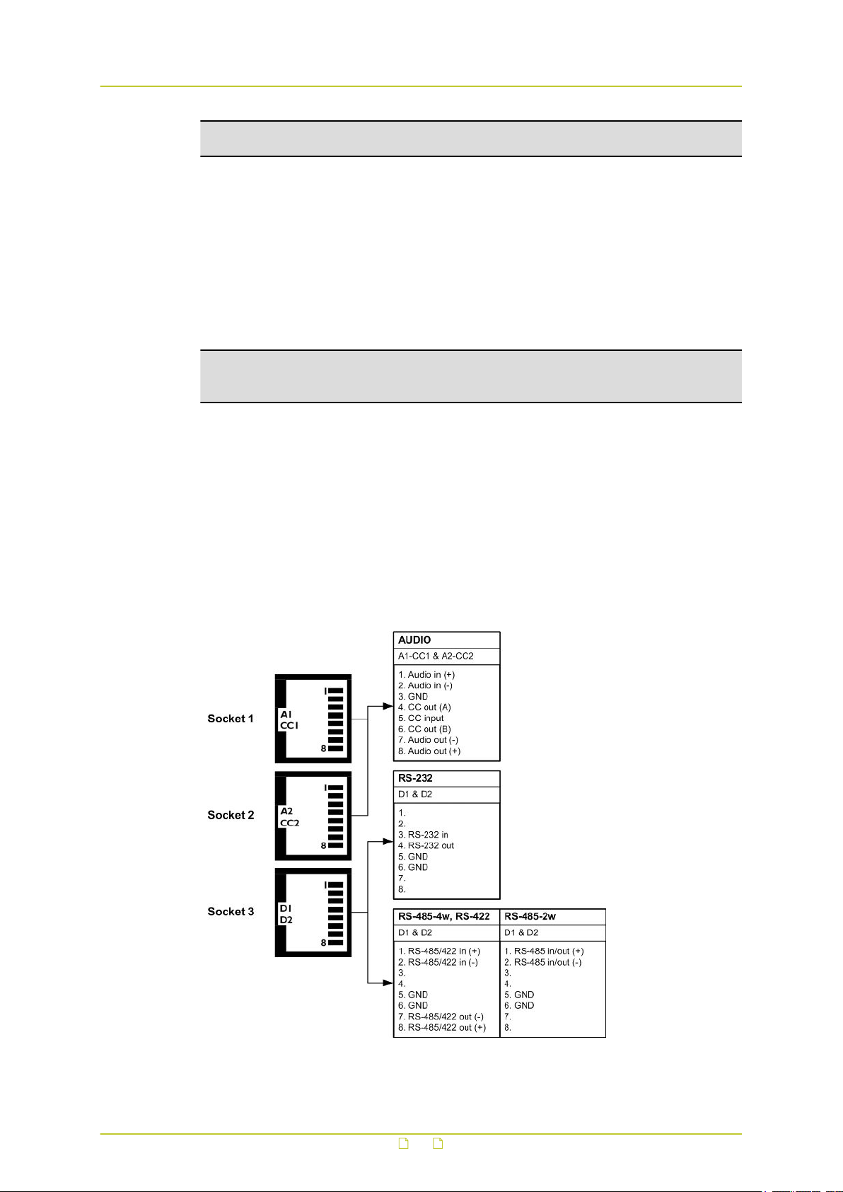
4.4 Connector pin assignments
Modular socket pin assignments
The modular socket pin assignments are such that similar sockets of different modules may be
connected back to back with reversed cable (RS-232 interfaces excepted). See the figure
below for the socket pin numbering convention used. For 2-wire RS-485 links, I/O is through
pins 1 and 2 of socket 3.
Pin assignments of the three modular sockets. For 2-wire RS-485 use pins 1 and 2 of socket 3.
17

Install the unit
Note: Polarity indications for RS-422/485 are based on a convention used by BT, which may
conflict with other implementations. Pelco systems, for example, use an implementation for
which you have to connect TKH Security (+) to Pelco (-) and vice versa.
Ethernet connector pin assignment
Ethernet connector socket pinning
4.5 Update device definitions
If the S620 E is not supported by the TKH Security application software on your host PC you
can download EMX updates and MX Plug-in updates at www.tkhsecurity.com/support-files.
Install the EMX update first if you are performing both update types.
Note: There is no need to install these updates if you do not use MX applications.
● EMX updates
Install the EMX update. The Embedded MX network driver will be updated with the latest
changes.
● MX Plug-in updates
The updater will update the shared copy of device definitions used by Ethernet-based MX
applications. An existing installation of the SNM Configuration and Service Tool will also be
updated.
18

5 Connect the unit
With your S620 E installed, the next step is to establish an IP connection and set up video and
(if applicable) other signal links. This chapter describes how you can change the factory-set IP
address and subnet mask of the S620 E to make them compatible with the network segment
in which the unit will be used. It also discusses how to configure signal streaming.
In This Chapter
5.1 Establish a network connection............................................................................... 19
5.2 Establish video and other signal connections.............................................................21
5.1 Establish a network connection
The webpages of the S620 E provide a convenient way of accessing its settings. You can log
on to the web interface of the S620 E from a PC which is on the same subnet as the unit.
Follow the steps below to open communication with the S620 E and configure its network
settings.
Step 1: Set the network adapter of the PC to the factory-set subnet of the S620 E
and then connect the two devices to the network.
Step 2: Access the unit from a web browser or other tool installed on the PC.
Step 3: Set the IP address and subnet mask of the S620 E to the subnet that it is
going to be used in and reboot the unit.
To address the unit from the same PC again, configure the network adapter of the PC once
more to assign the PC to the same subnet as the unit.
The factory-set IP address of the S620 E is in the 10.x.x.x range. You will find it printed on a
sticker on the unit.
S620 E product sticker
Note: This is the address the unit reverts to if you issue a "Reset to factory settings; incl.
network settings" command and reboot the unit (see chapter Device Management).
19
Connect the unit
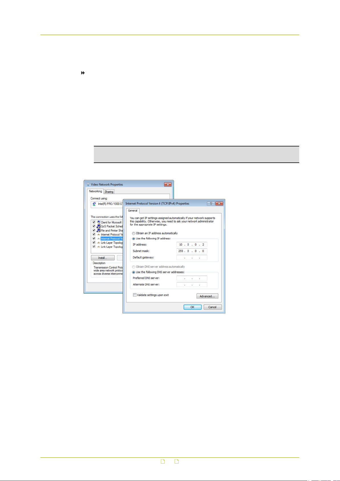
Step 1: Set the PC to the factory-set subnet of the unit
To configure the network adapter on the PC
1 In Control Panel, open Network and Sharing Center.
2 Select the connection to be configured, and then click Properties.
3 On the items list, select Internet Protocol Version 4 (TCP/IPv4).
4 Click Properties.
5 In the Internet Protocol Version 4 (TCP/IPv4) Properties dialog box, click Use the
following IP address.
6 Enter an IP address which assigns your PC to the same subnet as the S620 E - that is,
within the 10.x.x.x range. Use 255.0.0.0 as a subnet mask.
Important: To prevent conflicts, be sure to choose a unique IP address. No two
devices on a network can have the same IP address.
7 To apply the new settings, click OK.
Setting the IP settings of the PC to the factory-set IP settings of the unit
At this point, connect your PC to the S620 E. You can connect them directly using a crossover
cable, or connect both to a switch.
Step 2: Access the unit
Using a standard web browser you can now log on to the web server of the S620 E.
Step 3: Change the network settings of the unit
The Network page enables you to make the network addressing of the unit compatible with
the network it will be added to. You can set a fixed IP address or have the IP address assigned
by a DHCP server. In the latter case, open the Advanced Settings and enable DHCP. Do not
forget to save and reboot the unit after changing the settings.
20

Connect the unit
5.2 Establish video and other signal connections
Connection methods
With the IP connection established, video and other signal connections can be made. The
easiest way to connect with video and audio is by using RTSP or SAP. For more information,
see the Interfaces chapter.
An alternative, convenient method to establish video, audio, data, and contact closure (I/O
contacts) connections is to use the webpages of the S620 E. For detailed information, see the
chapters which describe these pages.
Separate application software, such as MX Configuration Tool, can be used as well.
Streams and connectors
Each signal stream transmitted and received by the S620 E (see the figure below) can be
conceived of as using virtual connectors (transmitters and receivers) on the network side.
Each of the virtual connectors has a name. Through the internal webpages, the receivers can
be assigned a port number which must be used only once for that particular device.
Depending on context, the assignment is automatic or manual. Note that port numbers must
be even.
Link facilities of the S620 E.
All arrows represent separate and independent connections over Ethernet.
The abbreviations ‘tx’ and rx’ refer to the network side of the module.
- tx: the stream is transmitted to the network
- rx: the stream is received from the network
21

Connect the unit
General procedure for making links
In both connection methods mentioned above, perform the following steps to make a unicast
one-way link (video, audio, data, contact closure) from source to destination.
● In the transmitter, specify a destination IP address and a destination port number.
● In a compatible receiver, specify the transmitter IP address (source) and the local input
port number (= the destination port number mentioned above).
● Do not forget to enable both the transmitter and the receiver.
It is possible for external software to configure a stream, for instance a video stream or a
contact closure stream to transmit a contact closure alarm. In such cases, port numbers are
assigned automatically from a range of unused values.
For more information on port number assignment, see Port Numbers.
5.2.1 Port numbers
A valid UDP port number in a TKH Security A-, C-, and S-series system is an unsigned 16-bit
integer between 1024 and 65536. Generally, you do not need to select other than the default
receiver port numbers as given in the MIB (Management Information Base). If you want to
change these receiver port numbers for some reason, use even numbers. A given receiver
port number N is associated with the port number N+1, through which control information is
returned to the source.
Eligible port numbers in general are within the range indicated above, with some exceptions.
Those within the 3000-10000 range are reserved and/or hard-coded, or may become
reserved, so only 10000-65535 are generally safe. Default port numbers (used by receivers)
are shown in the following table.
General Example
Video 50xxx Video 50010
Audio 51xxx Audio 51010
Data 52xxx Data 1 52010 (RS-4xx)
Data 2 52020 (RS-232)
CC 53xxx CC 1 53010
CC 2 53020
Default port numbers
MX applications using automatic port number allocation may use 55000 and up.
22

6 Interfaces
A variety of methods can be employed to communicate with the S620 E. This chapter outlines
the interfaces you can use to control the unit and manage the media streams it is handling.
In This Chapter
6.1 ONVIF................................................................................................................. 23
6.2 OSA.................................................................................................................... 23
6.3 Web UI................................................................................................................23
6.4 MX/IP..................................................................................................................24
6.5 SNMP.................................................................................................................. 24
6.6 SAP.....................................................................................................................24
6.7 NTCIP..................................................................................................................24
6.1 ONVIF
The Open Network Video Interface Forum (ONVIF) is an open industry forum for the
development of a global standard for the interface of IP-based physical security products.
ONVIF is committed to the adoption of IP in the security market. The ONVIF specification
ensures interoperability between products regardless of manufacturer. It defines a common
protocol for the exchange of information between network video devices including automatic
device discovery, video streaming and intelligence metadata. The S620 E fully supports
ONVIF. It has been tested to support ONVIF Profile S.
6.2 OSA
TKH Security's Open Streaming Architecture (OSA) consists of a standard set of open
communication protocols to govern media streaming via RTSP and equipment management
via HTTP. OSA enables easy integration of the S620 E with third-party products. The protocol
consists mainly of different CGI (Common Gateway Interface) program calls for listing and
configuring parameters. A detailed description of the HTTP API is given in the SPI specification
which can be downloaded at www.tkhsecurity.com/support-files.
6.3 Web UI
Using the S620 E's web server is the most straightforward way to access the unit. The
webpages enable you to configure the settings of the S620 E and view live video images from
a standard web browser.
23

Interfaces
6.4 MX/IP
MX/IP is a proprietary TKH Security protocol which gives direct access to the settings of the
S620 E. Using special MX software, such as MX Configuration Tool, S620 E settings can be
read from and written to the Management Information Base (MIB), a list of variables stored
inside the unit. Offering full control of the S620 E, the MIB enables you to remotely configure
device settings and manage media streams. Additional MX viewing and control software offers
real-time monitoring of video streams and playback of recorded images. For more information
about MX/IP, the MIB, and the EMX network service, refer to the manuals which document the
MX SDK and the MX applications.
Note: If you prefer using open standards, you can disable the MX/IP protocol. This is done
on the MX tab of the Device Management page. Be aware that doing so prevents you from
upgrading the S620 E firmware through MX Firmware Upgrade Tool.
6.5 SNMP
The Simple Network Management Protocol (SNMP), part of the internet protocol suite, can be
used to monitor network devices such as the S620 E for conditions or events that require
administrative attention. For more information, refer to appropriate literature on SNMP.
The S620 E supports in-band SNMP. Via SNMP, several status variables can be read and traps
can be generated on events. You can configure S620 E SNMP settings on the SNMP tab of the
Device Management page.
The SNMP Agent is MIB-2 compliant and supports versions 1 and 2c of the SNMP protocol.
Note: The S620 E includes SNMP support for its image quality monitor and tamper detect
functions. A trap is sent when bad image quality or camera tampering is detected and
another one when the situation returns to normal.
Required MIB files can be downloaded at www.tkhsecurity.com/support-files.
6.6 SAP
The S620 E supports the Session Announcement Protocol (SAP), a protocol used for
broadcasting multicast session information. A SAP listening application can listen to the
announcements advertised by the S620 E SAP announcer. The application can use this
information to receive a video or audio stream that the S620 E is transmitting to the
advertised multicast address. For more information, see the description of the Video and
Audio pages.
6.7 NTCIP
The National Transportation Communications for ITS Protocol (NTCIP) is a communication
protocol deployed in Intelligent Transportation Systems (ITS) in the USA. It is a family of
standards designed to provide definitions of common data elements and communication
protocols for the interaction between traffic management centre(s) and road-side devices such
24

Interfaces
as cameras, traffic signals, and highway lighting. The goal of the standards is to achieve
interoperability and interchangeability between systems manufactured by different vendors in
order to reduce the total cost of traffic systems, including maintenance.
The S620 E supports all the mandatory parts and some of the optional parts of the NTCIP
CCTV specification as laid down in the NTCIP 1205:2001 v01.08 document. For details about
the NTCIP configuration of the S620 E, see Appendix: NTCIP Configuration.
The S620 E supports the standard NTCIP SNMP MIB. This MIB database is used to store
information, which in turn will be used to control cameras and other devices in the
transportation management system. An electronic version of the MIB is available from a NEMA
FTP site. To get access to the FTP site, send your name, organisation name, and email
address to ntcip@nema.org, and request access.
25

7 Stream media via RTSP
The easiest way to extract a video or audio stream from the S620 E is to use the Real-Time
Streaming Protocol (RTSP). This chapter explains the role of the S620 E in RTSP media
sessions and describes how to open a media stream from the unit in a video player plug-in.
In This Chapter
7.1 RTSP and RTP.......................................................................................................26
7.2 Transfer via UDP or TCP.........................................................................................27
7.1 RTSP and RTP
The S620 E implements an RTSP server. A hardware or software decoder (the latter within a
viewing application, for example) is the RTSP client. Media sessions between client and server
are established and controlled with RTSP. Media stream delivery itself is handled by the RealTime Transport Protocol (RTP). The S620 E supports video and audio streaming via UDP and
TCP.
Use the following URL format to get a video stream into, for example, VLC or QuickTime.
rtsp:// <IP address of encoder>:<RTSP Port>/VideoInput/<x>/<y>/<z>
where:
<x> is the number of the Video Input
<y> is the media type of the required encoder
<z> is the encoder number
Note: The <RTSP Port> is optional. If not entered, port 554 is used by default.
Note: The encoder number index <z> in the URL only takes enabled encoders into account,
with the encoder mode set to the indicated media type <y> (RTSP is a streaming protocol
which takes care of stream control; it does not handle device configuration).
The stream in the following figure will be pulled from the unit with the IP address 10.1.1.2,
using Video Input 1 and the first enabled MPEG-4 encoder.
RTSP URL format
26

Stream media via RTSP
A S620 E video stream viewed in QuickTime
7.2 Transfer via UDP or TCP
The S620 E supports the following types of streaming.
● UDP/IP (multicast and/or unicast)
● TCP/IP (RTP, RTP over RTSP, RTP over RTSP over HTTP)
The S620 E reports to the client that it supports transfer over UDP and TCP. The choice is
made on the client side. In VLC, for example, using a TCP connection can be forced
(Preferences > Inputs and Codecs > Network > RTP over RTSP (TCP)).
For details on controlling S620 E media streams through HTTP and RTSP, refer to the SPI
specification. You can download this HTTP API specification at www.tkhsecurity.com/supportfiles.
27

8 Access the webpages
The webpages of the S620 E offer a user-friendly interface for configuring its settings and
viewing live video over the network. This chapter explains how to connect to the web interface
of the unit.
In This Chapter
8.1 System requirements............................................................................................ 28
8.2 Connect via web browser....................................................................................... 28
8.3 Find the unit with Device Manager...........................................................................29
8.4 Connect via UPnP..................................................................................................30
8.5 Log on to the unit................................................................................................. 30
8.1 System requirements
To access the webpages of the S620 E you need the following.
● A PC with a web browser installed.
● An IP connection between the PC and the S620 E.
8.2 Connect via web browser
To connect to the unit via your web browser
1 Open your web browser.
2 Type the IP address of the S620 E in the address bar, and then press ENTER.
If your network configuration is correct you are directed to the login page of the unit.
If the page is not displayed correctly, make sure that JavaScript is enabled in your web
browser (see Appendix: Enable JavaScript).
Type the IP address of the S620 E in the address bar of the browser
28
Access the webpages
8.3 Find the unit with Device Manager
Device Manager is a Windows-based software tool that you can use to manage and configure
TKH Security IP cameras and video encoders. The tool automatically locates these devices and
offers you an intuitive interface to set and manage network settings, configure devices, show
device status, and perform firmware upgrade.
To install Device Manager
1 Download the latest version of Device Manager at www.tkhsecurity.com/support-files.
2 Double-click the setup file.
3 Follow the installation steps to install the software.
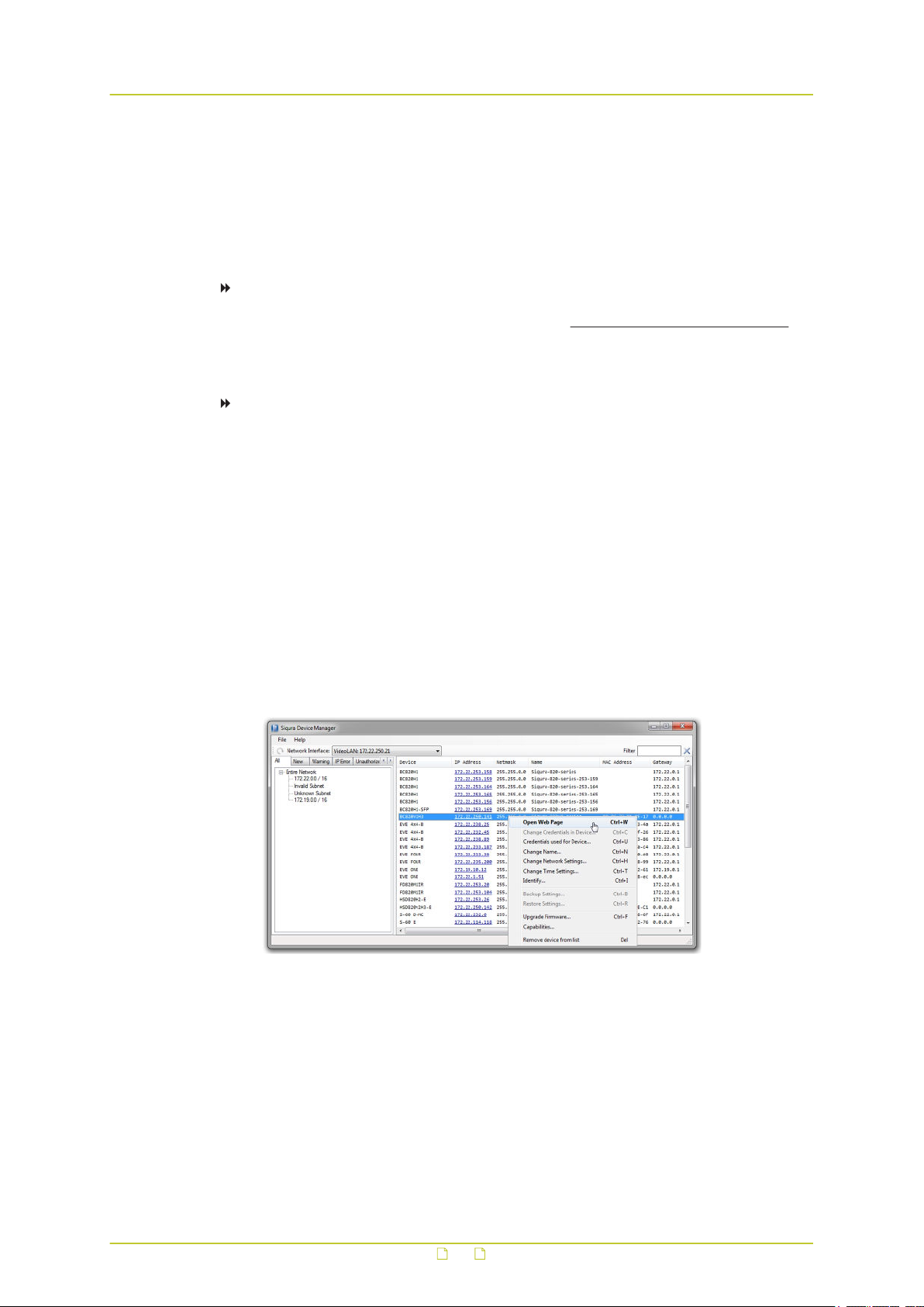
To connect to the unit via Device Manager
1 Start Device Manager
The network is scanned and detected devices appear in the List View pane.
2 If multiple network adapters exist, select the appropriate adapter to scan the network
that you wish to connect to.
3 To refresh the List view pane, click the Rescan now button.
4 Use the tabs in the Tree View pane to define the scope of your search.
5 Click the column headings in the List View pane to sort devices by type, IP address, or
name.
6 Use the Filter box, to search for a specific series or model.
7 To connect to the webpages of the S620 E, double-click its entry in the device list,
- or -
Right-click the entry, and then click Open Web Page.
The login page of the S620 E is opened in your web browser.
Connect to a device via Device Manager
29

Access the webpages
8.4 Connect via UPnP
Universal Plug and Play (UPnP) support is enabled by default on the S620 E. With the UPnP
service enabled in Windows (see Appendix: Enable UPnP in Windows), you can access the unit
from Windows Explorer.
To connect to the unit via UPnP
1 In Windows Explorer, open the Network folder.
Detected devices in the same subnet as the computer are displayed, including TKH
Security codecs and cameras with UPnP support.
2 Double-click the S620 E,
- or Right-click the unit, and then click View device webpage.
The login page of the S620 E is opened in your web browser.
Connect to a device via Windows Explorer
For more information about UPnP, see Auto Discovery (Device Management chapter).
8.5 Log on to the unit
Users with a valid account for the S620 E can log on to the unit.
To log on to the S620 E
1 On the Login page, click LOGIN.
2 Log on with the account that was created for you.
User name and password are case sensitive.
The default user name set at the factory for the S620 E is "Admin" with password
"1234".
30
 Loading...