

Siqura HSD620, HSD622, HSD626, MSD620, MSD622 Quick Start Manual
Prepare outdoor camer a fo r in stallation
Siqura HSD620/622/626 & MSD620/622
IP PTZ dome w ith day/n ig ht a nd wide d yn am ic r ange
Quick Start Guide
© Siqura B.V. 2014
Version 2.0 (101310-2)
xSD62x QSG (MW10)
Outdoor camera moun ti ng r eq uire ments
Package conte nt s
Cabling ove rv ie w
Install out do or c am er a wi th wall mount
www.siqura.com
www.tkhsecurity-usa.com
22-Pin connecto r de fi nition
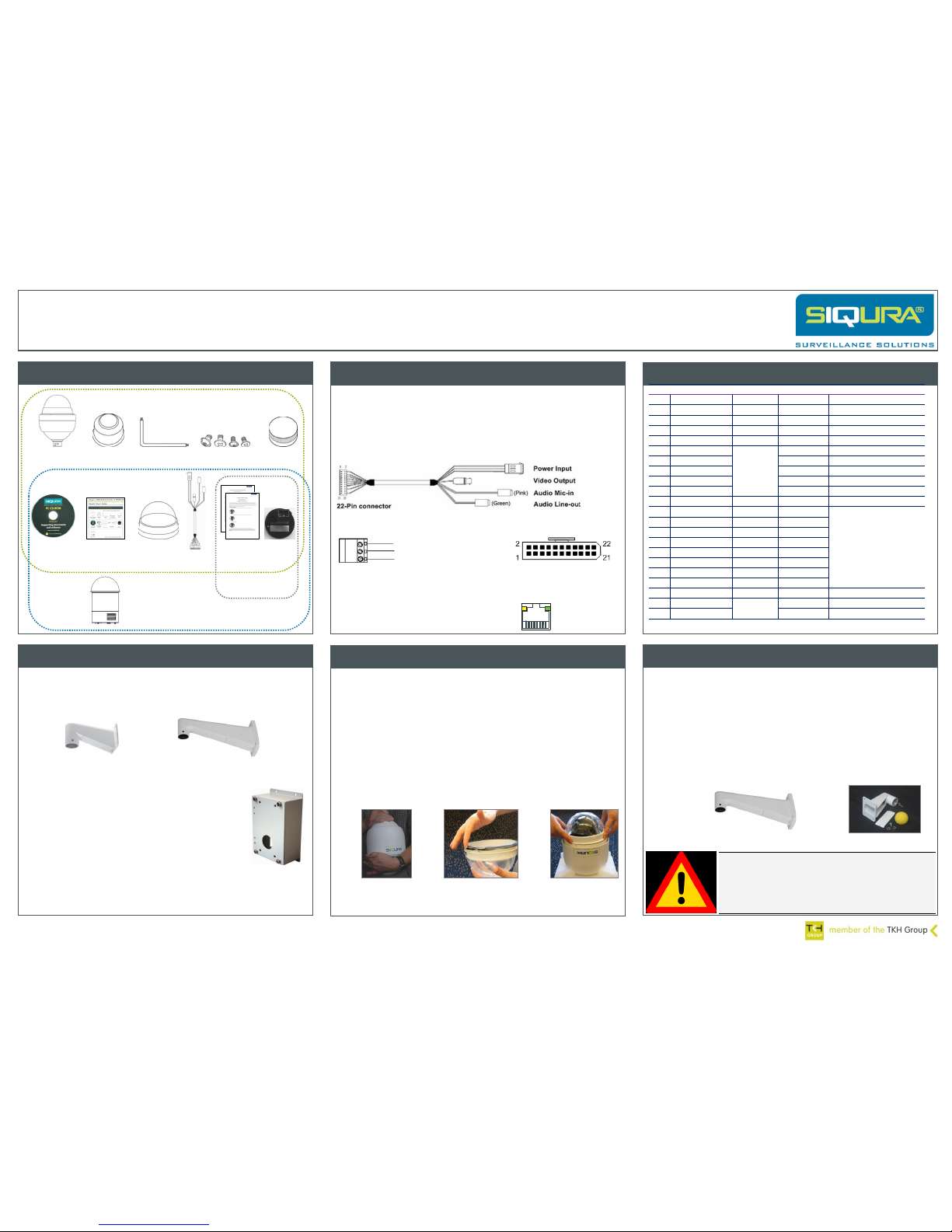
Figure 1 Outdoor camera package contents
Cable
harness
Waterproof
boot
Lubricant
CD (Manuals
and software)
Quick Start
Guide
Optical
cover
SFP
Accessory
Outdoor model with
tube adapter
Security
torx
Screws
(M3, M5 PH, M5 torx)
Indoor
model
For operation, an HSD62x/MSD62x camera requires the following:
A Cat 5 Ethernet cable with an RJ-45 connector
- or (for /SFP models) -
An SFP module as described in the XSNet™ SFP data sheet and fiber optic cable
and connectors compatible with the chosen SFP module.
A cable harness for power, analogue video, and audio transmissions, equipped
with a 22-pin connector for connecting to the camera (table 1).
Figure 3 Cable harness components
24 VAC
Ground (GND)
24 VAC
Figure 4 Power input details
Figure 5 22-pin connector pins
RJ-45 connector LEDs
Green indicates a good network connection.
Yellow verifies network activity.
Figure 6 RJ-45
connector LEDs
Pin
Definition
Cable
Colour
Rating
1
AC 24-1/DC(+)
20/18 AWG
Red
2
Alarm out, NC
White
Photo Relay output 300 V
3
AC 24-2/DC(-)
20/18 AWG
Black 4
Alarm out, NO
White/black
Photo Relay output 300 V
5
FG
20/18 AWG
Yellow
6
Alarm out, COM
24 AWG
Green/black
Photo Relay output 300 V
7
Audio in
Yellow/black
8 Audio out
Orange/black
9
Audio GND
Green/black
10
Audio GND
Brown/black
11
Isolated GND
Blue/white
12
Alarm 1 Red/white
Input 5 V 10 kΩ pull up
Photo Relay output 300V
13
Alarm 2 Purple
14
Alarm 3 Gray
15
Alarm 4 Blue
16
Alarm 5 White/black
17
Alarm 6 Orange/black
18
Alarm 7 Purple/white
19
Alarm 8 Gray/black
20
Alarm GND
Brown/white
Input 5 V 10 kΩ pull up
21
Video GND
20 AWG
Black/gray
22
Video
Red/gray
Table 1 22-pin connector assignments
Figure 7 WM01A Mini Wall Mount
Use one of two types of mounts to install an outdoor HSD62x/MSD62x on a
wall.
Siqura WM01A Mini Wall Mount
Siqura WM07 Long Wall Mount
Figure 8 WM07 Long Wall Mount
The mini wall mount and the long wall mount can be installed
onto a box mount if extra space for the cables is required.
To prepare the outdoor HSD62x/MSD62x for installation
1. Remove the outdoor tube adaptor by rotating counter clockwise (figure 9a).
2. Make a note of the IP address on the label attached to the cylindrical heat sink.
3. Remove the PE cloth and take off the lens cap.
4. Generously apply the supplied lubricant to the optical cover’s waterproof boot to
ensure an IP66 quality installation (figure 9b).
5. Loosen the screw head alignment pins on the dome cover by turning clockwise
and line up the alignment pin and screws on the optical cover with the holes in
the dome body.
6. Attach the optical cover to the dome body by pressing gently down on the sides
of the dome cover (figure 9c).
7. Turn the screw head alignment pins counter-clockwise with a suitable
screwdriver to lock the dome into place and secure the dome with the included
Phillips-head or torx screw.
Figure 9a
Remove outdoor tube
adapter
Figure 9b
Lubricate optical cover’s
waterproof boot
Figure 9c
Attach optical cover
to dome body
Outdoor installation requires the following items:
Dome camera
Supplied waterproof boot
Wall mount (optional accessory)
Screws and screw anchors
Screwdriver and drill
To mount the outdoor HSD62x/MSD62x with a wall mount
1. Make a hole in the wall or metal access plate for the cables and secure the
supplied cable gland in the wall.
2. Ensure that the weather resistant gasket is correctly attached to the mount.
3. Thread the cables through the wall mount and screw it onto the wall.
4. Attach the waterproof boot to the wall mount.
5. Thread the cables through the outdoor tube adaptor and fix it to the wall
mount with the supplied screws and washers.
6. Clip the safety wire to the dome camera.
7. To keep insects out, block the cable entry hole with the supplied sponge.
8. Connect the cables to the dome camera.
9. Attach the dome to the outdoor tube adaptor and fasten them together with
the supplied screws.
Warning: Fully torque down the mounting bolt that attaches the
WM02 tube adapter to the mounting bracket to prevent any
movement of the camera due to wind, vibration, etc.
Make sure the camera cannot move at all in its bracket after
installation. Any movement of the camera in its bracket can
compromise positional accuracy.
Figure 11 Mini wall mount
Figure 10 Long wall mount
Figure 2 Indoor camera package contents
Instruction
leaflets
HSD models only
Log on to the cam er a we bpages
View video stream in vi de o player (VLC)
Indoor camera m ou nt in g requirements
Install indoor ca me ra w ith flush mount
Install Siqur a De vi ce Manager
Access the came ra v ia S iq ura Device Mana ge r
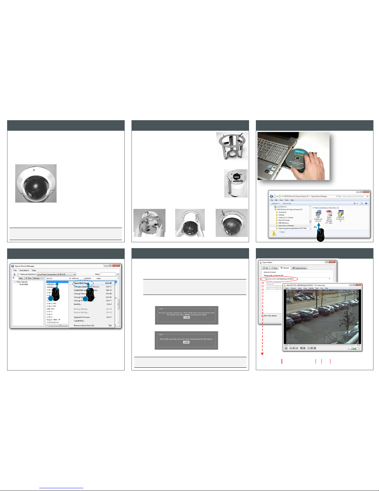
To mount the HSD620/MSD620 with a flush mount
1. Detach the removable wing from the flush mount
(figure 13a).
2. With the supplied screw, attach the separated wing to
the dome body (figure 13b).
3. Place the red sticker on the ceiling and cut the circle
out of the ceiling.
4. Insert the flush mount into the hole.
5. Rotate the flush mount’s wings to fix the mount at the
edge of the ceiling opening and tighten their screws
(figure 13c).
6. Thread the cable harness and Ethernet cable through
the centre hole of the flush mount and connect them to
the dome body.
7. Mount the dome body into the bracket and rotate
clockwise (figure 13d).
8. Tighten the fixing screw, to secure the dome body
(figure 13e).
9. Detach the optical cover, if necessary, and attach the
decorative ring to the mount.
10. Reattach the optical cover.
Note: Insert a ceiling panel prior to installing the dome camera to reinforce the
ceiling's strength, if necessary. A ceiling panel may be needed, for example, when
installing the dome camera in a suspended ceiling.
Indoor installation requires the following items:
Dome camera
CM04 Flush Mount (optional accessory)
Decorative ring (supplied with flush mount)
Screw (supplied with flush mount)
Red sticker (supplied with flush mount)
Tool for cutting a circular hole in the ceiling
Screwdrivers (slotted and Phillips)
Figure 12 In-ceiling mounting
Figure 13c
Figure 13a
Figure 13b
Figure 13e
Figure 13d
To log on to the camera
1. On the Login page, click LOGIN.
2. Log on with the account that was created for you.
User name and password are case sensitive.
The factory-set user name is "Admin" with password "1234" (figure 16a).
Note: To prevent unauthorised access from people using the default account,
we recommend that the administrator changes the default password after first
login and creates separate user accounts as needed. This also removes the
default account details from the login screen (figure 16b).
3. Click OK or press ENTER.
On successful login, the Live Video page appears.
Important: Log on as “admin” with an empty password if the firmware version of the
camera server board is lower than v4.0.
Figure 14
Install Siqura Device
Manager from Siqura
Product CD
Figure 15 Camera detected by Siqura Device Manager
Figure 16a Access with default Admin account only
Figure 16b Access with user account created by Admin
Figure 17
Video stream from
camera opened and
viewed in VLC Media
Player
rtsp://10.0.231.156/VideoInput/1/h264/1
camera IP address
video input number
media type
video encoder number
10.0.0.0/8
HSD626
2
1
 Loading...