

Siqura FD820 Quick Start Manual
Step 4: Accessing t he C am er a
Siqura FD820 IP Cameras
High-Definiti on F ix ed -D om e Style
Quick Start Guide
© Siqura B.V. 2012
Version 1.0 (120105-1)
FD820 QSG (MW07SP2)
Step 3: Powering Up
To power the FD820 with PoE
Connect the RJ-45 connector to an appropriate PSE network switch.
Use Cat 5 Ethernet cable that does not exceed 100 meters in length.
Connect to a hub or switch with straight-through cable. Use crossover
cable to connect directly to a PC.
Note that PoE cannot be used with the heater.
To power the FD820 with AC24V/DC12V
Connect to the DC/AC power source as
indicated in table 1 and figure 5.
Note that the supplied DC power
adapter is for indoor use only.
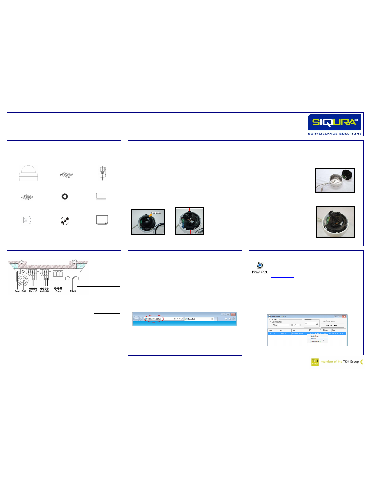
Figure 5 FD820 Printed Circuit Board (PCB)
connectors
Step 1: Product Invento ry
Figure 1 FD820 package contents
Before you proceed, make sure that your FD820 package contains the
items listed below.
FD820 camera
Self-tapping screws (x4)
CD (manuals
and search tool)
Rubber washers (x6)
Security TORX
Plastic screw anchors (x4)
Quick Start Guide
1.5A power adapter
(indoor use only)
Step 2: Hard Wall or Ce il in g In stallation
FD820 cameras can be installed directly on a wall or ceiling.
Make sure that the provided surface has sufficient strength to support the camera.
If you use Power over Ethernet (PoE), check that there is adequate access to an IEEE 802.3AF Power Sourcing Equipment (PSE) enabled network.
Step 1: Remove the camera from the dome housing
1. Use the supplied security TORX to unscrew the:
- housing cover
- camera from the housing
2. Gently press both sides of the inner cover and
remove it from the dome unit (figure 2 – left).
3. Press the snap-on sides of the camera and
detach it from the dome housing (figure 2 –
right).
Step 2: Mount the dome housing
Attach the dome housing to the wall or ceiling with
the supplied screws and screw anchors.
Step 3: Connect the cables
1. Thread the power, Ethernet, and possibly audio and
alarm device cables through the side or back conduit
entry (figure 3).
2. Connect the cables to the FD820.
Step 4: Insert the snap-on module into the dome housing
Snap the camera back into the dome housing
(figure 4).
Figure 3 Connect the cables and lead
them through the conduit entry
Connector
Pin
Definition
DC 12V
1
Power
2
Reserved
3
GND
AC 24V
1
Power-1
2
GND 3 Power-2
Table 1 Power connector pin
definitions
Step 5: Device Sear ch
Use the Device Search application to discover and
change the IP address of the camera.
DeviceSearch.exe can be found on the supplied CD or at
www.siqura.com. This application detects and lists all the
Siqura IP cameras found on the network.
To explore your network for installed devices
1. Start the Device Search application.
2. Click the Device Search button.
If a security alert window displays, click Unblock to continue.
3. Right-click a device and select Browse to access the internal
settings of the camera via a web interface.
Figure 7 Click Browse to open the webpages of the camera
Power terminal block
Figure 2 Remove the inner cover (left) and detach
the camera from the dome housing
Figure 4 Reattach the camera to the
dome housing
The internal settings of the FD820 can be accessed directly via a
web interface.
Use only Internet Explorer 6.x or higher.
The IP camera’s default IP address is printed on a label located on
the bottom of the camera.
The default logon user name and password are Admin / 1234. Both
are case sensitive.
To access the camera’s internal settings
Type the IP address of the camera in the address bar of your web
browser (figure 6).
To view the webpages of the camera properly
Install the add-on, Siqura Viewer.
Enable ActiveX controls.
www.siqura.com
www.tkhsecurity-usa.com
Figure 6 Entering the IP address of the camera into the address bar of your
browser
Step 10: Connecting A ud io
If microphones and speakers are configured to the network, the
FD820 camera can be used to provide a two-way audio channel.
Step 1: Connect the audio input and output connectors to the back of the
camera (figures 5 and 13, and table 2).
Step 2: In the internal web pages, go to Streaming > Audio and select one
of the following options:
Full-duplex (Talk and listen simultaneously)
Half-duplex (Talk or listen, not at the same time)
Simplex (Talk only)
Simplex (Listen only)
Disable
Audio I/O
1
Input
2
GND 3 Audio Out-R
4
Audio Out-L
Table 2 Audio in and out connector
assignments
Connecting an alarm device to the FD820 camera input can trigger an
output action to occur based on contact closure settings.
Step 1: Connect the alarm relay connectors to the I/O terminal block
(figures 5 and 14, and table 3).
Step 2: In the internal web pages, go to the System tab. Using the
Application, Motion Detection, and Tampering pages, configure the alarms as
desired.
Alarm I/O
1
Output +
2
Output -
3
Input + 4 Input -
Table 3 Alarm connector assignments
Step 11: Setting the Alar ms
Figure 14 Alarm in and out
connectors
Figure 13 Audio in and out
connectors
Step 6: Establish in g th e Ne tw or k Property
To change the network property of the camera
1. In the Device Search application, right-
click the camera and select Network Setup.
2. Click to select either the:
DHCP check box, and record the MAC
address of the camera for future
identification.
OR
Static IP check box, and then enter the
IP address of the camera, the subnet
mask, the default gateway, and the
DNS server in the appropriate boxes.
3. Click Apply to confirm the new settings
and wait for one minute before searching
for the camera using Device Search.
Figure 8 Assigning a static IP
address through Network Setup
please note A DHCP server must be installed on the network in order
to apply DHCP network support.
Step 7: Internal We b Pa ge s
Across the top of the FD820 home page are five main menu items:
Home
Users can monitor a live video stream or double-click the image to
view stream details.
System
Users can set the host name, system time, root password, and other
network related settings.
Streaming
Users can set video and audio formats and compression parameters.
Camera
Users can adjust various camera settings, including exposure, white
balance, brightness, sharpness, contrast, and digital zoom.
Logout
The Logout option signs the user out of the camera’s web pages and
opens the sign in page.
Figure 9 The FD820 web interface menus
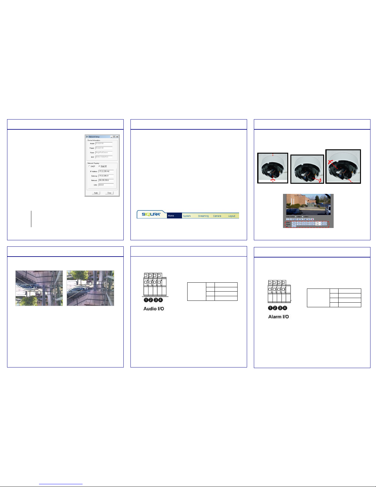
Step 8: Adjusting t he L en s
The FD820 has a motorised lens.
Manually adjust the angle of the camera to monitor the desired area (fig. 10).
Use your web browser (Step 7) to zoom and focus (figure 11). Check the
image quality as you make changes.
Figure 10 Adjust the pan, rotation, and tilt of the camera as necessary
Figure 11 Zoom and
focus buttons on the
FD820 home page
Note: The IR function on FD820 IR models can be set via the Camera menu
(Step 7).
Step 9: Video Rotation
Depending on how the FD820 camera is mounted, you may need to
rotate the camera image.
To select a video rotation type
1. On the Streaming tab, select Video Format from the menu options on
the left.
2. Choose one of the following video rotation types:
Normal video. The camera’s orientation is not modified.
Flip video. The image rotates across the horizontal axis.
Mirror video. The image rotates across the vertical axis.
90 degree clockwise. The image rotates 90° clockwise.
180 degree rotate. The image rotates 180°.
90 degree counterclockwise. The image rotates 90°
counterclockwise.
3. Click Save to confirm settings.
Figure 12 The FD820 installation requires rotation
 Loading...