

Siqura BL2005M1-EI Quick Start Manual
Unpack
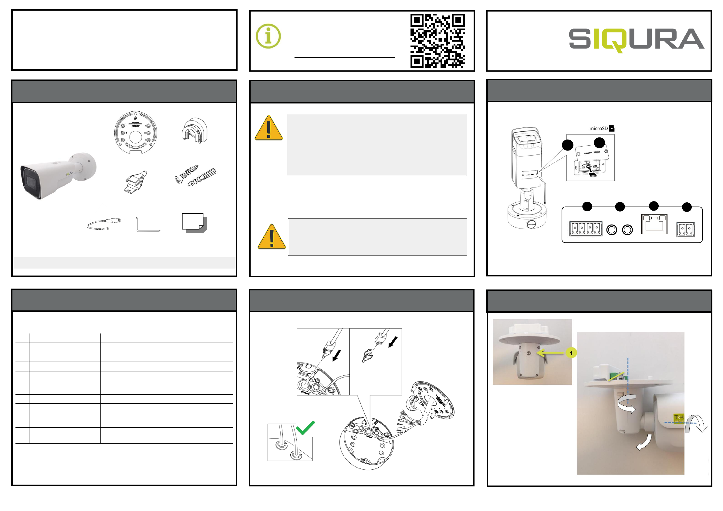
Connector Definition
Installation Notices
Connectors
Pan/Tilt/Rotate
Cabling through Junction Box
BL2005M1-EI
5MP Network Bullet Camera
Quick Start Guide
Find additional manuals, the datasheet,
the EU Declaration of Conformity, and
the latest firmware for this product at:
Siqura.com/downloads/software
Quick Start Guide
Note 1: Subject to modification. Actual product and accessories may differ in appearance.
© Siqura B.V. 2019
Vision 2.0 (01112019)
BL2005M1-EI QSG
Security Torx
NOTE:
IT IS NOT RECOMMENDED TO CONTINUOUSLY (24/7) RECORD WITH THE MICRO
SD CARD, AS THE CAMERA MAY NOT SUPPORT LONG-TERM CONTINOUS DATA
READ/WRITE. CONTACT THE MANUFACTURER OF THE MICRO SD CARD FOR
INFORMATION REGARDING THE RELIABILITY AND THE LIFE EXPECTANCY.
Screws(4x) &
Plastic Screw
Anchors (4x)
CAUTION:
INSTALLATION SHALL BE PERFORMED BY QUALIFIED PERSONNEL ONLY.
INSTALLATION SHALL BE IN ACCCORDANCE WITH LOCAL PROCEDURES.
INSTALLATION WITH POE SHALL BE IN UNEXPOSED NETWORKS.
BATTERY REPLACEMENT SHALL NOT BE APPLIED IN VIEW OF THE RISK OF
EXPLOSION.
IF YOU USE AN EXTERNAL POWER SUPPLY, CONTACT SIQURA TO MAKE SURE
THAT THE POWER SUPPLY HAS THE PROPER POWER SPECIFICATIONS.
MAKE SURE THAT THE POWER SUPPLY COMPLIES WITH LPS REQUIREMENTS.
Camera Unit
BNC Connector
1
2
3
4
5
6
No.
Connector Definition
1
Alarm I/O
Alarm I/O connection
2
Audio
Audio Line in/Out
3
RJ
-45 Port
(Contact Siqura for a
compatible PoE
injector.)
For network and PoE connections
4
Power (DC12V)
Power connection
5
SD Card Slot
Insert the SD card into the card slot to store
videos and snapshots. Do not remove the SD card
when the camera is powered on.
6
Reset Button
Press the button with a proper tool for at least 20
seconds to restore the system.
Table 1 Connector definition
Pin Pusher
Pipe Cover
Mounting Adapter
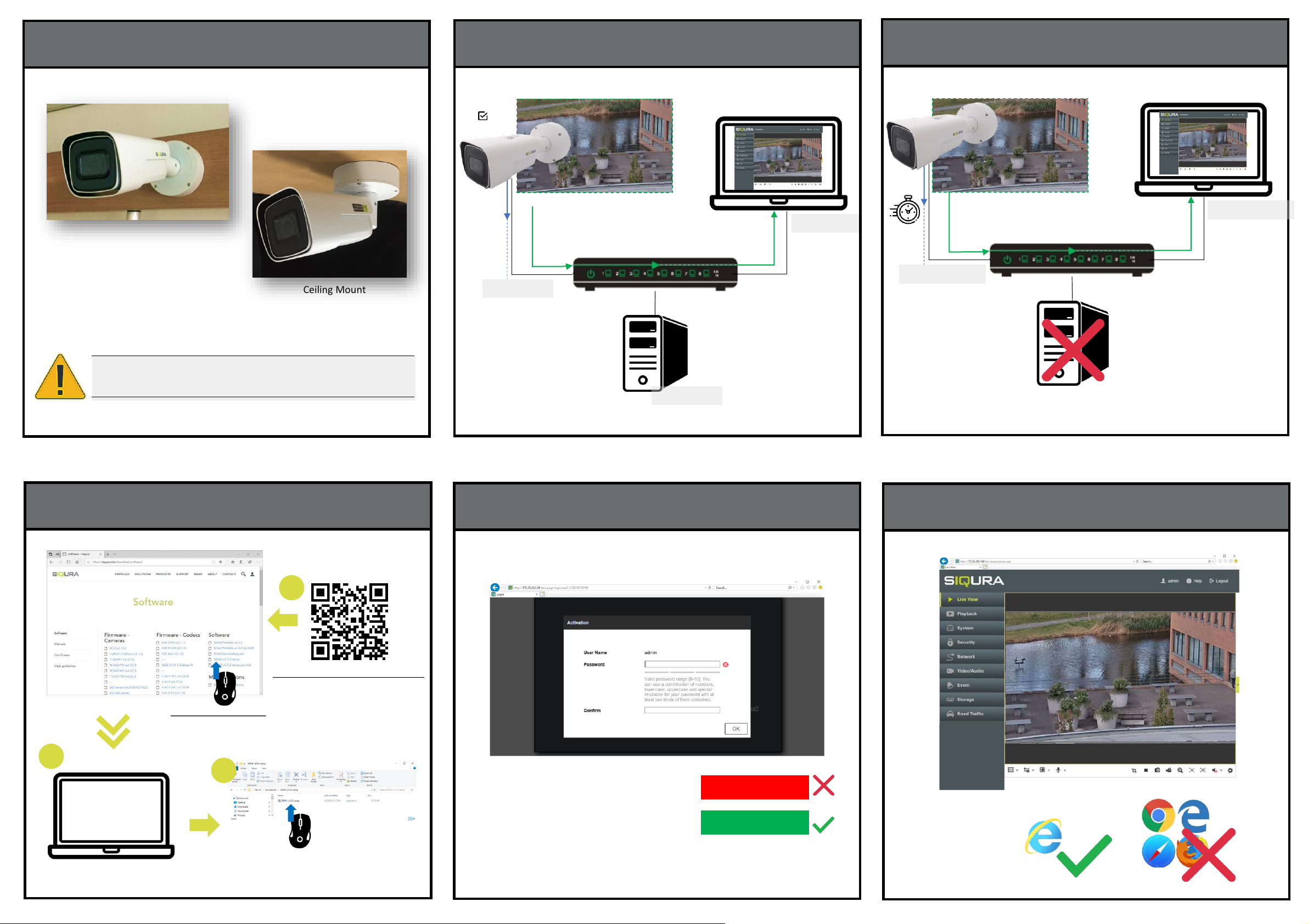
Accessing the camera – Fixed IP address
Auto detect with SDM2
Browser-based Viewer
IP = 192.168.0.x
Network Switch
DHCP Server
Siqura.com/downloads/software
SDM2-vx.xx-setup.zip
2
3
1
11
IP = 192.168.0.x
30s
1sttime camera login
qwer1234
x6W@oM0a!9#F
Set a strong password
IP = 10.x.y.z
Network Switch
DHCP Server
IP = 10.x.y.z
IP = 10.x.y.z
DHCP
Accessing the camera - DHCP Server
Mounting
Wall/Pole Mount
Ceiling Mount
NOTE:
OTHER THAN MOUNTING ABOVE, OTHER MOUNTING MAY CAUSE POTENTIAL
WATER LEAKAGE AT CAMERA, WHICH IS NOT INCLUDED IN WARRANTY.
 Loading...