

Siqura FD1103, BL1103, BC1103 User Manual
BC1103/BL1103/FD1103
3 MP Intelligent IP cameras
User Manual

Note: To ensure proper operation, please read this manual thoroughly before using the
product and retain the information for future reference.
Copyright © 2016 Siqura B.V.
All rights reserved.
BC1103/BL1103/FD1103
User Manual v1 (162303-1)
AIT55
Nothing from this publication may be copied, translated, reproduced, and/or published by
means of printing, photocopying, or by any other means without the prior written permission
of Siqura.
Siqura reserves the right to modify specifications stated in this manual.
Brand names
Any brand names mentioned in this manual are registered trademarks of their respective
owners.
Liability
Siqura accepts no liability for claims from third parties arising from improper use other than
that stated in this manual.
Although considerable care has been taken to ensure a correct and suitably comprehensive
description of all relevant product components, this manual may nonetheless contain errors
and inaccuracies. We invite you to offer your suggestions and comments by email via
t.writing@tkhsecurity.com. Your feedback will help us to further improve our documentation.
How to contact us
If you have any comments or queries concerning any aspect related to the product, do not
hesitate to contact:
Siqura B.V.
Zuidelijk Halfrond 4
2801 DD Gouda
The Netherlands
General : +31 182 592 333
Fax : +31 182 592 123
E-mail : sales.nl@tkhsecurity.com
WWW : www.siqura.com
2

Contents
1 About this manual ..................................................................................... 5
2 Safety and compliance .............................................................................. 6
2.1 Safety instructions ............................................................................... 6
2.2 Compliance information ........................................................................ 8
3 Connect to network ................................................................................... 9
3.1 System requirements ........................................................................... 9
3.2 Connect the camera to a LAN ................................................................ 10
3.3 Connect the camera to a WAN ............................................................... 11
4 Get access to the camera .......................................................................... 14
4.1 Get access via web browser .................................................................. 14
4.2 Get access via Siqura Device Manager .................................................... 14
4.3 Get access via UPnP ............................................................................. 16
4.4 Log on to the camera ........................................................................... 17
4.5 Install the videoplayer plug-in ............................................................... 18
5 Live View .................................................................................................. 19
6 Playback ................................................................................................... 25
7 System ...................................................................................................... 27
7.1 Basic Information ................................................................................ 27
7.2 Time Settings ...................................................................................... 28
7.3 Upgrade & Maintenance ........................................................................ 29
7.4 RS-485 .............................................................................................. 31
7.5 Log .................................................................................................... 32
7.6 Local Configuration .............................................................................. 33
8 Security ..................................................................................................... 35
8.1 User Management ................................................................................ 35
8.2 Authentication ..................................................................................... 36
8.3 IP Address Filter .................................................................................. 38
9 Network .................................................................................................... 39
9.1 TCP/IP ............................................................................................... 39
9.2 DDNS ................................................................................................. 41
9.3 PPPoE ................................................................................................ 43
9.4 SNMP ................................................................................................. 44
9.5 802.1X ............................................................................................... 45
9.6 QoS ................................................................................................... 45
9.7 NAT ................................................................................................... 46
9.8 HTTPS ................................................................................................ 47
9.9 Mail ................................................................................................... 49
9.10 FTP .................................................................................................... 50
10 Video/Audio .............................................................................................. 52
10.1 Streaming .......................................................................................... 52
10.2 Picture Adjustment .............................................................................. 54
10.3 Text Overlay ....................................................................................... 57
3

Contents
10.4 Picture Overlay .................................................................................... 58
10.5 Privacy Mask ....................................................................................... 59
10.6 ROI ................................................................................................... 60
10.7 Target Cropping .................................................................................. 61
11 Events ....................................................................................................... 63
11.1 Motion Detection ................................................................................. 64
11.2 Video Tampering ................................................................................. 66
11.3 Alarm Input ........................................................................................ 68
11.4 Alarm Output ...................................................................................... 70
11.5 Exception ........................................................................................... 71
11.6 Audio Exception Detection .................................................................... 72
11.7 Defocus Detection ................................................................................ 73
11.8 Scene Change Detection ....................................................................... 74
11.9 Face Detection .................................................................................... 76
11.10 Intrusion Detection .............................................................................. 78
11.11 Line Crossing Detection ........................................................................ 80
11.12 Region Entrance Detection .................................................................... 82
11.13 Region Exiting Detection ....................................................................... 84
11.14 Unattended Baggage Detection .............................................................. 86
11.15 Object Removal Detection ..................................................................... 88
11.16 Counting ............................................................................................ 90
12 Storage ..................................................................................................... 93
12.1 HDD Management ................................................................................ 93
12.2 Record Schedule .................................................................................. 94
12.3 Capture .............................................................................................. 96
12.4 Net HDD ............................................................................................. 97
Index ...................................................................................................... 99
4

1 About this manual
What's in this manual
This manual gives you the information you need to use Siqura's BC1103/BL1103/FD1103
cameras. It tells:
● How to get access to the camera
● How to communicate with the camera
● How to operate the camera
● How to configure the settings of the camera
Where to find more information
All product-specific manuals, such as Quick Start Guides, Installation Manuals and User
Manuals, are available as PDF download at www.siqura.com. We advise you to make sure that
you have the latest version of this manual. To obtain the technical specifications of a camera,
download the datasheet of the specific model.
Who this manual is for
These instructions are for all professionals who will configure and operate Siqura BC1103/
BL1103/FD1103 Series cameras.
What you need to know
You will have a better understanding of how the camera works if you are familiar with:
● Camera technologies
● CCTV systems and components
● Ethernet network technologies and Internet Protocol (IP)
● Windows environments
● Video, audio, and contact closure transmissions
● Video compression methods
Before you continue
Before you continue, read and obey all instructions and warnings in this manual. Keep this
manual with the original bill of sale for future reference and, if necessary, warranty service.
When you unpack your product, make sure there are no missing or damaged items. If any
item is missing, or if you find damage, do not install or operate this product. Ask your supplier
for assistance.
Why specifications may change
At Siqura, we are committed to delivering high-quality products and services. The information
given in this manual was current when published. As we continuously seek to improve our
products and user experience, all features and specifications are subject to change without
notice.
We like to hear from you!
Customer satisfaction is our first priority. We welcome and value your opinion about our
products and services. Should you detect errors or inaccuracies in this manual, we would be
grateful if you would inform us. We invite you to offer your suggestions and comments via
t.writing@tkhsecurity.com. Your feedback helps us to further improve our documentation.
5
2 Safety and compliance
This chapter provides safety instructions and compliance information. It also tells how to
dispose of the product at the end of its service life.
In This Chapter
2.1 Safety instructions.................................................................................................. 6
2.2 Compliance information........................................................................................... 8
2.1 Safety instructions
These instructions are intended to make sure that the user can use the product correctly and
avoid danger or property loss.
The precaution measure is divided into ‘Warnings’ and ‘Cautions’:
● Warnings: Serious injury or death may be caused if any of these warnings are neglected.
● Cautions: Injury or equipment damage may be caused if any of these cautions are
neglected.
Warnings Follow these safeguards to
prevent serious injury or
death.
Warnings
● Use a power adapter which can meet the safety extra low voltage (SELV)
standard and source it with 12 Vdc or 24 Vac (depending on the model)
according to the IEC60950-1 and Limited Power Source standard.
● To reduce the risk of fire or electrical shock, do not expose this product to
rain or moisture.
● This installation should be made by a qualified service person and should
conform to all the local codes.
● Install blackout equipment into the power supply circuit for convenient
supply interruption.
● Make sure that the ceiling can support more than 50 (N) Newton if the
camera is fixed to the ceiling.
● If the product does not work properly, contact your dealer or the nearest
service centre. Never attempt to disassemble the camera yourself. We shall
not assume any responsibility for problems caused by unauthorised repair or
maintenance.
Cautions Follow these precautions to
prevent potential injury or
material damage.
6
Safety and compliance
Cautions
● Make sure the power supply voltage is correct before using the camera.
● Do not drop the camera or subject it to physical shock.
● Do not touch the sensor modules with your fingers. If cleaning is necessary,
use a cleaning cloth with a bit of ethanol and wipe it gently. If the camera
will not be used for an extended period of time, put on the lens cap to
protect the sensor from dirt.
● Do not aim the camera lens at strong light such as the sun or an
incandescent lamp. The strong light can cause fatal damage to the camera.
● The sensor may be burned out by a laser beam, so if any laser equipment is
used, make sure that the surface of the sensor is not exposed to the laser
beam.
● Use the unit under conditions where the temperature remains within the
range given in the Technical Specifications of this product. You can
download the datasheet of the camera at www.siqura.com.
● Do not install the camera in a dusty or damp environment, and do not
expose it to high electromagnetic radiation.
● To avoid heat accumulation, good ventilation is required to ensure a proper
operating environment.
● Keep the camera away from water and any liquid.
● While shipping, the camera should be packed into its original packing.
● Improper use or replacement of the battery may result in the hazard of
explosion. Use the battery type recommended by the manufacturer.
Cautions
The following cautions apply to cameras with IR functionality. Be sure to follow them to
prevent IR reflection.
● Dust or grease on the dome cover will cause IR reflection. Do not remove
the dome cover film until the installation is finished. If there is dust or
grease on the dome cover, clean the dome cover with a clean soft cloth and
isopropyl alcohol.
● Make sure that the installation location does not have any reflective surfaces
of objects that are too close to the camera. The IR light from the camera
may reflect back into the lens causing a reflection in the video image.
● The foam ring around the lens must be seated flush against the inner
surface of the bubble to isolate the lens from the IR LEDS. Fasten the dome
cover to the camera body so that the foam ring and the dome cover are
attached seamlessly.
7
Safety and compliance
2.2 Compliance information
FCC compliance
This equipment has been tested and found to comply with the limits for a digital device,
pursuant to part 15 of the FCC Rules. These limits are designed to provide reasonable
protection against harmful interference when the equipment is operated in a commercial
environment. This equipment generates, uses, and can radiate radio frequency energy and, if
not installed and used in accordance with the instruction manual, may cause harmful
interference to radio communications. Operation of this equipment in a residential area is
likely to cause harmful interference in which case the user will be required to correct the
interference at his own expense.
FCC Conditions
This device complies with part 15 of the FCC Rules. Operation is subject to the following two
conditions:
1 This device may not cause harmful interference.
2 This device must accept any interference received, including interference that may cause
undesired operation.
Industry Canada ICES-003 Compliance
This device meets the CAN ICES-3 (A)/NMB-3(A) standards requirements.
EU Conformity Statement
This product and - if applicable - the supplied accessories too are
marked with "CE" and comply therefore with the applicable
harmonised European standards listed under the EMC Directive
2004/108/EC, the RoHS Directive 2011/65/EU.
2012/19/EU (WEEE directive): Products marked with this symbol
cannot be disposed of as unsorted municipal waste in the European
Union. For proper recycling, return this product to your local supplier
upon the purchase of equivalent new equipment, or dispose of it at
designated collection points. For more information see:
www.recyclethis.info.
2006/66/EC (battery directive): This product contains a battery that
cannot be disposed of as unsorted municipal waste in the European
Union. See the product documentation for specific battery
information. The battery is marked with this symbol, which may
include lettering to indicate cadmium (Cd), lead (Pb), or mercury
(Hg). For proper recycling, return the battery to your supplier or to a
designated collection point. For more information see:
www.recyclethis.info.
8

3 Connect to network
This chapter gives instructions for connecting the camera to the network.
In This Chapter
3.1 System requirements.............................................................................................. 9
3.2 Connect the camera to a LAN................................................................................. 10
3.3 Connect the camera to a WAN................................................................................ 11
3.1 System requirements
To open communication with the camera, you need:
● A computer with a web browser installed.
● An IP connection between the computer and the camera.
Computer
The browsing computer should meet the following system requirements:
Item Description
Operating System Microsoft Windows 7 / Server 2008 32 bits
CPU Intel Pentium IV 3.0 GHz or higher
RAM 1 GB or higher
Display 1024×768 resolution or higher
Web browser Internet Explorer 7.0 and higher, Apple Safari 5.02 and higher,
Mozilla Firefox 5 and higher, and Google Chrome 8 and higher
IP connection
You can connect the network camera to:
● A local area network (LAN)
● A wide area network (WAN)
Note: Be aware that using this product with Internet access may pose serious threats to
your network security. To avoid network attacks and information leakage, strengthen your
security against intrusions.
To ensure the network security of the network camera, we advise you to inspect and
maintain the network camera at specific intervals. If the product does not work properly,
contact your sales representative.
9
Connect to network
3.2 Connect the camera to a LAN
To view (live) video from the camera and configure its settings, there must be an IP
connection between the camera and a computer.
Important: The network settings of the camera and the computer should be such that they
are on the same subnet.
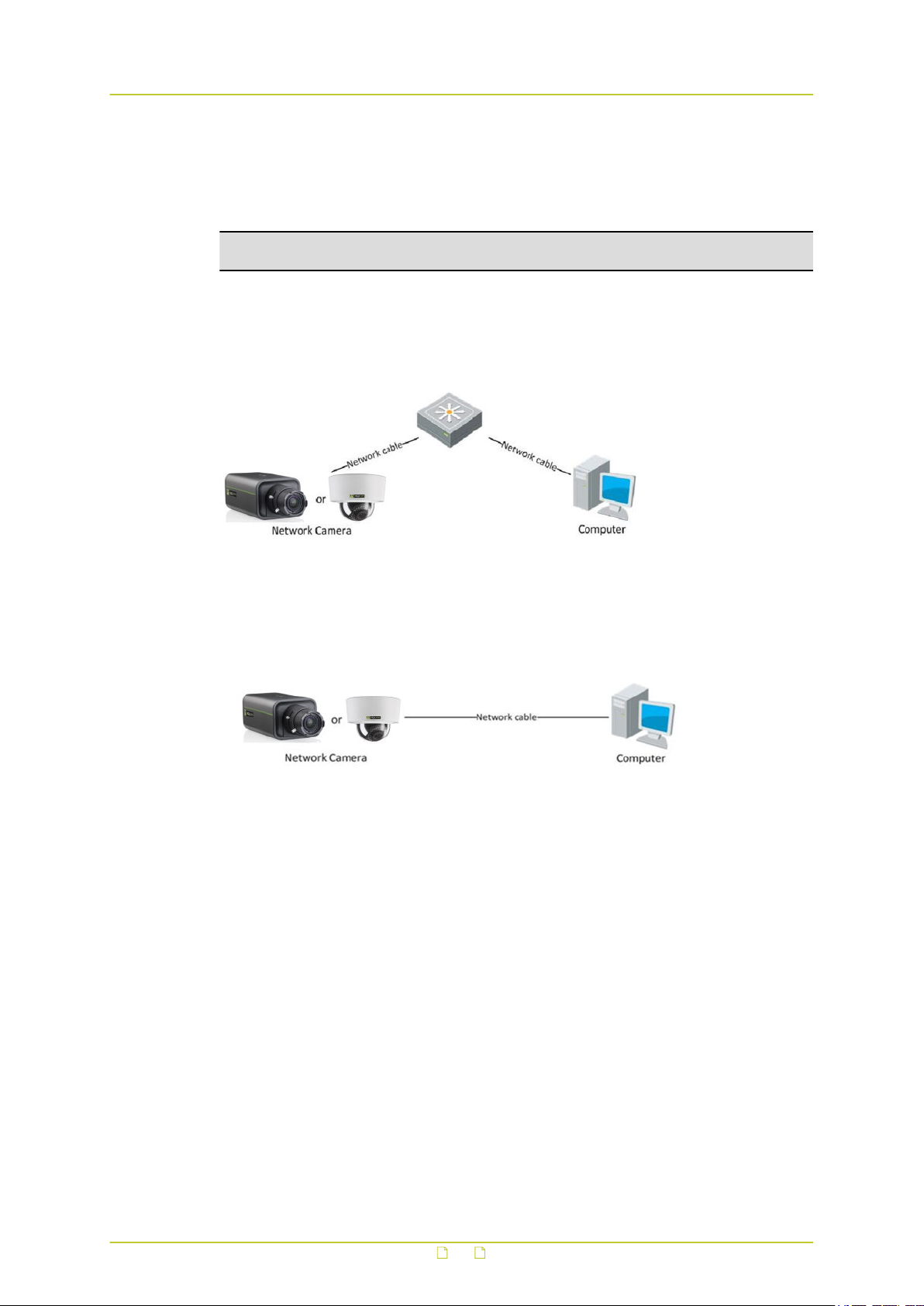
Connection via switch or router
Generally, the network camera and the computer are connected via a switch or a router.
Direct connection
To bring the network camera into the same subnet as the computer (or to test the camera),
connect the two devices directly with a network cable.
Bring the camera and computer into the same subnet
Take the following steps to connect to the network camera from the computer:
1 Set the network adapter of the computer to the factory-set subnet of the camera.
(Control Panel > Network and Sharing Center > Change adapter settings ... >
Properties ... )
For the default network settings of the camera, see Default settings (below) .
2 Connect the two devices with a network cable.
3 Open the web interface of the camera from a web browser on the computer.
For details, see Get access via web browser.
For information about Siqura Device Manager, see Get access via Siqura Device
Manager.
Default settings
Out of the box, the camera has these settings:
● IP address: 192.168.1.64
10
Connect to network
● DHCP: enabled
● UPnP: enabled
● Logon: not required
Add the camera to the intended subnet
Via the web interface of the camera, you can change its network settings to add it to the
subnet it will be used in.
1 On the Network page, click the TCP/IP tab.
2 Set the IP address of the camera to the desired subnet.
3 Click Save.
4 Reboot the camera.
5 (Optional) Configure the network settings of the computer to assign it to the subnet set
in step 2.
With both devices on the same subnet, you can reopen communication between the
computer and the camera.
3.3 Connect the camera to a WAN
This section explains how to connect the network camera to the WAN with a static or dynamic
IP address.
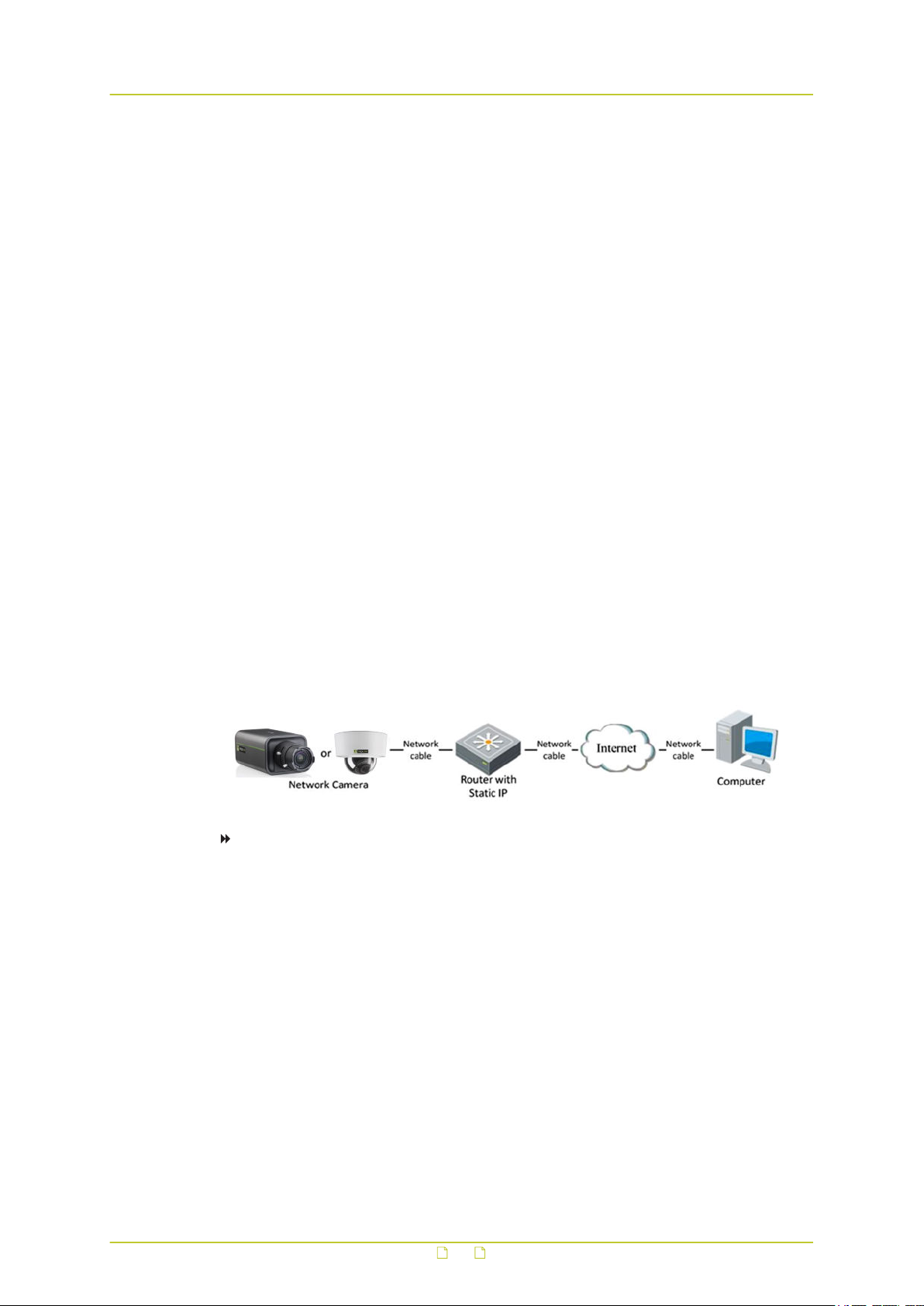
Static IP connection
Before you start, obtain a static IP address from an Internet Service Provider (ISP). With the
static IP address, you can connect the network camera via a router.
To connect the network camera via a router
1 Establish a connection between the network camera and the router.
2 Assign a LAN IP address, subnet mask and gateway address.
For more information about the IP address configuration of the camera, see Connect the
camera to a LAN.
3 Save the static IP in the router.
4 Set the port mapping.
Use 80, 8000, and 554 as ports, for example.
The steps for port mapping vary according to the different routers. If necessary, contact
the router manufacturer for assistance with port mapping
5 Visit the network camera through a web browser or client software over the internet.
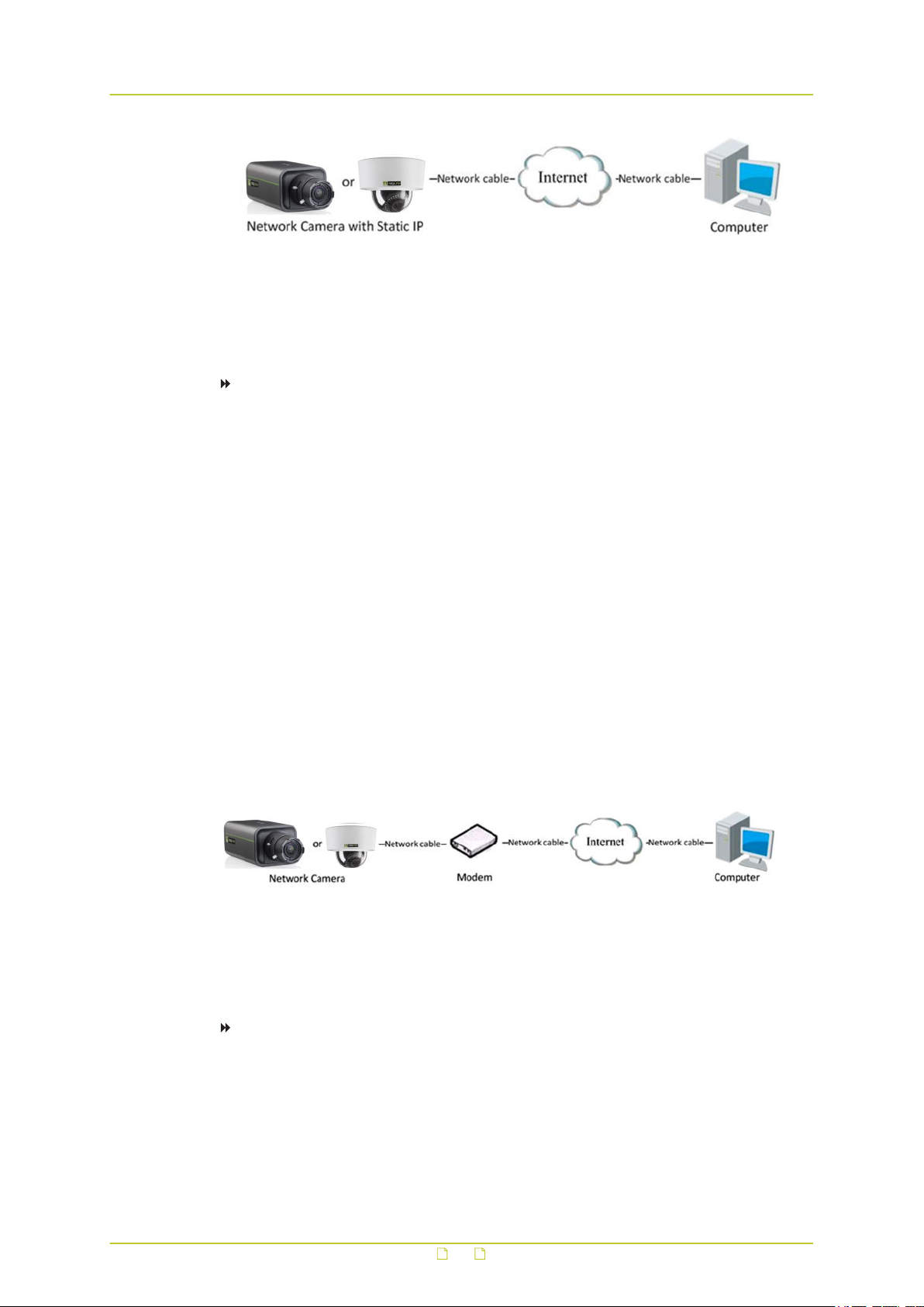
Directly connect the network camera with a static IP address
You can also save the static IP on the camera and directly connect it to the internet without
using a router.
11
Connect to network
Dynamic IP connection
Before you start, obtain a dynamic IP address from an Internet Service Provider (ISP). With
the dynamic IP address, you can connect the network camera via a modem or a router.
To connect the network camera via a router
1 Establish a connection between the network camera and the router.
2 On the camera, assign a LAN IP address, subnet mask and gateway address.
For more information about the IP address configuration of the camera, see Connect the
camera to a LAN.
3 In the router, set the PPPoE user name, password and confirm the password.
4 Set the port mapping.
Use 80, 8000, and 554 as ports, for example.
The steps for port mapping vary according to the different routers. If necessary, contact
the router manufacturer for assistance with port mapping.
5 Apply a domain name from a domain name provider.
6 Configure the DDNS settings in the setting interface of the router.
7 Visit the camera via the applied domain name.
Connect the network camera via a modem
This camera supports the PPPoE auto dial-up function. The camera gets a public IP address by
ADSL dial-up after the camera is connected to a modem. You need to configure the PPPoE
parameters of the network camera.
The obtained IP address is dynamically assigned via PPPoE, so the IP address always changes
after rebooting the camera. To solve the inconvenience of the dynamic IP, you need to get a
domain name from the DDNS provider (for example, DynDys.com). Follow the steps below to
set a normal domain name resolution and a private domain name resolution to solve the
problem.
To set normal domain name resolution
1 Apply a domain name from a domain name provider.
2 On the DDNS tab of the Network page in the camera, configure the DDNS settings.
3 Visit the camera via the applied domain name.
12

Connect to network
To set private domain name resolution
1 Install and run the IP Server software on a computer with a static IP.
2 Access the network camera through the LAN through a web browser.
3 On the DDNS tab of the Network page in the camera, select Enable DDNS.
4 In the DDNS Type list, select IPServer.
13

4 Get access to the camera
The webpages of the camera offer a user-friendly interface for configuring its settings and
viewing live video over the network. This chapter explains how to log on to the built-in web
server.
In This Chapter
4.1 Get access via web browser....................................................................................14
4.2 Get access via Siqura Device Manager..................................................................... 14
4.3 Get access via UPnP.............................................................................................. 16
4.4 Log on to the camera............................................................................................ 17
4.5 Install the videoplayer plug-in................................................................................ 18
4.1 Get access via web browser
To connect to the camera via your web browser
1 Open your web browser.
2 Type the IP address of the camera in the address bar.
The factory-set IP address of the camera is 192.168.1.64.
Note that DHCP is enabled by default on the camera. If a DHCP server exists on the
network, the camera may have acquired an IP address from the DHCP address range. In
that case, refer to your system administrator for assistance. You can also use Siqura
Device Manager or UPnP to detect the camera.
3 Press ENTER.
If user accounts have been created for the camera, you are directed to the login page of
the camera (see Log on to the camera).
If no user accounts have been created, the Live View page is opened directly.
4.2 Get access via Siqura Device Manager
Siqura Device Manager is a Windows-based software tool that you can use to manage and
configure Siqura IP cameras and video encoders. The tool automatically locates Siqura devices
on the network and offers you an intuitive interface to set and manage network settings,
configure devices, show device status, and perform firmware upgrade.
To install Siqura Device Manager
1 Download the latest version of Siqura Device Manager at www.siqura.com.
14

Get access to the camera
2 Double-click the setup file.
3 Follow the installation steps to install the software.
To connect to the camera via Siqura Device Manager
1 Start Siqura Device Manager
The network is scanned.
Detected devices appear in the List View pane.
2 If multiple network adapters exist, select the appropriate adapter to scan the network
that you wish to connect to.
3 To perform a manual search, click the Rescan button.
4 Use the tabs in the Tree View pane to define the scope of your search.
5 Click the column headings in the List View pane to sort devices by type, IP address, or
name.
6 To connect to the webpages of the camera, double-click its entry in the device list,
- or -
Right-click the entry, and then click Open Web Page.
If user accounts have been created for the camera, you are directed to the login page of
the camera (see Log on to the camera).
If no user accounts have been created, the Live View page is opened directly.
Change the network settings with Siqura Device Manager
With Siqura Device Manager, you can directly change the network settings of the camera.
To assign a static IP address
1 Go to the list of detected devices, and then right-click the entry for the camera.
2 Click Change Network Settings.
3 In Change Network Settings, click Static IP.
4 Provide the camera with an appropriate IP address, netmask, and gateway address for
the desired network configuration, and then click OK.
5 In the pop-up window indicating that you have successfully changed the settings, click
OK.
6 Wait one minute, and then rescan the network.
7 To access the webpages of the camera, double-click its entry in the list of found devices.
15

Get access to the camera
To assign a DHCP server
1 Record the MAC address of the camera (see the Serial no. column in Siqura Device
Manager) for future identification
2 In the list of detected devices, right-click the device with the network property that you
would like to change.
3 Click Change Network Settings.
4 In Change Network Settings, click Enable DHCP, and then click OK.
5 In the pop-up window indicating that you have successfully changed the settings, click
OK.
6 Wait one minute, and then rescan the network.
You can identify the camera by its MAC address.
7 To access the webpages of the camera, double-click its entry in the list of found devices.
Note: A DHCP server must be installed on the network in order to provide DHCP network
support.
4.3 Get access via UPnP
Universal Plug and Play (UPnP) support is enabled by default on the camera. With the UPnP
service enabled in Windows, you can get access to the camera from Windows Explorer.
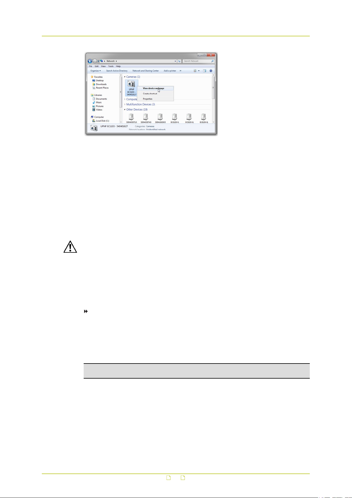
To connect to the camera via UPnP
1 In Windows Explorer, open the Network folder.
Detected devices in the same subnet as the computer are displayed, including Siqura
codecs and cameras with UPnP support.
2 Double-click the camera that you want to connect to,
- or Right-click the camera, and then click View device webpage.
If user accounts have been created for the camera, you are directed to the login page of
the camera (see Log on to the camera).
If no user accounts have been created, the Live View page is opened directly.
16
Get access to the camera
4.4 Log on to the camera
By default, users can freely open the web interface of the camera. They are not required to
log on.
Admin account
Out of the box, there is one user account. This is the built-in "admin" user with password
"1234". The admin can create, modify and delete "Operator" and "User" accounts, as needed.
Before he can start adding accounts, however, he must create a new admin account and set
an admin password. The initial admin account is then no longer available.
CAUTION: MAKE SURE THAT YOU CHANGE THE ADMIN PASSWORD AT THE FIRST LOGIN.
TO KEEP THE ACCOUNT SAFE, CREATE A STRONG, COMPLEX PASSWORD. THIS HELPS TO
PREVENT UNAUTHORISED ACCESS FROM PEOPLE WHO TRY TO USE THE DEFAULT
ACCOUNT.
For your privacy and to better protect your system against security risks, we strongly advise
the use of strong passwords for all functions and network devices. Proper configuration of all
passwords and other security settings is the responsibility of the installer and/or end-user of
the camera.
To create a strong password
● Use at least eight characters
● Do not include your real name, user name, company name, or other personal information
● Do not use complete words that can be found in a dictionary
● Use a random combination of at least two of the following categories: upper case letters,
lower case letters, numbers and special characters
Note: For better protection, especially in high-security systems, we advise you to change
the password at regular intervals.
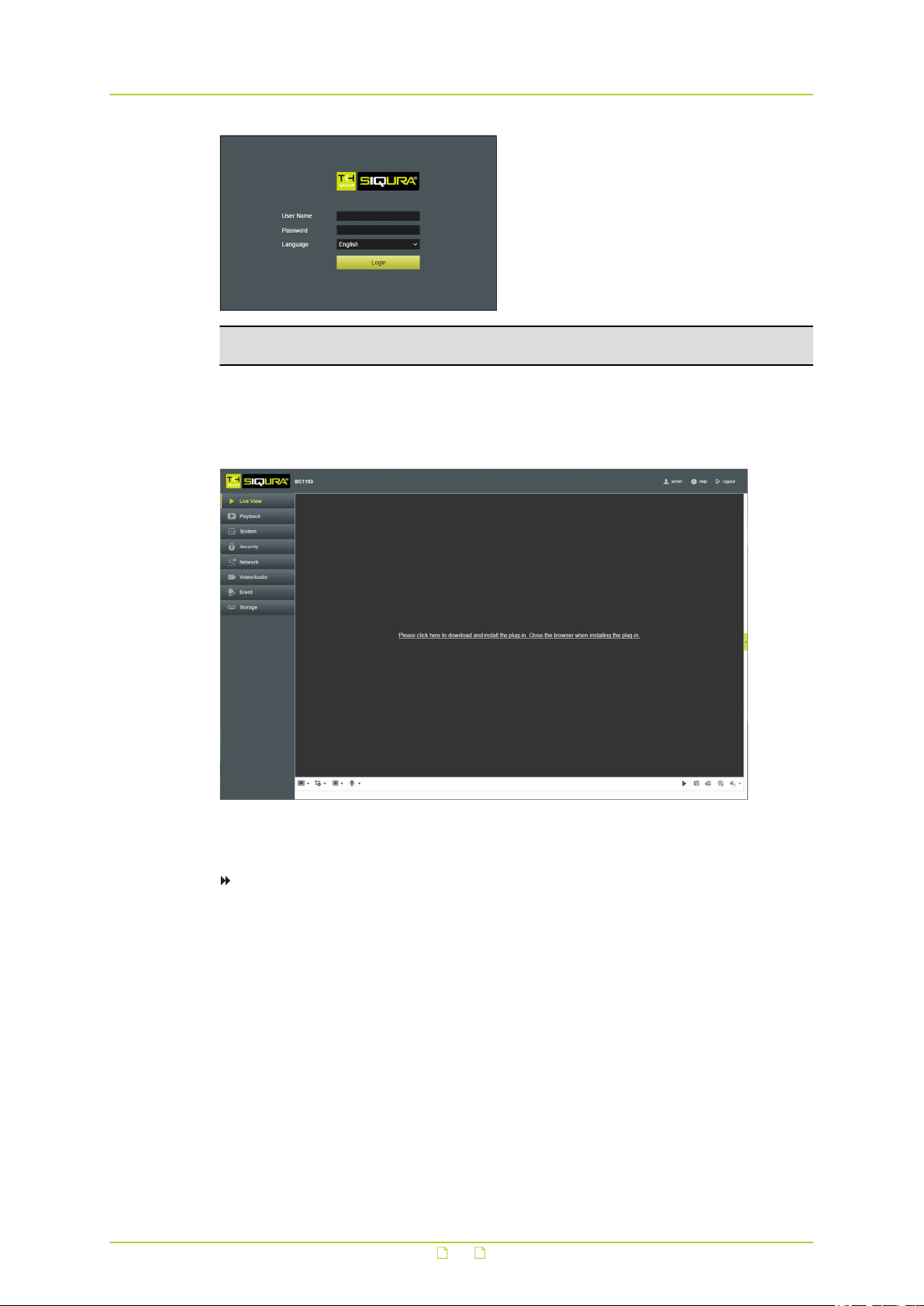
Login box
Once the initial admin account has been replaced, you will encounter a login box when you
connect. You are prompted to supply your user name and password. Only users with a valid
account can log on.
17
Get access to the camera
Note: The IP address of the camera gets locked after seven failed passwords attempts for
the admin and five attempts for the user/operator.
4.5 Install the videoplayer plug-in
For (live) video viewing and operating the camera, a videoplayer plug-in is needed. If the
plug-in is not detected you are prompted to download and install it.
To install the plug-in
1 Click the hyperlink in the webpage of the camera.
2 Save the WebComponents.exe file to your Downloads folder.
3 Close your web browser.
4 Go to your Downloads folder.
5 Double-click WebComponents.exe.
The executable file does not give rise to any security risks. You can install it safely.
6 Follow the installation steps.
7 Open your web browser.
8 Reconnect to the camera.
18
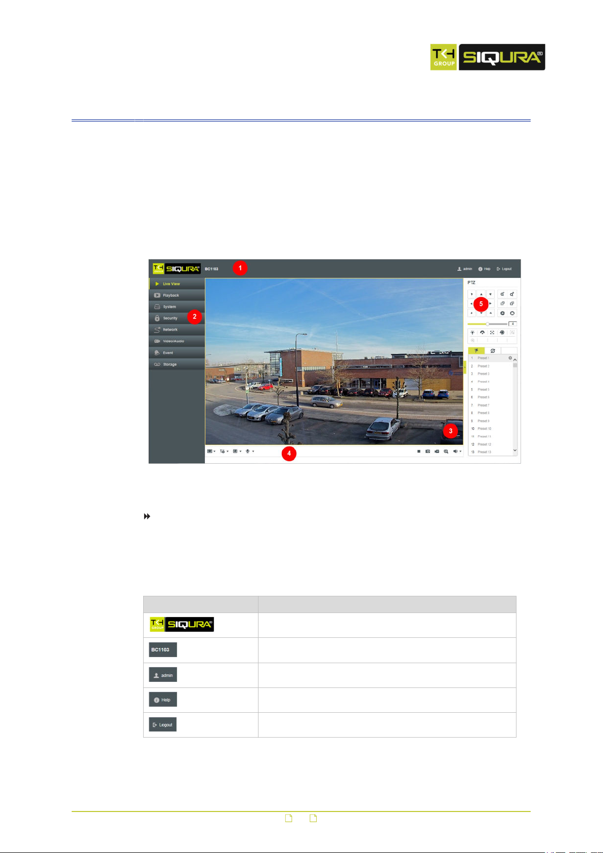
5 Live View
The Live View page is the home page of the web interface. It is shown when you successfully
connect to the camera.
What this page is for
On the Live View page, you can view real-time video, capture images and configure various
video settings. Cameras with PTZ functionality can be controlled from the PTZ panel.
1. Title bar 2. Menu 3. Live View window 4. Toolbar 5. PTZ panel
To show/hide the PTZ panel
● Click the arrow on the right side of of the Live View window.
Title bar
The horizontal bar at the top of the window has the following items.
Item Description
Shows the brand of the camera you are connected to
Shows the camera model name
Shows the user currently logged on to the camera*
Opens the Online Help information
Logs out the current user*
*Not displayed if users do not have to log on
19
Live View
Menu
The vertical menu on the left gives access to the pages of the web interface. Clicking an entry
directly opens the associated page.
Live View window
This area is used to display live video from the connected camera.
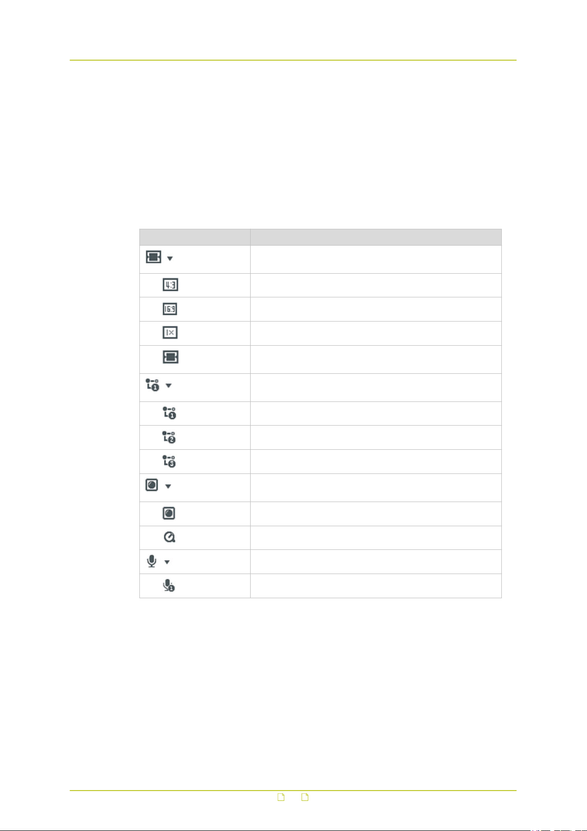
Toolbar
The horizontal bar at the bottom of the page contains two groups of buttons.
Buttons (left side) Description
Opens the Aspect Ratio list. Use the options to set the
relation between the width and height of the video display.
Sets the video aspect ratio to 4:3
Sets the video aspect ratio to 16:9
Sets the original video aspect ratio
Sets the video aspect ratio to Auto mode (self-adaptive
resizing)
Opens the Stream Type list. Use the options to select a
video stream for display in the Live View window.
Selects Stream 1
Selects Stream 2
Selects Stream 3
Opens the video player plug-in list. Use the options to select
a plug-in or live video display.
Selects the Webcomponents plug-in
Selects the QuickTime plug-in
Opens the Two-way Audio list
Turns the microphone on/off
20
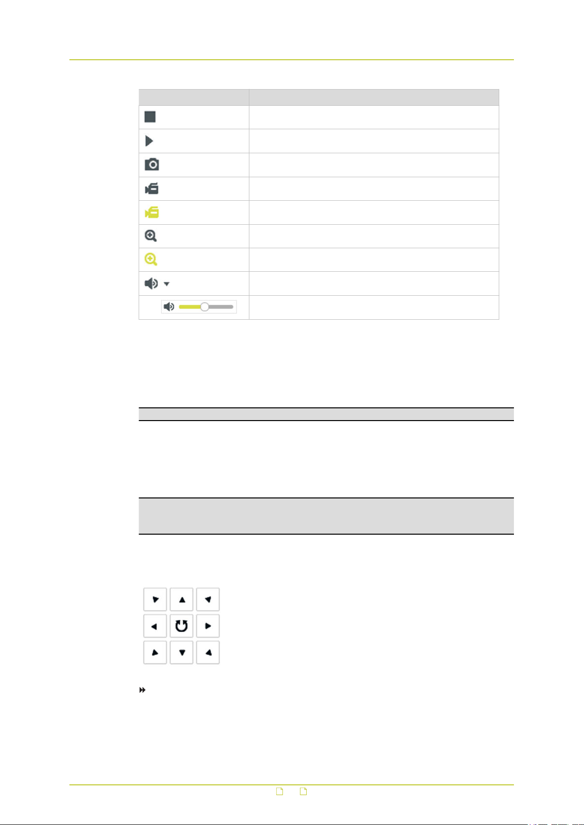
Live View
Buttons (right side) Description
Stops Live View (screen goes blank)
Starts Live View
Captures the image
Starts a recording
Stops a recording
Enables digital zoom (e-PTZ)
Disables digital zoom (e-PTZ)
Opens Audio Volume control
Enables you to control audio volume by dragging the slider
Manual recordings and snapshots
Clicking the Start Recording button starts a manual recording. The recording is saved to the
location set via the Local Configuration tab of the System page. There, you can also set the
storage path for captured snapshots.
Important: To use this function, run your web browser as Administrator.
PTZ Operation
On the Live View page, you can use the PTZ control buttons for pan/tilt/zoom control of the
camera.
Important: To realise PTZ control, the camera connected to the network must support the
PTZ function or a pan/tilt unit must be installed to the camera. Before you realise PTZ
control, make sure that the PTZ parameters (System > RS-485) are correctly configured.
Direction buttons
To pan/tilt the camera
● Click the direction buttons shown above.
- or -
● Drag your mouse pointer across the Live View window.
21
Live View
Note: The direction buttons are not available if your camera model supports lens movement
only.
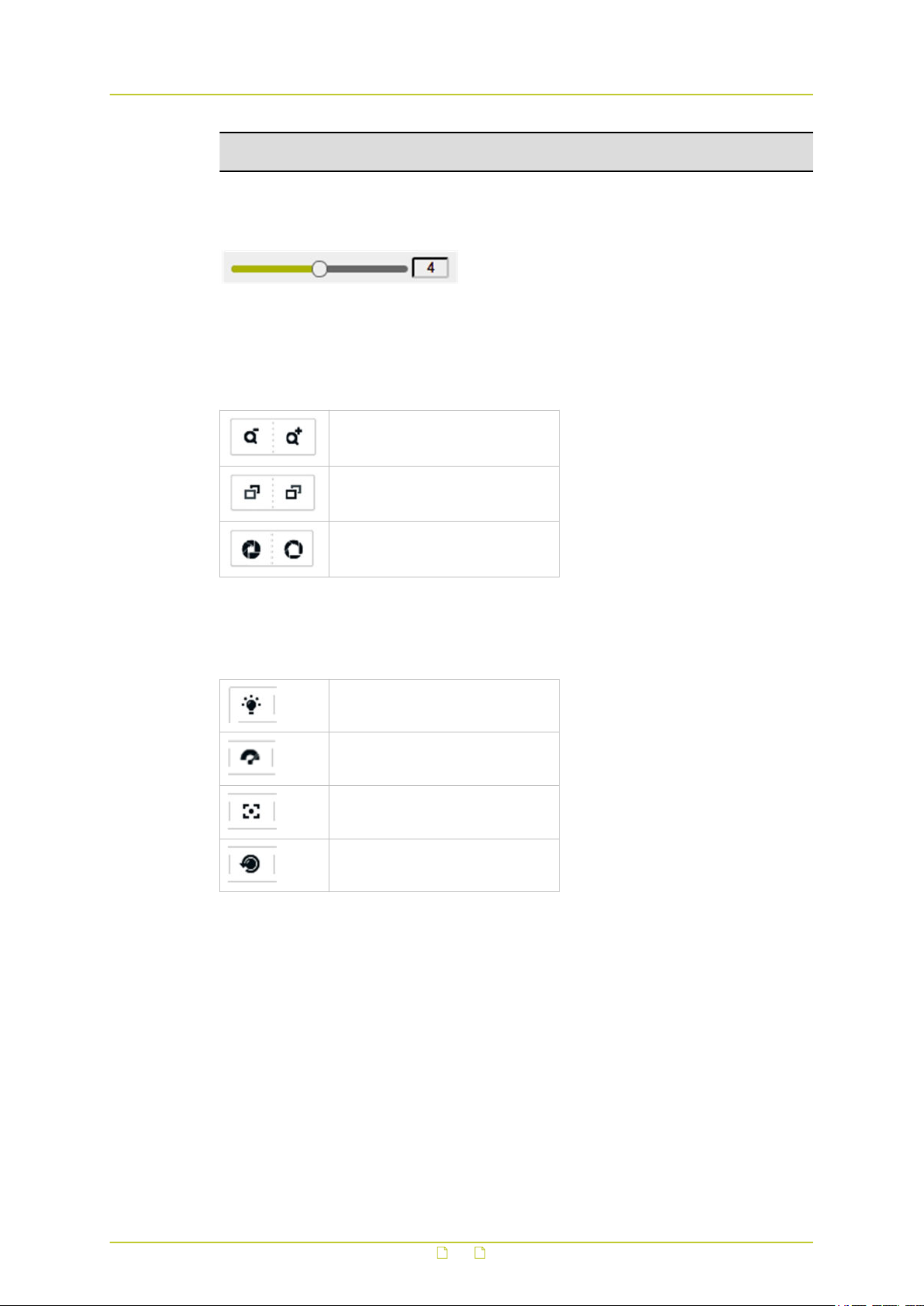
PTZ Speed slider
Use the PTZ Speed slider to adjust the speed of pan/tilt movements. Drag to the right to
increase speed and to the left to decrease speed.
Zoom/Focus/Iris buttons
Zoom out/in
Focus far/near
Iris close/open
Additional buttons
Availability of the following buttons varies per camera model.
Light
Wiper
Auxiliary Focus
Lens Initialisation
Presets
By setting a preset, you can save a camera position to which you want the camera to return
when you call the preset or when an event occurs.
Preset buttons
The following buttons are available for preset management.
22

Live View
Set preset
Call preset
Delete preset
To set a preset
1 In the PTZ control panel, select a preset number from the preset list.
2 Use the PTZ control buttons to move the lens to the desired position.
- Pan the camera to the right or left.
- Tilt the camera up or down.
- Zoom in or out.
- Refocus the lens.
3 Click Set.
To call a preset
1 In the PTZ control panel, select the preset you need.
2 Click Call.
The camera moves to the position stored for this preset.
To delete a preset
1 In the PTZ control panel, select the preset you wish to delete.
2 Click Delete.
Patrols
A patrol is a recorded sequence of presets to be adopted consecutively by the camera when
the patrol is started.
Patrol buttons
The following buttons are available for patrol management.
23

Live View
Set patrol Add preset
Start patrol Delete preset
Stop patrol Move preset down
Delete patrol Move preset up
To create a patrol
1 In the PTZ panel, click the Patrol tab.
2 Select a Patrol Path number.
3 Click Set.
4 Click Add.
5 In the Preset list, select a preset number.
6 In the Speed box, type a value for the patrol speed.
7 In the Time box, type a value for the patrol duration.
8 Repeat steps 4 ~ 7 to add more presets.
9 (Optional) Use the arrow buttons to adjust the order of the presets.
10 Click OK.
To start a patrol
1 In the PTZ pane, click the Patrol tab.
2 Select the Patrol Path to be started.
3 Click Start.
To stop a patrol
1 In the PTZ pane, click the Patrol tab.
2 Select the Patrol Path to be stopped.
3 Click Stop.
To delete a patrol
1 In the PTZ pane, click the Patrol tab.
2 Select the Patrol Path to be deleted.
3 Click Delete.
24
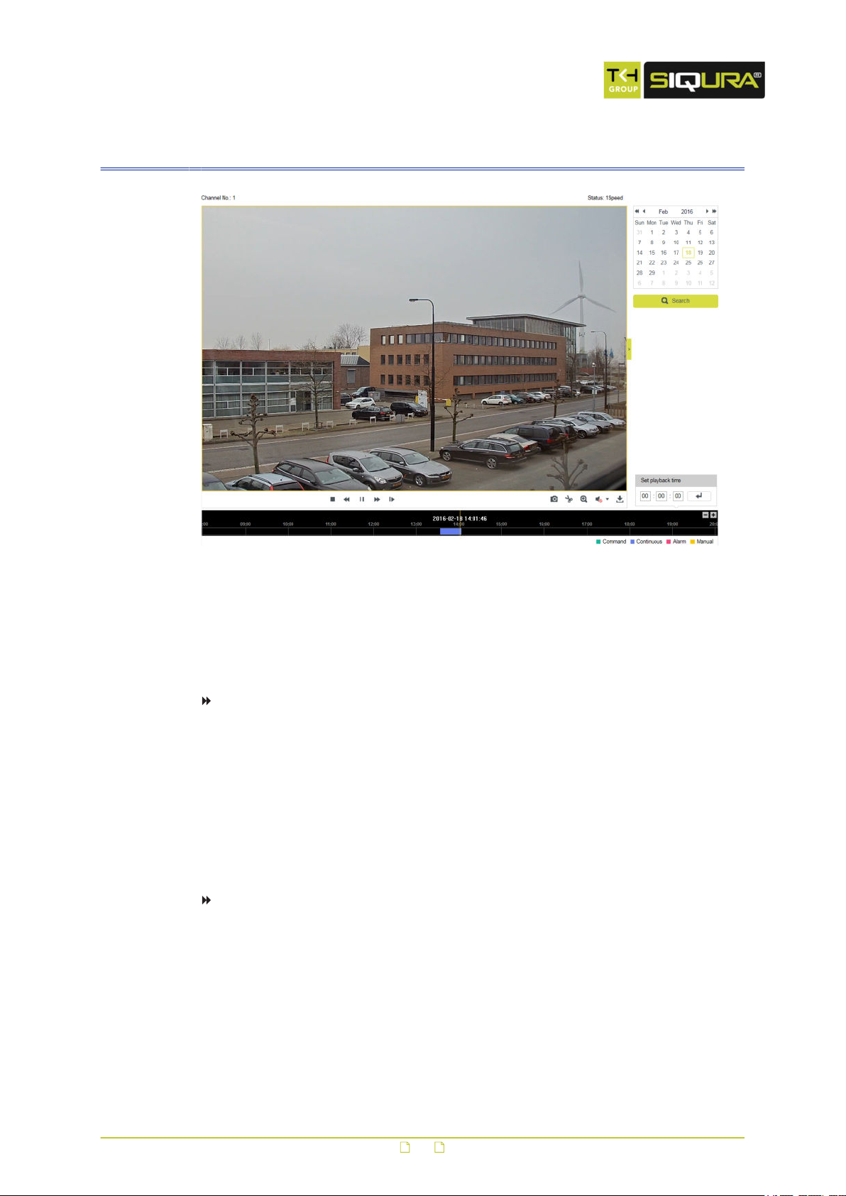
6 Playback
What this page is for
On the Playback page, you can view recorded video stored on a network disk or on the SD
card.
To search for recorded video
1 On the Playback page, go to the calender on the right.
2 Select the date you need.
3 Click Search.
Video recordings for this date - if any - appear in the Time line at the bottom of the
page.
Recording types - Command, Continuous, Alarm, and Manual - can be distinguished by
their colour.
The progress pointer is positioned at the start of the first recording.
To locate a specific playback point
● In Set playback time, type the exact time, and then click Enter.
- or -
● Drag the Time line to the left or right, relative to the pointer.
You can click the "-" and "+" button to zoom the Time line.
Video playback
For video playback, use the following buttons in the Playback toolbar.
25
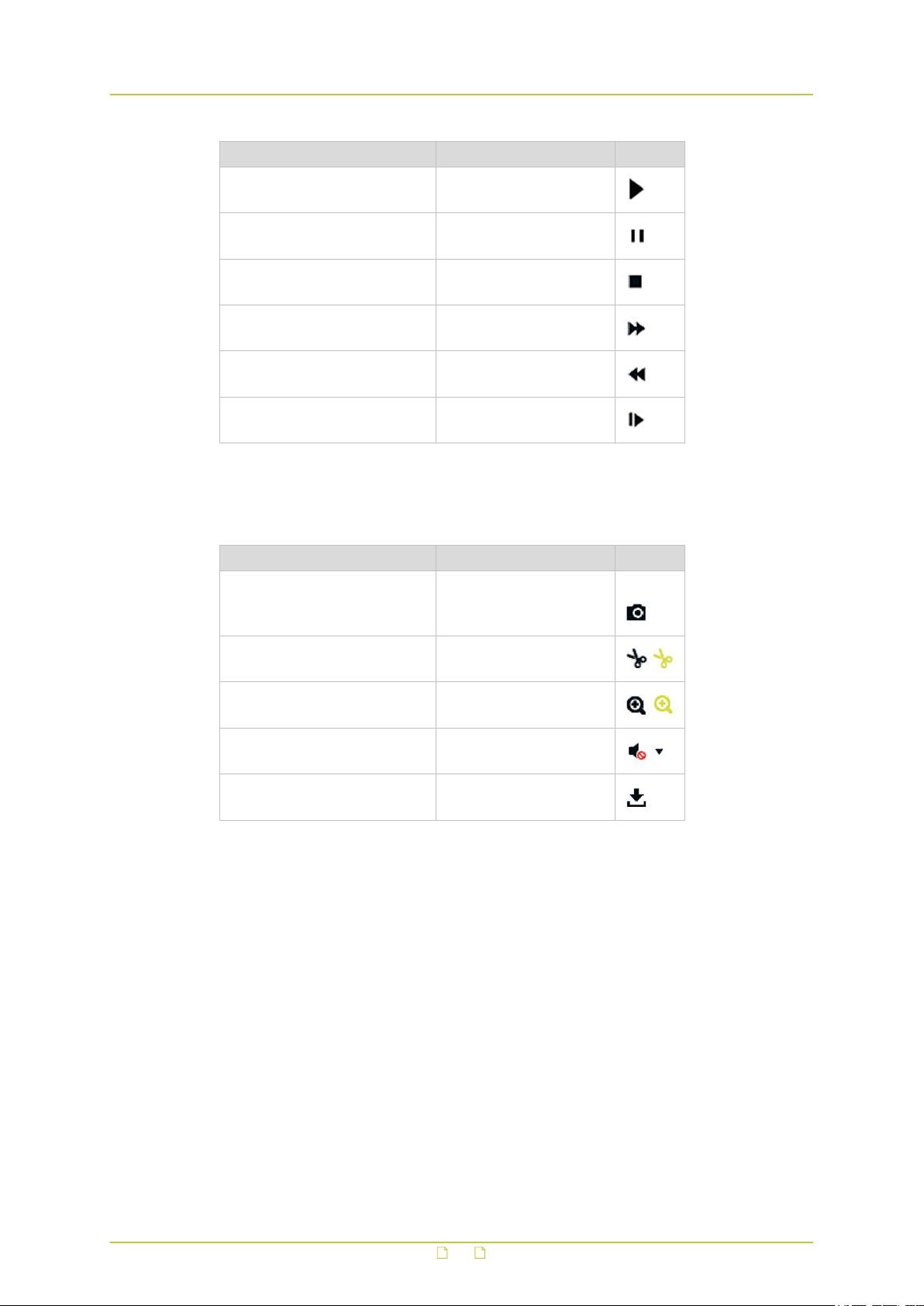
Playback
Task Action Button
To start playback Click Start
To pause playback Click Pause
To stop playback Click Stop
To accelerate playback speed Click Fast forward
To reduce playback speed Click Slow forward
To advance one frame Click Single frame
Additional functions
The buttons below are located on the right side of the toolbar.
Task Action Button
1,
To capture a snapshot Click Capture
To create a video clip
To use digital zoom (e-PTZ)
To control audio volume Click Audio On / Mute
To download a file Click Download
Click Start/Stop
clipping
Click Enable/Disable ePTZ
26
7 System
The System page is the central place for viewing and configuring device and firmware related
information and settings. On the various tabs, you can adjust the time settings, reboot the
camera, restore the default settings, upgrade the firmware, view logs, and configure RS-485
and local settings.
In This Chapter
7.1 Basic Information..................................................................................................27
7.2 Time Settings....................................................................................................... 28
7.3 Upgrade & Maintenance......................................................................................... 29
7.4 RS-485................................................................................................................31
7.5 Log..................................................................................................................... 32
7.6 Local Configuration............................................................................................... 33
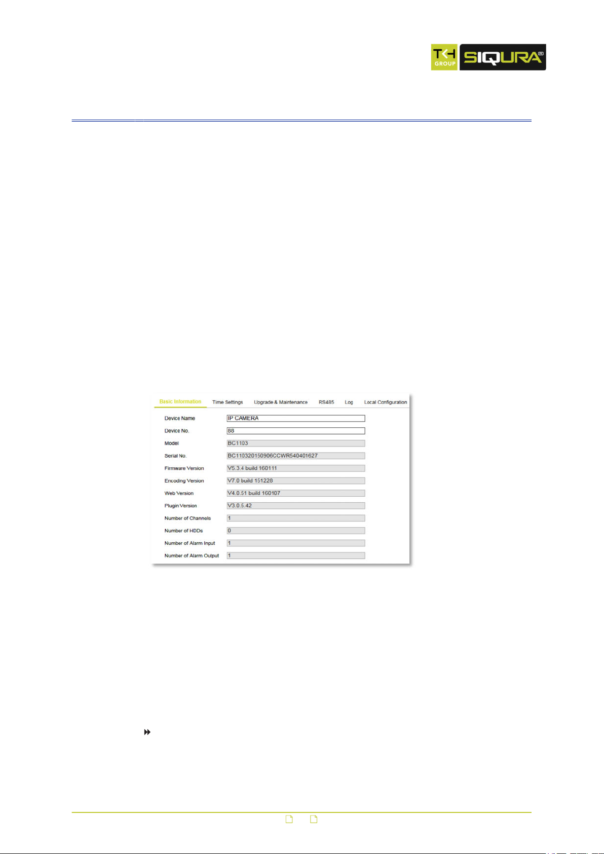
7.1 Basic Information
System > Basic Information
What this tab is for
The Basic Information tab gives general information about the camera. It is made up of
editable and non-editable content.
Identification
For easier identification of the camera on the network, assign a device name and device
number to the camera.
To assign a device name and device number
1 In Device Name, type a (user-friendly) name for the camera.
27
System
2 In Device No., type the camera number.
3 Click Save.
Reference information
The non-editable content on this tab serves as reference information for maintenance or
future configuration of the camera.
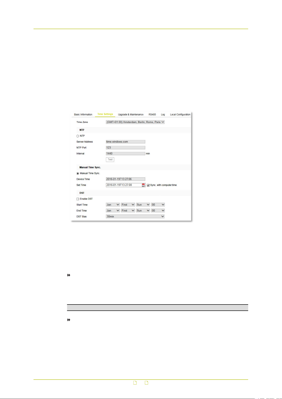
7.2 Time Settings
System > Time Settings
What this tab is for
On the Time Settings tab, you can set the device date and time manually or use an NTP
server. You can also configure the Daylight Saving Time (DST) settings here.
To set the time zone
1 Click to open the Time Zone list.
2 Select the location of the camera.
3 Click Save.
Note: The Time Zone list is not available if Sync. with computer time is selected.
To synchronise the system time with a Network Time Protocol (NTP) server
1 In the NTP section,click NTP.
2 In Server Address, type the IP address of the NTP server.
3 In NTP Port, type the port number of the NTP server.
4 In Interval, type the time interval (in minutes) between the consecutive time service
queries.
28
System
5 Click Test.
The connection to the time server is tested.
6 If your settings are correct, click Save.
Note: If the camera is connected to a public network, use an NTP server that has a time
synchronisation function, such as the server at 224.0.1.1. If the camera is set up in a
customised network, NTP software can be used to establish an NTP server for time
synchronisation.
To set the system time manually
1 In the Manual Time Sync section, select Manual Time Sync.
2 In Set Time, click the Calender/Clock icon.
3 Use the calender and the Time list to set the system date and time.
4 Click OK to confirm your settings.
5 (Optional) As an alternative to steps 2-4, you can select Sync. with computer time.
This synchronises the camera system time with the time of your computer.
6 Click Save.
To enable DST
1 In the DST section, select Enable DST.
2 In the Start Time and End Time lists, select the appropriate start and end details.
3 In the DST Bias list, select the offset.
This is the amount of time you need to subtract from or add to Coordinated Universal
time (UTC) to get the current time for the location of the camera.
4 Click Save.
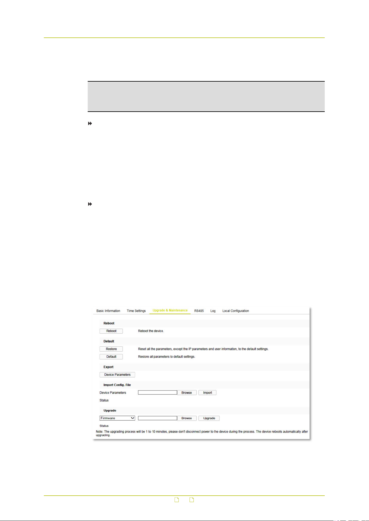
7.3 Upgrade & Maintenance
System > Upgrade & Maintenance
29

System
What this tab is for
Use the Upgrade & Maintenance tab for the following tasks:
● Reboot the camera
● Restore the factory-default camera settings,
● Export/Import a camera configuration file
● Upgrade the camera firmware
Reboot the camera
If there are connectivity problems or if an error occurs, reboot the camera. A reboot does not
affect the settings of the camera.
To reboot the camera
1 Click Reboot.
2 Click OK to confirm.
The webpage is unresponsive while the camera is rebooting.
Restore default settings
With the options in the Default section, you can restore the camera settings to their original
factory-default values. Depending on the option you select, the reset includes or excludes the
current network settings and user information.
To restore the default settings
● Click Restore to reset all settings with the exception of the network settings and the user
information.
- or -
● Click Default to perform a complete reset including the network settings and user
information.
Warning: Clicking Default can make the camera unreachable for in-band communications.
In that case you can only get access to the web interface by (temporarily) moving a PC to
the factory-default subnet of the camera.
Use a configuration file
If you want to apply the same settings to a batch of cameras, use a configuration file to
simplify the process. You configure a camera with the required settings, export the settings in
a configuration file and import this file on the other cameras.
To export a configuration file
1 Click Device Parameters.
2 Browse to the folder where you want to store the file.
3 Specify a file name.
4 Click Save.
To import a configuration file
1 In the Import Config. File section, click Browse.
2 Browse to the folder where the file is stored.
3 Select the file.
4 Click Open.
30
 Loading...