

Siqura 1210 TRA-TRB, 1240 TRX, 1200 TRX, 1250 TRA-TRB User Manual
© Siqura 2017
Version 021403-2f
ADS1200 (MW10)
ADS 1200
Audio, data and contact closure multiplexers for fiber-optic links
USER MANUAL
1. General description
ADS 1200 systems offer combined full duplex
transmission of data, audio and contact closure
signals, all independent, over one or two multimode or
single-mode optical fibers (TRA/TRB or TRX
respectively, see figures 1a, 1b). For technical
specifications, consult section 5.
Two 4-wire audio channels and two contact closure
channels are available on the topmost pair of modular
connectors (port 1 and port 2). The data section
comprises two RS-485/RS-422 (Manchester and
biphase compatible) and two RS-232 channels, on the
two lower modular connectors.
Internal dip switches control the configuration (2/4
wiring and type; default is 4-wire RS-485) of the RS4xx interfaces. If necessary, the RS-485 interfaces can
be adapted to use biasing; by default, the data
interfaces are transparent. By removing a jumper and
output rewiring, port D1 can be used for digital
current loop. Audio input impedance is jumper
selectable. The contact closure outputs are potentialfree and open on synchronisation failure.
LEDs indicate power and local as well as remote sync
status (see section 2), and also monitor data I/O.
The 7TE modules will slot into the backplanes of
TKH Security’s MC 10 or MC 11 power supply
cabinets. Stand-alone models (/SA option, see
supplementary manual) needs an external 12 Vdc
power supply.
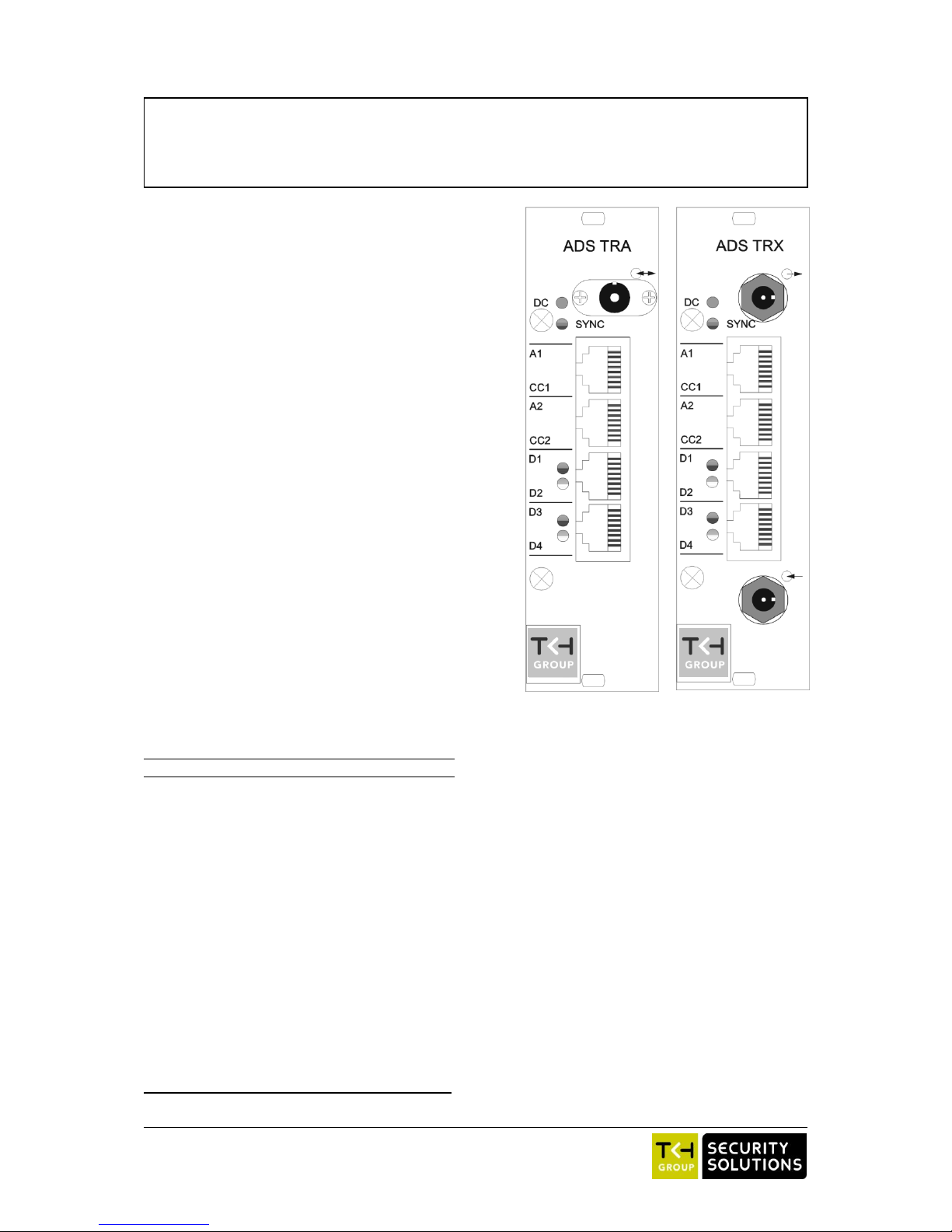
2. Connectors and indicators
Indication
Meaning
o
(ST or FC connector)
Optical input (two-fiber units)
o
(ST or FC connector)
Optical output (two-fiber units)
o
(ST or FC connector)
Optical input/output
(single-fiber units)
Modular sockets:
A1/CC1
audio1, contact closure 1
A2/CC2
audio2, contact closure 2
D1/D2 (D1: see text)
RS-485 (422), RS-232
D3/D4
RS-485 (422), RS-232
System status LEDs:
*SYNC
(red)
No sync from optical in,
or no internal sync
(orange)
No sync @ remote optical in
(green)
All sync OK
*DC
(green)
DC power good
Data status LEDs:
*D1, *D3
red/green
RS-485 input to D1,3 = 1/0
off
high-Z
*D2, *D4
green/off
RS-232 input to D2,4 =1/0
Table 1. Connectors and indications on the ADS 1200 front
panel (the modular sockets take RJ-45 plugs)
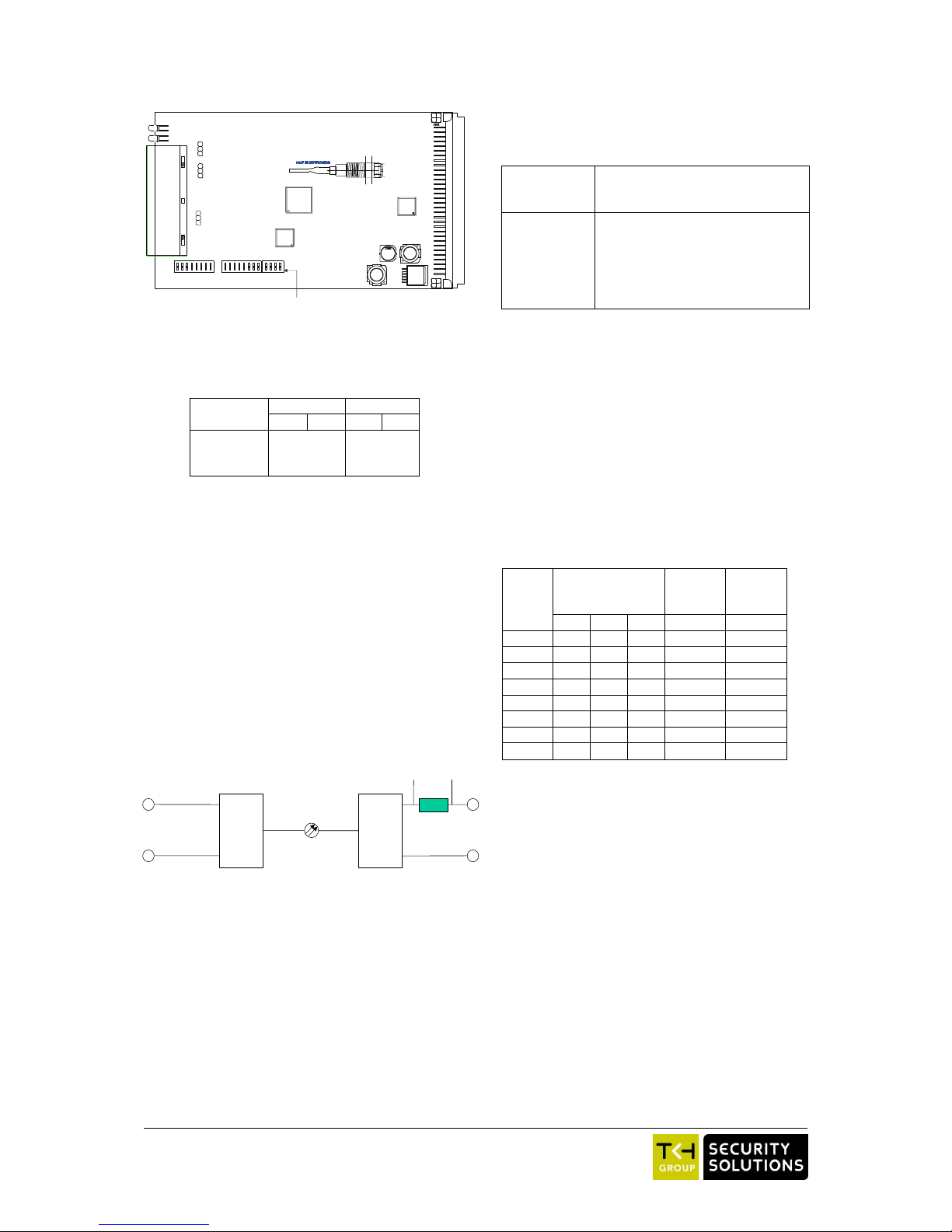
3. Configuration and installation
3a) Configuration
Interface selection and configuration are performed
using switches and jumpers on the circuit boards of
the ADS 1200 units. To access these elements, each
unit must be opened by taking out the two front
panel Phillips head screws indicated in figure 1 and
partially sliding out the circuit board (shown in
figure 2).
An ADS 1200 data board has two 8-fold (S1, S2)
and one 4-fold (S3) dip switch blocks. The first
switch of each block and the ON positions are also
indicated in figure 2.
The jumper-pin groups A and B control audio input
impedance of A1 and A2, respectively; jumper C
regulates the current loop impedance of one of the
RS-485 data outputs (see below).
Data interface selection: the 4 dip switches in bank
S3 determine the RS-4xx interface type available
on ports D1 and D3 as per table 2.
Figure 1. ADS front panels: TRA (left, similar to
TRB, one-fiber), and TRX (right, two-fibers)
2
Interface
type
port D1
port D3
S3-1
S3-2
S3-3
S3-4
RS-485 2-w.
0 0 0
0
RS-485 4-w.
0 1 0
1
RS-422
1 0 1
0
Table 2. Choosing RS-485 interface types
using dip switch bank S3
Two-wire RS-485 mode uses the input terminals for
I/O. In older ADS/VAD units, for two-wire mode the
+ in and + out needed to be combined, as well as - in
and - out; old and new units can be used together with
the old-style cable layout.
Current loop output: The RS-485 output impedance
of port D1 can be made suitable for digital 20 mA
current loop ('TTY') applications by pulling a 2-pin
jumper (C2-3) from the board, thus inserting a resistor
into the non-inverting data line. The jumper may be
put on pins C1-2 to save it. Current loop I/O should
use only non-inverting lines and signal ground (see
figure 3); the interface type should be set to RS-485
(4-w). Input signal voltage on A-GND (IN+-GND)
should be at least 4V.
RS-485 line biasing: In most cases, the RS-485 data
interface works with the default settings. If, however,
data line biasing is called for by other equipment
connected to the ADS 1200, biasing impedances may
need to be applied and dwell times set. With the other
dip switches configured for RS-485 mode, the
eightfold switch banks S1 (for interface D1) and S2
(for interface D3) on the ADS 1200 circuit boards
(figure 2) control attachment of two bias impedance
resistors to both input and inverting input (table 3
below).
Switch
bank S1 for D1
bank S2 for D3
Function (RS-485 mode set)
1-3
dwell time select, see table 4
4 ON
inverting input tied to +5V over 390
5 ON
inverting input tied to +5V over 10 k
6 ON
line termination 120 (default = off)
7 ON
input tied to GND over 10 k
8 ON
input tied to GND over 390
Table 3. Choosing bias resistances, dwell times and line
termination for interfaces D1 and D3
Note that the 'soft zero' biasing adaptation method
used ties the inverting ('negative') input to the
higher voltage, while the biasing resistor of the
normal input is tied to signal ground. This provides
a well-defined bus state when no driver is active.
The first three dip switches of the banks S1 and S2
on the circuit boards (figure 3) are used to
configure the tristate-sensing/dwell timing of
interface D1 and D3, respectively, if biasing of
RS-485 lines is used, to help indicate the
conclusion of transmission (table 3). Dwell time is
approximately 10*bit length or slightly longer.
Setting
no.
Switch
bank S1 for D1
bank S2 for D3
Dwell
time
(±7%)
Data
rate
(bit/s)
1 2 3
0
OFF
OFF
OFF * 0-max
1
OFF
OFF
ON
**
0-max
2
OFF
ON
OFF
0.17 ms
64000
3
OFF
ON
ON
0.34 ms
38400
4
ON
OFF
OFF
0.67 ms
19200
5
ON
OFF
ON
1.35 ms
9600
6
ON
ON
OFF
2.68 ms
4800
7
ON
ON
ON
5.38 ms
2400
*) default, hardware tri-state detect (1V differential sense,
not to be used together with line-biasing)
**) logic high in the data directly drives the output enable
(i.e. no delay). This setting is especially suitable for
very low data rates.
Table 4. Dip switch settings for unbiased and biased
RS-485 interfacing. Settings 1-7 all need bias resistors
to define zero.
Depending on the actual data rate, switches 1-3 of
block S1 and S2 should then be set as per table 4
(read the notes below). Default is all three switches
off, i.e. hardware tristate sensing.
Notes on dwell times:
- When in doubt about which of two dwell times to
select, use the longer of the two.
- Settings 1-7 only work if the lines are biased to a
‘soft zero’.
- The serial receiver dwell timing circuitry (re)starts
a timer on the rising edges of input data from the
copper side, at the same time sending an output
Figure 3. Current loop connections
U603
11
ON
S1
S2 S3
1
2
3
1
2
3
1
2
3
A
B
C
ADS TRX 650 2033 3
WWJJ
1
Figure 2. ADS TRA/B printed circuit board; details left out
for clarity. Take care not to damage the optical fiber
floating above the board.
GND
B (IN-)
A (IN+)
GND
B (OUT-)
A (OUT+)
220 ohm,
internal
jumper removed
 Loading...