

Sipura Technology SPA2002-ER - Earthlink Truevoice Phone Adpt, SPA-2000, SPA-1000, SPA-3000 User Manual
Page 1

Sipura Technology, Inc.
SPA User Guide
July 2004
© 2003 - 2004 Sipura Technology, Inc Proprietary (See Copyright Notice on Page 2)
1
Page 2

Disclaimer – Please Read:
This document contains implementation examples and techniques using Sipura
Technology, Inc. and, in som e instances, other company’s techno logy and products
and is a recommendation only and does not constitute any legal arrangement
between Sipura Technology, Inc. and the reader, either written or implied. The
conclusions reached and recommendations and statements made are based on
generic network , service and application requir ements and should be r egarded as a
guide to assist you in forming your own opinions and decision regarding your
particular situation. As well, Sipura Technology reserves the right to change the
features and functionalities for products described in this document at any time.
These changes may involve changes to the described solutions over time.
Use of Proprietary Information and Copyright Notice:
This document contains proprietary information that is to be used only by Sipura
Technology custom ers. Any unau thorized dis closure, copying, dis tribution, or use of
this information is prohibited.
© 2003 - 2004 Sipura Technology, Inc Proprietary (See Copyright Notice on Page 2)
2
Page 3

Sipura Technology, Inc.
SPA User Guide
Table of Contents
1. Product Description ....................................................................................................................... 6
1.1. SPA Hardware Overview...................................................................................................... 6
2. Installation Overview ..................................................................................................................... 7
3. Software Configuration.................................................................................................................. 8
3.1.1.1. Firmware Upgrade................................................................................................................8
3.2. IVR Interface......................................................................................................................... 8
3.3. Web Interface ..................................................................................................................... 11
3.3.1. Web Interface Conventions.......................................................................................................... 11
3.3.2. Administration Privileges.............................................................................................................. 12
3.3.3. Basic and Advanced Views.......................................................................................................... 12
3.3.3.1. Resync URL........................................................................................................................ 12
3.3.3.2. Reboot URL........................................................................................................................ 13
Through the Reboot URL, you can reboot the SPA............................................................................... 13
Note: Upon request, the SPA will reboot only when it is idle..................................................................13
3.4. Configuration Parameters................................................................................................... 13
3.4.1. System Parameters...................................................................................................................... 13
System Configuration................................................................................................................................. 13
Network Configuration................................................................................................................................ 13
3.4.2. Provisioning Parameters.............................................................................................................. 14
3.4.3. Upgrade Parameters.................................................................................................................... 15
3.4.4. Protocol Parameters.....................................................................................................................15
3.4.4.1. Dynamic Payload Types..................................................................................................... 17
3.4.4.2. SDP Audio Codec Names................................................................................................... 18
3.4.4.3. NAT Support....................................................................................................................... 18
3.4.5. Line 1 and Line 2 Parameters ...................................................................................................... 19
3.4.5.1. User Account Information................................................................................................... 19
3.4.5.2. Supplementary Services Enablement................................................................................. 22
3.4.5.3. Audio Settings..................................................................................................................... 23
3.4.5.4. Dial Plan............................................................................................................................. 25
3.4.5.5. Polarity Settings.................................................................................................................. 25
3.4.6. User 1 and User 2 Parameters..................................................................................................... 25
3.4.6.1. Call Forward And Selective Call Forward/Blocking Settings............................................... 26
3.4.6.2. Speed Dial Settings............................................................................................................ 26
3.4.6.3. Supplementary Service Settings......................................................................................... 26
3.4.6.4. Distinctive Ring and Ring Settings...................................................................................... 27
3.4.7. Regional Parameters....................................................................................................................28
3.4.7.1. Call Progress Tones........................................................................................................... 28
3.4.7.2. Ring and CWT Cadence..................................................................................................... 29
3.4.7.3. Control Timer Values (sec)................................................................................................. 30
3.4.7.4. Vertical Service Code Assignment......................................................................................31
3.4.7.5. Outbound Call Codec Selection Codes: ............................................................................. 34
3.4.7.6. Miscellaneous Parameters.................................................................................................. 34
3.5. Call Statistics Reporting...................................................................................................... 36
4. SPA-3000 Configuration.............................................................................................................. 38
4.1. Overview............................................................................................................................. 38
4.2. SPA-3000 Voice Configur ation Organization ..................................................................... 39
4.2.1. FXS Interface............................................................................................................................... 40
4.2.2. FXO Interface............................................................................................................................... 41
4.2.3. VoIP Interfaces............................................................................................................................. 42
4.2.4. Call Types.................................................................................................................................... 42
4.2.5. Determining the Availability of the PSTN line............................................................................... 43
4.3. Gateway Call Restriction by Dial Plan................................................................................ 43
© 2003 - 2004 Sipura Technology, Inc Proprietary (See Copyright Notice on Page 2)
3
Page 4

4.4. Authentication Methods ...................................................................................................... 44
4.5. VoIP-To-PSTN Calls (Call Type #4)................................................................................... 46
4.5.1. One-Stage Dialing ........................................................................................................................ 46
4.5.2. Two-Stage Dialing........................................................................................................................ 47
4.6. PSTN-To-VoIP Calls (C al l Type #3)................................................................................... 48
4.7. Terminating Gateway Calls................................................................................................. 50
4.8. Line 1 VoIP Outbound Call Routing (Call Type #7)............................................................ 51
4.9. Line 1 VoIP Fallback to PSTN............................................................................................ 52
4.10. VoIP-To-PSTN Calls Via VoIP1 Interface (Call Type #5)................................................... 52
4.11. PSTN Call Ring Thru Line 1 (Call Type #6)........................................................................ 53
4.12. Symmetric RTP...................................................................................................................54
4.13. Configuration Examples and Call Scenarios...................................................................... 54
4.13.1. Setup VoIP1 and VoIP2 With Separate VoIP Accounts........................................................... 54
4.13.2. Setup VoIP1 and VoIP2 with Same VoIP Account.................................................................. 55
4.13.3. PSTN-To-VoIP Call Without Ringing Thru Line 1.................................................................... 55
4.13.4. PSTN Call Answered By Line 1............................................................................................... 56
4.13.5. VoIP-to-PSTN Call via VoIP2 Interface With PIN Authentication............................................. 57
4.13.6. VoIP-to-PSTN Call via VoIP2 Interface With HTTP Digest Authentication:............................. 57
4.13.7. Line 1 Forward-On-No-Answer to PSTN Gateway.................................................................. 58
4.13.8. Line 1 Forward-All to PSTN Gateway...................................................................................... 59
4.13.9. Line 1 Forward-On-No-Answer to a Particular PSTN Number................................................. 59
4.13.10. Line 1 Forward-Selective to PSTN Gateway or Number ......................................................... 59
4.13.11. From Line 1 Dials 9 to Access PSTN-Gateway for Local Calls................................................ 59
4.13.12. From Line 1 Route 311 and 911 Calls to PSTN-Gateway....................................................... 60
4.14. Summary of SPA-3000 Configuration Parameters............................................................. 60
4.14.1. PSTN Line – Dial Plans........................................................................................................... 60
4.14.2. PSTN Line – VoIP-To-PSTN Gateway Setup.......................................................................... 60
4.14.3. PSTN Line – VoIP Users and Passwords (HTTP Authentication) ........................................... 61
4.14.4. PSTN Line – PSTN-To-VoIP Gateway Setup.......................................................................... 62
4.14.5. PSTN Line – FXO Timer Values – In seconds......................................................................... 63
4.14.6. PSTN Line – PSTN Disconnect Detection............................................................................... 64
4.14.7. PSTN Line – International Control........................................................................................... 65
4.14.8. Line 1 and PSTN Line – Audio Configuration.......................................................................... 66
4.14.9. Line 1 – Gateway Accounts..................................................................................................... 66
4.14.10. Line 1 – VoIP Fallback To PSTN............................................................................................. 67
4.14.11. Line 1 – Dial Plan .................................................................................................................... 67
4.14.12. User1 – Call Forward Settings................................................................................................. 67
4.14.13. User1 – Selective Call Forward Settings................................................................................. 68
4.14.14. Regional – Call Progress Tones .............................................................................................. 68
4.14.15. PSTN User – PSTN-To-VoIP Selective Call Forward Settings................................................ 68
4.14.16. PSTN User – PSTN-To-VoIP Speed Dial Settings.................................................................. 68
4.14.17. PSTN User – PSTN Ring Thru Line 1 Distinctive Ring Settings.............................................. 68
4.14.18. PSTN User – PSTN Ring Thru Line 1 Ring Settings............................................................... 69
4.14.19. Info – PSTN Line Status.......................................................................................................... 69
4.14.20. PSTN/VoIP Caller Commands via DTMF................................................................................ 70
5. User Guidelines........................................................................................................................... 70
5.1. Basic Services .................................................................................................................... 71
5.1.1. Originating a Phone Call.............................................................................................................. 71
5.1.2. Receiving a Phone Call................................................................................................................ 71
5.2. Enhanced Services............................................................................................................. 71
5.2.1. Caller ID....................................................................................................................................... 72
5.2.2. Calling Line Identification Presentation (CLIP)............................................................................. 72
5.2.3. Calling Line Identification Restriction (CLIR) – Caller ID Blocking................................................ 72
5.2.4. Call Waiting.................................................................................................................................. 73
5.2.5. Disable or Cancel Call Waiting..................................................................................................... 73
5.2.6. Call-Waiting with Caller ID............................................................................................................ 75
5.2.7. Voice Mail..................................................................................................................................... 75
5.2.8. Attendant Call Transfer................................................................................................................ 76
5.2.9. Unattended or “Blind” Call Transfer.............................................................................................. 76
© 2003 - 2004 Sipura Technology, Inc Proprietary (See Copyright Notice on Page 2)
4
Page 5

5.2.10. Call Hold.................................................................................................................................. 77
5.2.11. Three-Way Calling................................................................................................................... 77
5.2.12. Three-Way Ad-Hoc Conference Calling.................................................................................. 78
5.2.13. Call Return............................................................................................................................... 78
5.2.14. Automatic Call Back................................................................................................................ 79
5.2.15. Call FWD – Unconditional....................................................................................................... 79
5.2.16. Call FWD – Busy..................................................................................................................... 80
5.2.17. Call FWD - No Answer ............................................................................................................81
5.2.18. Anonymous Call Blocking........................................................................................................ 82
5.2.19. Distinctive / Priority Ringing and Call Waiting Tone................................................................. 82
5.2.20. Speed Calling – Up to Eight (8) Numbers or IP Addresses..................................................... 83
6. Appendix I: Dial Plan .................................................................................................................. 83
© 2003 - 2004 Sipura Technology, Inc Proprietary (See Copyright Notice on Page 2)
5
Page 6
1. Product Description
This guide describes basic use of the Sipura Technology SPA phone adapter – an intelligent lowdensity Voice over IP (VoIP) gateway. The SPA e nables carrier class residentia l and business IP
Telephony services de livered over broadband or high-speed Internet connect ions. By intelligent, we
mean the SPA maintains the states of all the calls it terminates. It is capable of making proper
decisions in reaction to user input events (such as on/off hook or hook flash) with little or no
involvement by a ‘middle-man’ server or media gateway controller.
Examples of proper reactions are: playing dial tone, collecting DTMF digits, comparing them against a
dial plan and term inating a call. With inte lligent endpoints at the e dges of a network , performing the
bulk of the call pr ocessing duties, the dep loyment of a large networ k with thousands of subsc ribers
can scale quickl y without the introduction of complic ated, expensive servers. As desc ribed later in
this section, the S ession Initiation Protocol ( SIP) is a good choice of call s ignaling protocol for the
implementation of such a device in this type of network.
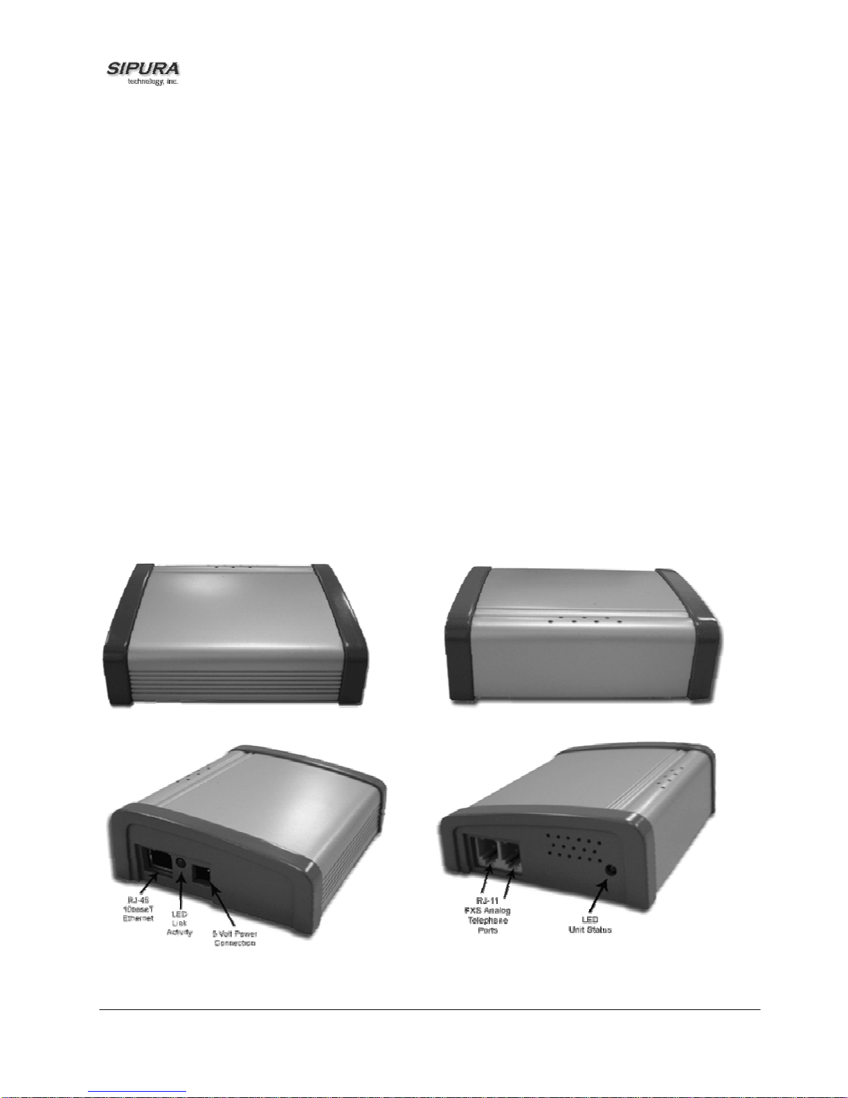
1.1. SPA Hardware Overview
The SPA has one of the smalles t f orm f actor s on the mar k et. It can be ins tall ed in minutes as a tabletop or wall mount CPE device. The images belo w show the SPA-2000. The SPA- 1000 and SPA3000 are similar to size and shape – the only difference being the color of the adapter.
Figures Figure 1, Figur e 2, Figure 3 and Fi gure 4 show the front, re ar, left side and right s ide of the
SPA-2000, respectively.
Figure 1 – SPA-2000 Front
Figure 3 – SPA-2000 Rear
Figure 2 – SPA-2000 Left Side
© 2003 - 2004 Sipura Technology, Inc Proprietary (See Copyright Notice on Page 2)
Figure 4 – SPA-2000 Right Side
6
Page 7

The SPA has the following interfaces for networking, power and visual status indication:
1. Two (2) RJ-11 Type Analog Telephone Jack Interfaces (Figure 4, above):
These interfaces ac cept standard RJ-11 telephone c onnectors. An Analog touc htone telephone or
fax machine m ay be conne cted to either int erf ace. If the s ervic e sup ports o nl y one incoming line, the
analog telephone or f ax machine sho uld be connec ted to port one ( 1) of the SPA. Port one (1) is the
outermost telephone port on the SPA and is labeled “Phone 1.”
The SPA-3000 has an RJ-11 interfac e labeled “Line” which can be used to connect the adapter to a
PSTN analog telephone circuit.
2. One LED for Unit Status (Figure 4, above):
3. One Ethernet 10baseT RJ-45 Jack Interface (
Figure 2, above):
This interface acc epts a standard or crossover Ethernet cable with s tandard RJ-45 connector. For
optimum perf ormanc e, Si p ura Technology recommends that a Category 5 cable or greater b e used in
conjunction with the SPA.
4. One LED for Data Link and Activity (
Figure 2, above):
5. One 5 Volt Power Adapter Interface (
Figure 2, above)
This interface acc epts the SPA power adapter that c ame with the unit. Sipura T echnology does not
support the use of any other power adapters other then the power a dapter that was s hipped with the
SPA unit.
2. Installation Overview
Please check to make sure that you have the following package contents:
1. Sipura Phone Adapter Unit
2. Ethernet Cable
3. RJ-11 Phone Cable (SPA-3000 Only)
4. SPA Quickstart Guide5.
5. Volt Power Adapter
You will also need:
1. One or Two Analog Touch Tone Telephones (or Fax Machine)
2. Access to an IP Network via an Ethernet Connection
3. Access to a PSTN network connection – SPA-3000 only.
Please observe the following steps to install the SPA.From the Left Side of the SPA:1. Insert a
standard RJ-45 Ether ne t c a ble (inc lud ed) into th e LAN port.2. Insert t he power adapter cabl e into th e
5V power adapter cable r eceptacle. Ensure that th e power adapter jack is snugly attached to the
SPA.From the Right Sid e of the SPA:1. Insert a standard RJ-11 te lephone cable into the Phone 1
port.2. Connect the other end of the cable to an analog telephone or fax machine.3. Insert a
standard RJ-11 telephone cable into the Phone 2 port (Optional).4. Connect the other end of the
cable to an analog telephone or fax machine.
Note: Do not conn ect RJ-11 telephone cable from the SPA-1000 or SPA-2000 to th e wall jack to
prevent any chance of connec tion to the circuit switched telco ne twork.You may now insert the plu g
end of the power adapter into a live power outlet which will power up the SPA.
© 2003 - 2004 Sipura Technology, Inc Proprietary (See Copyright Notice on Page 2)
7
Page 8

3. Software Configuration
3.1.1.1. Firmware Upgrade
Firmware Upgrade via PC Utility Program:
From time to time, Sipura Technology will make available a PC executable file that will facilitate the
upgrade of a SPA. In order to upgrade a device via this method, the end user must have
administrative permission (via password protected log-in) to perform this upgrade.
Once the user has obtained the proper firmware upgrade executable, the user simply runs the
program from a file location on their local PC. The PC program walks the user through the upgrade
process via a graphical user interface. Generally, the entire upgrade process should take no more
than five minutes to complete.
Please note: Some end-users who have obtained their SPA directly from a service provider will never
need to manually upgrade their device. Via the remote upgrade process, Sipura Technology provides
capability for the SPA to be maintained from a remote location (e.g. a service provider network
server), using the Internet connection of the end-user as the conduit through which profile updates
and firmware upgrades are performed.
3.2. IVR Interface
Administrators and/or users can chec k (read) and set ( write) basic net work configuration s ettings via
a touchtone telephone connected to one of the RJ-11 phone ports of the SPA.
Please Note:
Service Providers of fering service using the SPA may restrict, protect or turn of f certain aspects of the
unit’s IVR and web configuration capabilities.
The Interactive Voice Res ponse (IVR) capabi lities of the SPA are des igned to give the adminis trator
and/or user basic rea d/write capabilities such that the unit c an attain basic IP network connectivit y
and the more advanced browser-based configuration menu may be accessed.
1. The SPA IVR uses the following conventions: By factory default there is no password and no
password authentication is prompted for all the IVR settings. If administrator password is set,
password authentic ation will be prompted f or certain I VR settings . See 3.4.2 f or detailed inform ation
about administrator password.
To input the password using the phone keypad, the following translation convention applies:
o To input: A, B, C, a, b, c -- press ‘2’
o To input: D, E, F, d, e, f -- press ‘3’
o To input: G, H, I, g, h, i -- press ‘4’
o To input: J, K, L, j, k, l -- press ‘5’
o To input: M, N, O, m, n, o -- press ‘6’
o To input: P, Q, R, S, p, q, r, s -- press ‘7’
o To input: T, U, V, t, u, v -- press ‘8’
o To input: W, X, Y, Z, w, x, y, z -- press ‘9’
o To input all other characters in the administrator password, press ‘0’
© 2003 - 2004 Sipura Technology, Inc Proprietary (See Copyright Notice on Page 2)
8
Page 9

Note: This translation convention only applies to the password input.
For example: to input password “test#@1234” by phone keypad, you need to press the following
sequence of digits: 8378001234.
2. After entering a value, press the # (pound) key to indicate end of input.
o To Save value, press ‘1’
o To Review the value, press ‘2’
o To Re-enter the value, press ‘3’
o To Cancel the value entry and return to the main configuration menu, press ‘
Notes:
o The final ‘#’ key won’t be counted into value.
o Saved settings will take effect when the telephone is hung-up and if necessary, the S PA will
automatically reboot.
3. After one minute of inactivity, the un it times out. T he user will need to re-en ter the configurat ion
menu from the beginning by pressing * * * *.
4. If, while entering a valu e (lik e an IP addr ess) and you d ecid e to exit with out enter ing an y changes ,
you may do so by pressing the * (star) key twice within a half second window of tim e. Otherwise,
the entry of the * (star) key will be treated as a dot (decimal point).
Example: To enter IP addres s, use numbers 0 – 9 on the telephone ke y pad and use the * (star) key
to enter a decimal point.
To enter the following IP address value: 192.168.2.215
A. Use the touchtone key pad to enter: 192*168*2*215#
B. When prompted, enter 1 to save setting to configuration.
C. Hang-up the phone to cause setting to take effect.
- or D. Enter the value of the next setting category to modify . . .
*’ (star)
5. Hang-up the phone to cause all settings to take effect.
SPA Interactive Voice Response (IVR) Menu:
IVR Action IVR Menu Choice Parameter(s) Notes:
Enter IVR Menu
* * * *
Exit IVR Menu
Check DHCP
© 2003 - 2004 Sipura Technology, Inc Proprietary (See Copyright Notice on Page 2)
3948
100
None Ignore SIT or other tones
until you hear, “Sipura
configuration menu.
Please enter option
followed by the pound key
or hang-up to exit.”
None
None IVR will announce if DHCP
in enabled or disabled.
9
Page 10

Enable/Disable DHCP
Check IP Address
Set Static IP Address
Check Network Mask
Set Network Mask
Check Static Gateway IP
Address
101
110
111
120
121
130
Enter 1 to enable
Enter 0 to disable
Requires Password
None IVR will announce the
current IP address of SPA.
Enter IP address
using numbers on
the telephone key
pad. Use the *
(star) key when
entering a decimal
DHCP must be “Disabled”
otherwise you will hear,
“Invalid Option,” if you try
to set this value.
Requires Password
point.
None IVR will announce the
current network mask of
SPA.
Enter value using
numbers on the
telephone key pad.
Use the * (star) key
when entering a
decimal point.
DHCP must be “Disabled”
otherwise you will hear,
“Invalid Option,” if you try
to set this value.
Requires Password
None IVR will announce the
current gateway IP
address of SPA.
Set Static Gateway IP
Address
Check MAC Address
Check Firmware Version
Check Primary DNS
Server Setting
Set Primary DNS Server
131
140
150
160
161
Enter IP address
using numbers on
the telephone key
pad. Use the *
(star) key when
entering a decimal
DHCP must be “Disabled”
otherwise you will hear,
“Invalid Option,” if you try
to set this value.
Requires Password
point.
None IVR will announce the
MAC address of SPA in
hex string format.
None IVR will announce the
version of the firmware
running on the SPA.
None
IVR will announce the
current setting in the
Primary DNS field.
Enter IP address
Requires Password
using numbers on
the telephone key
pad. Use the *
(star) key when
entering a decimal
point.
© 2003 - 2004 Sipura Technology, Inc Proprietary (See Copyright Notice on Page 2)
10
Page 11

Check SPA’s Web Server
Port
170
None
IVR will announce the
port that the web server
is listening on. (Default is
80)
Enable/Di sable Web
Server of SPA
Manual Reboot of Unit
7932
732668
Enter 1 to enable
Enter 0 to disable
None After you hear “Option
Requires Password
Successful,” hang-up. Unit
will reboot automatically.
User Factory Reset of Unit
WARNING:
ALL “User-Changeable” NON-
DEFAULT SETTINGS WILL BE
LOST!
This might include network and
service provider data.
877778
Enter 1 to confirm
Enter *(star) to
cancel operation
SPA will prompt for
confirmation. After
confirming, you will hear
“Option Successful.” Hang-
up. Unit will reboot and all
“User Changeable”
configuration param eter s
will be reset to factory
default values.
Factory Reset of Unit
WARNING:
ALL NON-DEFAULT SETTINGS
WILL BE LOST!
This includes network and
service provider data.
73738
Enter 1 to confirm
Enter * (star) to
cancel operation
SPA will prompt for
confirmation. After
confirming, you will hear
“Option Successful.” Hang-
up. Unit will reboot and all
configuration param eter s
will be reset to factory
default values.
Note: If the Administrator password is not set or the user is allowed to change it, the items marked
with “Requires Password” will not require a password.
3.3. Web Interface
The SPA provides a built-in web server. C onfigurati on and adm inistration c an be perfor med through
this convenient web interf ac e.
3.3.1. Web Interface Conventions
The SPA uses the following conventions with the web administration capabilities:
o The SPA web adm inistration supports two privil ege levels: Administrator and U ser. To use
the User privilege, simply point a web browser at the IP address of the SPA; to use the
administrator privilege, use URL http://IP_Address_Of_SPA/admin
information about administration privileges.
o Version 1.0 of the SPA supports Internet Explorer 5.5 and above and Netscape 7.0 and
above.
o The web configuration pages can be password protected. See 3.3.2 for more information
about password protect.
o The user name of web Administrator is : admin
o The user name of web User is : user
© 2003 - 2004 Sipura Technology, Inc Proprietary (See Copyright Notice on Page 2)
/. See 3.3.2 for more
11
Page 12

o Note: The user names for both administrator and User are fixed and cannot be changed.
o After making changes to SPA configuration parameters, pressing “Submit All Changes”
button will apply all th e changes and if necessar y, automatically reboot the devi ce. Multiple
changes may be made on multiple page tabs of the web int erf ac e at the s ame time. Pressing
“Submit All Changes” will apply all the modifications.
Important Note: switching between page tabs won’t apply the changes to SPA, The only way
to apply the changes is to press the “Submit All Changes” button.
o If the “Undo All Changes” button is clicked, an y modifications to prof ile parameters on any and
all pages will be reset back to their original values before modification.
NOTE: Pressing the “Undo All Changes” has no effect on the SPA; it will only reset the
values on the web page.
3.3.2. Administration Privileges
The SPA supports t wo levels of adm inistration pr ivileg es: Adm inistrator a nd User, both pr ivileges can
be password protecte d. Im portant note: b y factory default, there ar e n o pass words assigned for b oth
Administrator and User.
The Administrator h as the privil ege to modif y all the web prof ile parameters and can also m odify the
passwords of both Administrator and User. A User only has the pr ivilege to access part of the web
profile parameter s ; the par ameter group that User c an ac ces s is s pec if ie d by the Administrator , which
can only be done through provisioning.
To access the Administrator level privilege, use URL: http://IP_Address_Of_SPA/admin
/. If the
password has been set f or Administrator, the browser will prom pt for authentication. The username
for Administrator is “admin” and cannot be changed.
To access the User lev el privilege, use URL: http://IP_Address_Of_SPA/
. If the password has be en
set for User, the br owser will prompt for User auth entication. The username f or User is “user” and
cannot be changed.
When browsing Adm inistrator pag es, one can s witch to User pri vileges b y click the link “User Login”.
(Note: if User password was set, the br owser wil l prompt for User authenticatio n when you clic k “User
Login” link). On the other side, from the User pages you can switch to Administrator privilege by
clicking the link “Admin Login.” Authentication is needed if Administrator password has been set.
Warning: S witching between the User and Administrator will discard the uncom mitted changes that
have already been made on the web pages.
3.3.3. Basic and Advanced Views
The web configuration interface provides a Basic and an Advanced view from which the various
configuration parameters can be accessed. The SPA Provisioning tab is only visible from the
Advanced Administr ator vie w of the web interf ace.
Warning: Switching between the bas ic and a dv anc ed vie w will d isc ar d the u ncommitted changes that
have already been made on the web pages.
3.3.3.1. Resync URL
Through Resync URL you can force the SPA to do a resync to a profile specified in the URL.
Note: The SPA will resync only when it is idle.
The syntax of Resync URL is:
© 2003 - 2004 Sipura Technology, Inc Proprietary (See Copyright Notice on Page 2)
12
Page 13

http://<spa-ip-addr>/resync?[[protocol://][server-name[:port]]/profile-pathname]
If no parameter follows “/resync?”, the profile rule setting in provisioning is used. See Error!
Reference source not found. for detailed information about profile rule in provisioning
If no protocol is specif ied, TFTP protocol is assumed. Note: O nly TFTP is supported in the current
release.
If no server-name is specified, the host that requests the URL is used as server-name.
If no port specified, default port of the protocol is used – 69 for TFTP.
The profile-path is the path to the new profile to resync with.
For example: http://192.168.2.217/upgrade?tftp://192.168.2.251/spaconf.scf
3.3.3.2. Reboot URL
Through the Reboot URL, you can reboot the SPA.
Note: Upon request, the SPA will reboot only when it is idle.
The Reboot URL is: http://<spa-ip-addr>/admin/reboot
3.4. Configuration Parameters
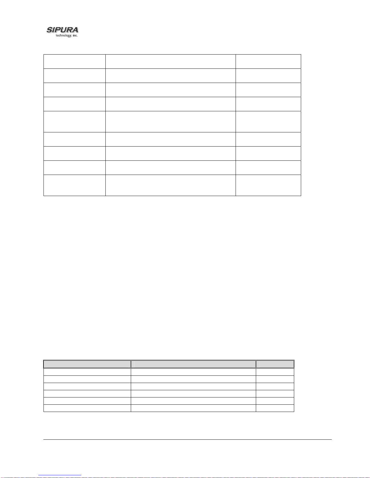
3.4.1. System Parameters
System Configuration
Parameter Name Description Default
Restricted Access
Domains
Enable Web Server Enable/disable web server of SPA
Enable Web Admin
Access
Admin Password The password for administrator
User Password The password for User
Parameter Name Description Default
DHCP Enable/Disable DHCP Yes
Host Name Host Name of SPA
Domain The network domain of SPA
Static IP Static IP address of SPA, which will take effect if DHCP
NetMask The NetMask used by SPA when DHCP is disabled 255.255.255.
Gateway The default gateway used by SPA when DHCP is
Primary DNS DNS server used by SPA in addition to DHCP supplied
Secondary DNS DNS server used by SPA in addition to DHCP supplied
This feature is used when implementing software
customization.
This feature should only be used on firmware version 1.0.9 or later.
Enable/disable Admin pages of web server of SPA
Network Configuration
is disabled
disabled
DNS servers if DHCP is enabled; when DHCP is
disabled, this will be the primary DNS server.
DNS servers if DHCP is enabled; when DHCP is
disabled, this will be the secondary DNS server.
Yes
Yes
0.0.0.0
0
0.0.0.0
0.0.0.0
0.0.0.0
© 2003 - 2004 Sipura Technology, Inc Proprietary (See Copyright Notice on Page 2)
13
Page 14

DNS Query Mode Do parallel or sequential DNS Query Parallel
Syslog Server Specify the Syslog server name and port. This feature
specifies the server for logging SPA system information
and critical events.
Debug Server The debug server name and port. This feature
specifies the server for logging SPA debug information.
The level of detailed output depends on the debug level
parameter setting.
Debug Level The higher the debug level, the more debug
0
information will be generated. Zero (0) means no
debug information will be generat ed.
Primary NTP
IP address or name of primary NTP server.
Server
Secondary NTP
IP address or name of secondary NTP server
Server
Web Server Port TCP port through which the SPA web server will
80
communicate
Notes:
- Parallel DNS query mode: SPA will send the same request to all the DNS servers at the same
time when doing a DNS lookup, the first incoming reply will be accepted by SPA.
- To log SIP messages, Debug Level must be set to at least 2.
- If both Debug Server and Syslog Server are specified, _Syslog messages are also logged to the
Debug Server.
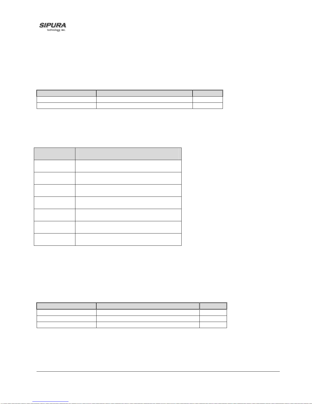
3.4.2. Provisioning Parameters
Provisioning operations are gated by the Provision_Enable parameter.
Parameter Name Description Default
Provision Enable yes
Resync On Reset yes
Resync Random
Delay
Resync Periodic 3600
Resync Error Retry
Delay
Resync From SIP Yes
Resync After Upgrade
Attempt
Resync Trigger 1
Resync Trigger 2
Profile Rule /spa.cfg
Profile Rule B
Profile Rule C
Profile Rule D
Log Resync Request
Msg
Log Resync Success
Msg
2
3600
Yes
See
provisioning
discussion
section
See
provisioning
discussion
© 2003 - 2004 Sipura Technology, Inc Proprietary (See Copyright Notice on Page 2)
14
Page 15

section
Log Resync Failure
Msg
See
provisioning
discussion
section
GPP A thru GPP P empty
GPP SA thru GPP SD empty
Note: In a customized SPA, the profile ru le wou ld po int to a service pr ov id er’s serv er .
3.4.3. Upgrade Parameters
Parameter Name Description Default
Upgrade Enable Yes
Upgrade Error
Retry Delay
Upgrade Rule empty
Log Upgrade
Request Msg
Log Upgrade
Success Msg
Log Upgrade
Failure Msg
Note: In a customized SPA, the upgrade rule would point to a service provider’s server.
3600
See
provisioning
discussion
section
See
provisioning
discussion
section
See
provisioning
discussion
section
3.4.4.
Protocol Parameters
Parameter Name Description Default
Max Forward SIP Max-Forward value. Range: 1 – 255 70
Max Redirection Number of times to allow an INVITE to be
5
redirected by a 3xx response to avoid an
infinite loop.
Note: This parameter currently has no effect: there is
no limit on number of redirection.
Max Auth Maximum number of times a request may be
2
challenged (0-255)
SIP User Agent
Name
User-Agent Header to be used by the unit in
outbound requests. If empty, the header is not
Sipura/
$version
included.
SIP Server Name Server Header to used by the unit in
responses to inbound responses. If empty,
Sipura/
$version
the header is not included.
SIP Accept
Language
Accept-Language Header to be used b y the
unit.
If empty, the header is not included.
© 2003 - 2004 Sipura Technology, Inc Proprietary (See Copyright Notice on Page 2)
15
Page 16

Remove Last Reg Remove last registration before registering a
no
new one if value is different one.
DTMF Relay MIME
Type
Hook Flash MIME
Type
This is the MIME Type to be used in a SIP
INFO message used to signal DTMF event.
This is the MIME Type to be used in a SIP
INFO message used to signal hook flash
application/dtmf-relay
application/hook-flash
event.
Use Compact
Header
If set to yes, the SPA will use compact SIP
headers in outbound SIP messages. If set to
no
no the SPA will use normal SIP headers.
SIP T1 RFC 3261 T1 value (RTT Estimate). Range: 0
.5
– 64 sec
SIP T2 RFC 3261 T2 value (Maximum retransmit
4
interval for non-INVITE requests and INVITE
responses). Range: 0 – 64 sec
SIP T4 RFC 3261 T4 value (Maximum duration a
5
message will remain in the network). Range:
0 – 64 sec
SIP Timer B INVITE time out value. Range: 0 – 64 sec 32
SIP Timer F Non-INVITE time out value. Range: 0 – 64
32
sec
SIP Timer H INVITE final response time out value. Range:
32
0 – 64 sec
SIP Timer D ACK hang around time. Range: 0 – 64 sec 32
SIP Timer J Non-INVITE response hang around time.
32
Range: 0 – 64 sec
INVITE Expires INVITE request Expires header value in sec.
0 = do not include Expires header in INVITE.
Range: 0 – (2
31
– 1)
ReINVITE Expires ReINVITE request Expires header value in
sec. 0 = do not include Expires header in the
request. Range: 0 – (2
31
– 1)
Reg Min Expires Minimum registration expiration time allowed
180
30
1
from the proxy in the Expires header or as a
Contact header parameter. If proxy returns
something less this value, then the minimum
value is used.
Reg Max Expires Maximum registration expiration time allowed
7200
from the proxy in the Min-Expires header. If
value is larger than this, then the maximum
value is used
Reg Retry Intvl Interval to wait before the SPA retries
30
registration again after encountering a failure
condition during last registration
Reg Retry Long
Interval
When Registration fails with a SIP response
code that does no match <Retry Reg RSC>,
1200
the SPA will wait for the delay specified in this
parameter before retrying. If this parameter is
0, the SPA will stop retrying. This value
should be much larger than <Reg Retry Intvl>
which should not be 0.
SIT1 RSC1 SIP response status code to INVITE on which
to play the SIT1 Tone
© 2003 - 2004 Sipura Technology, Inc Proprietary (See Copyright Notice on Page 2)
16
Page 17
SIT2 RSC1 SIP response status code to INVITE on which
to play the SIT2 Tone
SIT3 RSC1 SIP response status code to INVITE on which
to play the SIT3 Tone
SIT4 RSC1 SIP response status code to INVITE on which
to play the SIT4 Tone
Try Backup RSC SIP response status code on which to retry a
backup server for the current request
Retry Reg RSC Interval to wait before the SPA retries
30
registration again after encountering a failure
condition during last registration
RTP Port Min2 Minimum port number for RTP transmission
16384
and reception
RTP Port Max2 Maximum port number for RTP transmission
16482
and reception
RTP Packet Size Packet size in sec. Valid values must be
0.02
multiple of 0.01s. Range: 0.01 – 0.16
RTCP Tx Interval4 Controls the interval (sec) to send out RTCP
0
sender report on an active connection.
Range: 0 – 255 (s)
Notes:
1. Reorder or Busy Tone will be played by default for all unsuccessful response status code
2. <RTP Port Min> and <RTP Port Max> should define a range that contains at least 4 even number
ports, such as 100 – 106
3. If inbound SIP requests contain compact headers, SPA will reuse the same compact headers
when generating th e respons e regardless the set tings of the <Use Compact Hea der> param eter.
If inbound SIP requests contain norm al headers, SPA will substitute th ose headers with compact
headers (if defined by RFC 261) if <Use Compact Header> parameter is set to “yes.”
4. During an active connec tion, the SPA can be pr ogrammed to send out compound RTCP p acket
on the connection. Each compound RTP packet except the last one contains a SR (Sender
Report) and a SDES.(Source Description). The last RTCP packet contains an additional BYE
packet. Each SR ex cept the last one conta ins exac t l y 1 RR (R ec ei ver Report); the last S R car r ies
no RR. The SDES cont ains CNAME, NAME, and TOOL ident ifiers. The CNAME is set to <User
ID>@<Proxy>, NAME is set to <Display Name> ( or “Anonymous” if user block s caller ID), and
TOOL is set to the Verdor/Hardware-platform-software-version (such as Sipura/SPA2000-
1.0.31(b)). The NT P timestam p used in the SR is a snaps hot of the S PA’s loc al ti m e, not the tim e
reported by an NTP server. If the SPA rec eives a RR f rom the peer, it will a ttem pt to com pute the
round trip delay and show it as t he <Cal l Ro un d T r ip Dela y> value (ms) in the Info section of SPA
web page.
3.4.4.1. Dynamic Payload Types
Parameter Name Description Default
NSE Dynamic Payload
AVT Dynamic Payload
G726r16 Dynamic Payload
G726r24 Dynamic Payload
G726r40 Dynamic Payload
G729b Dynamic Payload
1,2
NSE dynamic payload type 100
1,2
AVT dynamic payload type 101
1,2
G726-16 dynamic payload type 98
1,2
G726-24 dynamic payload type 97
1,2
G726-40 dynamic payload type 96
1,2
G729b dynamic payload type 99
Notes:
1. Valid range is 96 – 127
© 2003 - 2004 Sipura Technology, Inc Proprietary (See Copyright Notice on Page 2)
17
Page 18

2. The configured d ynamic payloads are used for outbou nd calls only where the SPA prese nts the
SDP offer. For inbound calls with a SDP offer, SPA will follow the caller’s dynamic payload type
assignments
3.4.4.2. SDP Audio Codec Names
Parameter Name Description Default
NSE Codec Name NSE Codec name used in SDP NSE
AVT Codec Name AVT Codec name used in SDP telephone-event
G711a Codec Name G711a Codec name used in SDP PCMA
G711u Codec Name G711u Codec name used in SDP PCMU
G726r16 Codec Name G726-16 Codec name used in SDP G726-16
G726r24 Codec Name G726-24 Codec name used in SDP G726-24
G726r32 Codec Name G726-32 Codec name used in SDP G726-32
G726r40 Codec Name G726-40 Codec name used in SDP G726-40
G729a Codec Name G729a Codec name used in SDP G729a
G729b Codec Name G729b Codec name used in SDP G729ab
G723 Codec Name G723 Codec name used in SDP G723
Notes:
1. SPA uses the configured codec names in its outbound SDP
2. SPA ignores the codec names in incoming SDP for standard payload types (0 – 95).
3. For dynamic payloa d t ypes, S PA ide ntif ies t he c od ec by the configured codec names. Comparison
is case-insensitive.
3.4.4.3. NAT Support
Parameter Name Description Default
Handle_VIA_received If set to “yes”, the SPA will process the “received”
No
parameter in the VIA header inserted by the server
in a response to any one of its request. Else the
parameter is ignored.
Handle_VIA_rport If set to “yes”, the SPA will process the “rport”
No
parameter in the VIA header inserted by the server
in a response to any one of its request. Else the
parameter is ignored.
Insert VIA received Insert received parameter in VIA header in SIP
No
responses if received from IP and VIA sent-by IP
differ
Insert VIA rport Insert rport parameter in VIA header in SIP
No
responses if received-from port and VIA sent-by
port differ
Substitute VIA addr Use nat-mapped IP:port values in VIA header No
Send Resp To Src Port Send response to the request source port instead of
No
the VIA sent-by port
STUN Server STUN server to contact for NAT mapping discovery
STUN Enable Enable the use of STUN to discover NAT mapping No
STUN Test Enable If enabled with <STUN Enable> = “yes” and a valid
No
<STUN Server>, the SPA will perform a NAT type
discovery operation when first power on by
contacting the configured STUN server. The result
of the discovery will be reported in a Warning
© 2003 - 2004 Sipura Technology, Inc Proprietary (See Copyright Notice on Page 2)
18
Page 19

header in all subsequent REGISTER requests –
“Warning: 399 spa <stun type>”, where <stun type>
is one of the following:
"Unknown NAT Type",
"STUN Server Not Reachable",
"STUN Server Not Responding",
"Open Internet Detected",
"Symmetric Firewall Detected",
"Full Cone NAT Detected",
"Restricted Cone NAT Detected",
"Symmetric NAT Detected";
If the SPA detects Symmetric Nat or Symmetric
Firewall, Nat Mapping will be disabled (th at is , no
substitution of IP address and port with external IP
address an nat-mapped port)
Ext IP External IP address to substitute for the actual IP
address of the unit in all outgoing SIP messages. If
“0.0.0.0” is specified, no IP address substitution is
performed.
Ext RTP Port Min External port mapping of <RTP Port Min>. If this
value is non-zero, the RTP port number in all
outgoing SIP messages is s ubstituted by the
corresponding port value in the externa l RTP port
range.
0.0.0.0
0
NAT Keep Alive Intvl Interval between sending NAT-mapping keep alive
15
message in sec
Notes:
3.4.5. Line 1 and Line 2 Parameters
Per line parameter tags must be appended with [1] or [2] (corresponding to lines 1 or 2) in the
configuration profile. It is omitted below for readability.
3.4.5.1. User Account Information
Parameter Name Description Default
Line Enable Enable this line for service Yes
MOH Server2 The User ID or URL of the auto-answering SAS to
contact for MOH services. Examples: 5000,
1001@music.sipura.com, 66.12.123.15:5061.
Note: When only a user-id is given, the current
proxy or outbound proxy will be contacted as in the
making of a regular outbound call. MOH is disabled
if this parameter is not specified (empty).
SIP Port SIP message listening port and transmission port 5060
Ext SIP Port External port to substitute for the actual SIP port of
the unit in all outgoing SIP messages. If “0” is
specified, no SIP port substitution is performed.
SIP TOS/DiffServ
Value
RTP TOS/DiffServ
Value
TOS/DiffServ field value in UDP IP Pac kets
carrying a SIP Message
TOS/DiffServ field value in UDP IP Pac kets
carrying a RTP data
Empty
0
0x68
0xb8
© 2003 - 2004 Sipura Technology, Inc Proprietary (See Copyright Notice on Page 2)
19
Page 20

SAS Enable3 Enables the FXS Line to act as a Streaming Audio
Source (SAS). If enabled, the line cannot be used
for making outgoing calls. Instead, it auto-answers
incoming calls and streams audio RTP packets to
the calling party.
SAS DLG Refresh
3
Intvl
If non-zero, this is the interval at which SAS sends
out session refresh (SIP re-INVITE) messages to
detect if connection to the caller is still up. If the
caller does not respond to refresh message, SPA
will terminate this call with a SIP BYE message.
The default = 0 (Session refresh disabled)
Range = 0-255 (s)
SAS Inbound RTP
3
Sink
The purpose of this parameter is to work around
devices that do not play inbound RTP if the SAS
line declares itself as a “sendonly” device and tells
the client not to stream out audio. This parameter is
a FQDN or IP address of a RTP sink to be used by
the SPA SAS line in the SDP of its 200 response to
inbound INVITE from a client. It will appear in the c
= line and the port number and, if specified, in the
m = line of the SDP. If this value is not specified or
equal to 0, then c = 0.0.0.0 and a=sendonly will be
used in the SDP to tell the SAS client to not to send
any RTP to this SAS line. If a non-zero value is
specified, then a=sendrecv and the SAS client will
stream audio to the given address. Special case: If
the value is $IP, then the SAS line’s own IP
address is used in the c = line and a=sendrecv. In
that case the SAS client will stream RTP packets to
the SAS line. The default value is [empty].
NAT Mapping Enable Enable the use of externally mapped of IP address
and SIP/RTP ports in SIP messages . The mappin g
may be discovered by any of the supported
methods.
NAT Keep Alive
Enable
If set to “yes”, the configured <NAT Keep Alive
Msg> is sent periodicall y ever y <NAT Keep Al i ve
Intvl> seconds.
NAT Keep Alive Msg Contents of the keep-alive message to be sent to a
given destination periodically to maintain the
current NAT-mapping. It could be an empty string.
If value is $NOTIFY, a NOTIFY message is sent as
keep alive. If value is $REGISTER, a REGISTER
message w/o Contact is sent.
NAT Keep Alive Dest Destination to send NAT keep alive messages to. If
value is $PROXY, it will be sent to the current
proxy or outbound proxy
SIP Debug Option None, 1-line, full, exclude OPTIONS, exclude
REGISTER, exclude NOTIFY, …
Network Jitter Level 4 settings are available: very high, high, medium,
low. This parameter affects how jitter buffer size is
adjusted in the SPA. Jitter buffer size is adjusted
dynamically. The minimum jitter buffer size is 30
ms or (10 ms + current RTP frame size), which
ever is larger, for all jitter level settings. But the
No
0
No
No
$NOTIFY
$PROXY
none
High
© 2003 - 2004 Sipura Technology, Inc Proprietary (See Copyright Notice on Page 2)
20
Page 21

starting jitter buffer size value is larger for higher
jitter levels. This parameter controls the rate at
which to adjust the jitter buffer size to reach the
minimum. If the jitter level is set to high, then the
rate of buffer size decrement is slower (more
conservative), else faster (more aggressive).
SIP 100REL Enable Enable the support or the 100rel SIP extension for
No
reliable transmission of provisional responses (18x)
and the use of PRACK requests.
Blind Attn-Xfer
Enable
If enabled, the SPA performs an attended transfer
operation by terminating the current call leg, and
No
blind transferring the other call leg. If disabled, the
SPA performs an attended transfer by referring the
other call leg to the current call leg while
maintaining both call legs.
Proxy SIP Proxy Server for all outbound requests
Use Outbound Proxy Enable the use of <Outbound Proxy>. If set to “no”,
No
<Outbound Proxy> and <Use OB Proxy in Dialog)
is ignored.
Outbound Proxy SIP Outbound Proxy Server where all outbound
No
requests are sent as the first hop.
Use OB Proxy In
Dialog
Whether to forcer SIP requests to be sent to the
outbound proxy within a dialog. Ignored if <Use
Yes
Outbound Proxy> is “no” or <Outbound Proxy> is
empty
Register Enable periodic registration with the <Proxy>. This
Yes
parameter is ignored if <Proxy> is not specified.
Make Call Without
Reg
Allow making outbound calls without successful
(dynamic) registration by the unit. If “No”, dial tone
No
will not play unless registration is successful
Ans Call Without Reg Allow answering inbound calls without successful
No
(dynamic) registrat ion b y the unit
Register Expires1 Expires value in sec in a REGISTER request. SPA
3600
will periodically renew registration shortly before
the current registration expired. This parameter is
ignored if <Register> is “no”. Range: 0 – (2
31
– 1)
sec
Use DNS SRV Whether to use DNS SRV lookup for Proxy and
No
Outbound Proxy
DNS SRV Auto Prefix If enabled, the SPA will autom atic ally prepend the
No
Proxy or Outbound Proxy name with _sip._udp
when performing a DNS SRV lookup on that name
Proxy Fallback Intvl This parameter sets the delay (sec) after which the
3600
SPA will retry from the highest priority proxy (or
outbound proxy) servers after it has failed over to a
lower priority server. This parameter is useful only if
the primary and backup proxy server list is provided
to the SPA via DNS SRV record lookup on the
server name. (Using multiple DNS A record per
server name does not allow the notion of priority
and so all hosts will be considered at the same
priority and the SPA will not attempt to fall back
after a fail over)
Display Name Subscriber’s display name to appear in caller-id
© 2003 - 2004 Sipura Technology, Inc Proprietary (See Copyright Notice on Page 2)
21
Page 22

User ID Subscriber’s user-id. Usually a E.164 number
Password Subscriber’s a/c password
Auth ID Subscriber’s authentication ID
Use Auth ID If set to “yes”, the pair <Auth ID> and <Password>
No
are used for SIP authentication. Else the pair <User
ID> and <Password> are used.
Mini Certificate Base64 encoded of Mini-Certificate concatenated
Empty
with the 1024-bit public key of the CA signing the
MC of all subscribers in the group.
SRTP Private Key Base64 encoded of the 512-bit private key per
Empty
subscriber for establishment of a secure call.
Notes:
1. If proxy responded to REGISTER with a smaller Expires valu e, the SPA will renew registration
based on this sm aller value inste ad of the configured value. If regist ration failed with an “Expires too
brief” error respons e, the SPA will retry with the value given in the M in-Expires header in the error
response.
2. MOH Notes:
• The remote party mus t indic ate t hat it c an r ece iv e au dio whi le h ol din g MO H t o work. That is the SIP
2xx response from the remote party in reply to the re-INVITE fr om the SPA to put the call on hold
must have the SDP i ndicate a sendrec v or recvo nly attribut e and the r emote des tinatio n address and
port must not be 0
3. SAS Notes:
• Either or both of lines 1 and 2 can be configured as an SAS server.
• Each server can maintain up to 5 simultaneous calls. If the second line on the SPA is disabled, then
the SAS line can maintain up to 10 simultaneous calls. Further incoming calls will receive a busy
signal (SIP 486 Response).
• The streaming audi o source m ust be off-hook for the stream ing to occur. Othe rwise incom ing calls
will get a error response (SIP 503 Response). The SAS line will not ring for incoming calls even if the
attached equipment is on-hook
• If no calls are in sess ion, batter y is removed from tip-and-ring of the FXS port. Some audio so urce
devices have an L ED to indicate the b attery status. T his can be used as a visual indication whether
any audio streaming is in progress.
• IVR can still be used on an SAS line, but th e user needs to f ollo w som e simple s teps: a) Connect a
phone to the port and make sur e the phone is on-hook , b) power on the SPA and c ) pick up handset
and press * * * * to invoke IVR in the usual way. The idea behin d this is that if th e SPA boots up and
finds that the SAS line is on-hook, it will not r emove battery from the line so that IVR ma y be used.
But if the SPA boots up and f inds that the SAS line is off-hook, it will remove batter y from the line
since no audio session is in progress.
• Set up the Proxy and Su bscr iber Inf orm ation for the SAS Li ne as you norm all y would with a re gular
user account.
• Call Forwarding, Call Screening, Call Blocking, DND, and Caller-ID Delivery features are not
available on an SAS line.
3.4.5.2. Supplementary Services Enablement
© 2003 - 2004 Sipura Technology, Inc Proprietary (See Copyright Notice on Page 2)
22
Page 23

The SPA provides nati ve support of a large s et of enhanced or suppl ementary services. Al l of these
services are optional. The parameters listed in the following table are used to enable or disable a
specific supplem entary service. A supplementar y service should be disabled if a) the user has not
subscribed for it, or b) the Ser vice Pro vider inten ds to support s imilar s ervice using oth er means than
relying on the SPA.
Parameter Name Description Default
Call Waiting Serv Enable Call Waiting Service Yes
Block CID Serv Enable Block Caller ID Service Yes
Block ANC Serv Enable Block Anonymous Calls Service Yes
Dist Ring Serv Enable Distinctive Ringing Service Yes
Cfwd All Serv Enable Call Forward All Service Yes
Cfwd Busy Serv Enable Call Forward Busy Servic e Yes
Cfwd No Ans Serv Enable Call Forward No Answer Service Yes
Cfwd Sel Serv Enable Call Forward Selective Service Yes
Cfwd Last Serv Enable Forward Last Call Service Yes
Block Last Serv Enable Block Last Call Service Yes
Accept Last Serv Enable Accept Last Call Service Yes
DND Serv Enable Do Not Disturb Service Yes
CID_Serv Enable Caller ID Service Yes
CWCID Serv Enable Call Waiting Caller ID Service Yes
Call Return Serv Enable Call Return Service Yes
Call Back Serv Enable Call Back Service Yes
Three Way Call Serv1 Enable Three W ay Calling Servic e Yes
Three Way Conf
1,2
Serv
Attn Transfer Serv
Unattn Transfer Serv Enable Unattended (Blind) Call Transfer
Enable Three Way Conference Service Yes
1,2
Enable Attended Call Transfer Service Yes
Yes
Service
MWI Serv3 Enable MWI Service Yes
VMWI Serv Enable VMWI Service (FSK) Yes
Speed Dial Serv Enable Speed Dial Service Yes
Secure Call Serv Enable Secure Call Service Yes
Referral Serv Enable Referral Service. See <Referral
Yes
Services Codes> for more details
Feature Dial Serv Enable Feature Dial Service. See <Feature
Dial Services Codes> for more details
Yes
Notes:
1. Three Way Calling is required for Three Way Conference and Attended Transfer.
2. Three Way Conference is required for Attended Transfer.
3. MWI is available only if a Voice Mail Service is set-up in the deployment.
3.4.5.3. Audio Settings
© 2003 - 2004 Sipura Technology, Inc Proprietary (See Copyright Notice on Page 2)
23
Page 24

Parameter Name Description Default
Preferred Codec Select a preferred codec for all calls. However, the
G711u
actual codec used in a call still depends on the
outcome of the codec negotiation protocol.G711u,
G711a, G726-16, G726-24, G726-32, G726-40,
G729a, G723
Use Pref Codec Only Only use the preferred codec for all calls. The call will
No
fail if the far end does not support this codec.
LBR Codec Enable *** This parameter has been removed. ***
Silence Supp Enable Enable silence suppression so that silent audio
No
frames are not transmitted
Echo Canc Enable Enable the use of echo canceller Yes
Echo Canc Adapt
Enable echo canceller to adapt Yes
Enable
Echo Supp Enable Enable the use of echo suppressor. If <Echo Canc
Yes
Enable> is “no”, this parameter is ignored
G729a Enable1 Enable the use of G729a codec at 8 kbps. Yes
G723 Enable1 Enable the use of G723 codec at 6.3 kbps Yes
G726-16 Enable1 Enable the use of G726 codec at 16 kbps Yes
G726-24 Enable1 Enable the use of G726 codec at 24 kbps Yes
G726-32 Enable1 Enable the use of G726 codec at 32 kbps Yes
G726-40 Enable1 Enable the use of G726 codec at 40 kbps Yes
FAX Passthru Enable *** This parameter has been removed. *** Yes
FAX CED Detect Enable Enable detection of FAX tone. Yes
FAX CNG Detect
Yes
Enable
FAX Passthru Codec Codec to use for fax passthru G711u
FAX Codec Symmetric Force unit to use symmetric codec during FAX
Yes
passthru
FAX Passthru Method Choices: None / NSE / ReINVITE NSE
FAX Process NSE Yes
DTMF Tx Method Method to transmit DTMF signals to the far end:
Auto
Inband = Send DTMF using the audio path; INFO =
Use the SIP INFO method, AVT = Send DTMF as
AVT events; Auto = Use Inband or AVT based on
outcome of codec negotiation
Hook Flash Tx Method Select the method to signal Hook Flash events:
None
• None: do not signal hook flash events
• AVT: use RFC2833 AVT (event=16)
• INFO: use SIP INFO method with the single line
“signal = hf” in the message body. The MIME type for
this message body is taken from the <Hook Flash
MIME Type> paramter
Release Unused Codec Yes
Notes:
1. A codec resource is co nsidered as allocated if it has been included in the SDP codec lis t of an
active call, even though it even tuall y ma y not be the one chos en for the connec tion. So, if the G.72 9a
codec is enabled and included in the codec list, that resource is tied up until the end of the call
whether or not the call ac tually uses G.729a. If the G729a res ource is already allocated and si nce
only one G.729a resource is allowed per SPA, no other low-bit-rate codec may be allocated for
subsequent calls; the only choices are G711a and G711u. On the other hand, two G.723.1/G.726
© 2003 - 2004 Sipura Technology, Inc Proprietary (See Copyright Notice on Page 2)
24
Page 25
resources are availab le per SPA. Therefore it is im portant to disable the use of G.729a in ord er to
guarantee the support of 2 simultaneous G.723/G.726 codec.
3.4.5.4. Dial Plan
See section 6 for additional information regarding the configuration of the SPA dial plan.
Parameter Name Description Default
Dial Plan Per-line dial plan script See below
Enable IP Dialing Enable IP Dialing no
See the previous section for explanation of Dial Plan Script syntax.
Default Dial Plan script for each line:
“(*xx|[3469]11|0|00|[2-9]xxxxxx|1xxx[2-9]xxxxxx|xxxxxxxxxxxx.)”
Explanation of Default Dial Plan:
Dial Plan Entry Functionality
*xx Allow arbitrary 2 digit star code
[3469]11 Allow x11 sequences
0 Operator
00 Int’l Operator
[2-9]xxxxxx US "local" number
1xxx[2-9]xxxxxx US 1 + 10-digit long distance number
xxxxxxxxxxxx. Everything else (Int’l long distance, FWD, ...)
Note: If IP dialing is enabled, one c an dial [user -id@]a.b.c .d[:port], wh ere ‘@’, ‘.’, and ‘:’ are di aled b y
entering “*”, user-id m ust be numeric (like a phone n umber) and a, b, c, d must be bet ween 0 and
255, and port must be larger than 255. If port is not given, 5060 is used. Port and User-Id are
optional. If the user-id portion matches a pattern in the d ial plan, then it is interpreted as a r egular
phone number according to the dial p lan. T he INVIT E m essage, howe ver, is still s ent to th e outbou nd
proxy if it is enabled.
3.4.5.5. Polarity Settings
Parameter Name Description Default
Idle Polarity Polarity before call connected Forward
Caller Conn Polarity Polarity after outbound call connected Reverse
Callee Conn Polarity Polarity after inbound call connected Reverse
Notes:
3.4.6. User 1 and User 2 Parameters
© 2003 - 2004 Sipura Technology, Inc Proprietary (See Copyright Notice on Page 2)
25
Page 26

User 1/2 refers to the subscriber of Line 1/2. When a call is made from Line 1/2, SPA shall use the
user and line settings for that Line; there is no user login support in SPA v1.0. Per user parameter
tags must be appended with [1] or [2] (corresponding to line 1 or 2) in the configuration profile. It is
omitted below for readability.
3.4.6.1. Call Forward And Selective Call Forward/Blocking Settings
Parameter Name Description Default
Cfwd All Dest Forward number for Call Forward All Service
Cfwd Busy Dest Forward number for Call Forward Busy Service
Cfwd No Ans Dest Forward number for Call Forward No Answer Service
Cfwd No Ans Delay Delay in sec before Call Forward No Answer triggers 20
Cfwd Sel1 Caller Caller number pattern to trigger Call Forward Selective 1
Cfwd Sel2 Caller Caller number pattern to trigger Call Forward Selective 2
Cfwd Sel3 Caller Caller number pattern to trigger Call Forward Selective 3
Cfwd Sel4 Caller Caller number pattern to trigger Call Forward Selective 4
Cfwd Sel5 Caller Caller number pattern to trigger Call Forward Selective 5
Cfwd Sel6 Caller Caller number pattern to trigger Call Forward Selective 6
Cfwd Sel7 Caller Caller number pattern to trigger Call Forward Selective 7
Cfwd Sel8 Caller Caller number pattern to trigger Call Forward Selective 8
Cfwd Sel1 Dest Forward number for Call Forward Selective 1
Cfwd Sel2 Dest Forward number for Call Forward Selective 2
Cfwd Sel3 Dest Forward number for Call Forward Selective 3
Cfwd Sel4 Dest Forward number for Call Forward Selective 4
Cfwd Sel5 Dest Forward number for Call Forward Selective 5
Cfwd Sel6 Dest Forward number for Call Forward Selective 6
Cfwd Sel7 Dest Forward number for Call Forward Selective 7
Cfwd Sel8 Dest Forward number for Call Forward Selective 8
Block Last Caller ID of caller blocked via the “Block Last Caller” service
Accept Last Caller ID of caller accepted via the “Accept Last Caller” service
Cfwd Last Caller The Caller number that is actively forwarded to <Cfwd
Last Dest> by using the Call Forward Last activation
code
Cfwd Last Dest Forward number for the <Cfwd Last Caller>
3.4.6.2. Speed Dial Settings
Parameter Name Description Default
Speed Dial 2 Target phone number (or URL) assigned to speed dial “2”
Speed Dial 3 Target phone number (or URL) assigned to speed dial “3”
Speed Dial 4 Target phone number (or URL) assigned to speed dial “4”
Speed Dial 5 Target phone number (or URL) assigned to speed dial “5”
Speed Dial 6 Target phone number (or URL) assigned to speed dial “6”
Speed Dial 7 Target phone number (or URL) assigned to speed dial “7”
Speed Dial 8 Target phone number (or URL) assigned to speed dial “8”
Speed Dial 9 Target phone number (or URL) assigned to speed dial “9”
3.4.6.3. Supplementary Service Settings
© 2003 - 2004 Sipura Technology, Inc Proprietary (See Copyright Notice on Page 2)
26
Page 27

Parameter Name Description Default
CW Setting Call Waiting on/off for all calls Yes
Block CID Setting Block Caller ID on/off for all calls No
Block ANC Setting Block Anonymous Calls on or off No
DND Setting DND on or off No
CID Setting Caller ID Generation on or off Yes
CWCID Setting Call Waiting Caller ID Generation on or off Yes
Dist Ring Setting Distinctive Ring on or off Yes
Secure Call Setting If yes, all outbound calls are secure calls by default No
3.4.6.4. Distinctive Ring and Ring Settings
Parameter Name Description Default
Ring 1 Caller Caller number pattern to play Distinctive Ring/CWT 1
Ring 2 Caller Caller number pattern to play Distinctive Ring/CWT 2
Ring 3 Caller Caller number pattern to play Distinctive Ring/CWT 3
Ring 4 Caller Caller number pattern to play Distinctive Ring/CWT 4
Ring 5 Caller Caller number pattern to play Distinctive Ring/CWT 5
Ring 6 Caller Caller number pattern to play Distinctive Ring/CWT 6
Ring 7 Caller Caller number pattern to play Distinctive Ring/CWT 7
Ring 8 Caller Caller number pattern to play Distinctive Ring/CWT 8
Default Ring Default ringing pattern, 1 – 8, for all callers 1
Default CWT Default CWT pattern, 1 – 8, for all callers 1
Hold Reminder Ring Ring pattern for reminder of a holding call when the
phone is on-hook
Call Back Ring Ring pattern for call back notification None
Cfwd Ring Splash
2
Len
Cblk Ring Splash
2
Len
VMWI Ring Splash
Len
Duration of ring splash when a call is forwarded
(0 – 10.0s)
Duration of ring splash when a call is blocked (0 –
10.0s)
Duration of ring splash when new messages arrive
before the VMWI signal is applied (0 – 10.0s)
VMWI Ring Policy The parameter controls when a ring splash is played
when a the VM server sends a SIP NOTIFY message
to the SPA indicating the status of the subscriber’s
mail box. 3 settings are available:
New VM Available – ring as long as there is 1 or more
unread voice mail
New VM Becomes Available – ring when the number
of unread voice mail changes from 0 to non-zero
New VM Arrives – ring when the number of unread
voice mail increases
Ring On No New VM If enabled, the SPA will play a ring splash when the
VM server sends SIP NOTIFY message to the SPA
indicating that there are no more unread voice mails.
Some equipment requires a short ring to precede the
FSK signal to turn off VMWI lamp
Notes:
1. Caller number patterns are matched from Ring 1 to Ring 8. The first match (not the closest
match) will be used for alerting the subscriber.
2. Feature not yet available.
None
0
0
.5
New VM
Available
No
© 2003 - 2004 Sipura Technology, Inc Proprietary (See Copyright Notice on Page 2)
27
Page 28

3.4.7. Regional Parameters
3.4.7.1. Call Progress Tones
Parameter Name Description Default
Dial Tone1 Played when prompting the user to enter a
phone number
Second Dial Tone An alternative to <Dial Tone> when user
tries to dial a 3-way call
Outside Dial Tone1 An alternative to <Dial Tone> usually used
to prompt the user to enter an external
phone number (versus an internal
extension). This is triggered by a “,”
character encountered in the dial plan.
Prompt Tone1 Played when prompting the user to enter a
call forward phone number
Busy Tone Played when a 486 RSC is received for an
outbound call
Reorder Tone
1,2
Played when an outbound call has failed
or after the far end hangs up during an
established call
Off Hook Warning
2
Tone
Played when the subscriber does not
place the handset on the cradle properly
Ring Back Tone Played for an outbound call when the far
end is ringing
Confirm Tone This should be a brief tone to notify the
user that the last input value has been
accepted.
SIT1 Tone An alternative to <Reorder Tone> played
when an error occurs while making an
outbound call. The RSC to trigger this tone
is configurable (see Section ???)
SIT2 Tone See <SIT1 Tone> 914@-16,1371@-
SIT3 Tone See <SIT1 Tone> 914@-16,1371@-
SIT4 Tone See <SIT 1 Tone> 985@-16,1371@-
MWI Dial Tone1 This tone is played instead of <Dial Tone>
when there are unheard messages in the
subscriber’s mail box
Cfwd Dial Tone Special dial tone played when call forward
all is activated
350@-19,440@19;10(*/0/1+2)
420@-19,520@19;10(*/0/1+2)
420@-16;10(*/0/1)
520@-19,620@19;10(*/0/1+2)
480@-19,620@19;10(.5/.5/1+2)
480@-19,620@19;10(.25/.25/1+2)
480@10,620@0;10(.125/
.125/1+2)
440@-19,480@19;*(2/4/1+2)
600@16;1(.25/.25/1)"
985@-16,1428@16,1777@16;20(.380/0/1,.380
/0/2,.380/0/3,0/4/0)
16,1777@16;20(.274/0/1,.274
/0/2,.380/0/3,0/4/0)
16,1777@16;20(.380/0/1,.380
/0/2,.380/0/3,0/4/0)
16,1777@16;20(.380/0/1,.274
/0/2,.380/0/3,0/4/0)
350@-19,440@19;2(.1/.1/1+2);10(*
/0/1+2)
350@-19,440@19;2(.2/.2/1+2);10(*
/0/1+2)
© 2003 - 2004 Sipura Technology, Inc Proprietary (See Copyright Notice on Page 2)
28
Page 29

Holding Tone Indicate to the local user that the far end
has placed the call on hold
600@16;*(.1/.1/1,.1/.1/1,.
1/9.5/1)
Conference Tone Plays to all parties when a 3-way
conference is in progress
350@16;30(.1/.1/1,.1/9.7/
1)
Secure Call
Indication Tone
This tone is played when a call is
successfully switched to secure mode. It
should be played only for a short while (<
397@-19,507@19;15(0/2/0,.2/.1/1,.
1/2.1/2)
30s) and at a reduced level (< -19 dBm) so
that it will not interfere with the
conversation.
Notes:
1. Reorder Tone is played automatically when <Dial Tone> or any of its alternatives times out
2. Off Hook Warning Tone is played when Reorder Tone times out
3.4.7.2. Ring and CWT Cadence
Parameter Name Description Default
Ring1 Cadence Cadence script for distinctive ring 1 60(2/4)"
Ring2 Cadence Cadence script for distinctive ring 2 60(.3/.2,
1/.2,.3/4)"
Ring3 Cadence Cadence script for distinctive ring 3 60(.8/.4,.8/4)
Ring4 Cadence Cadence script for distinctive ring 4 60(.4/.2,.3/.2,.8/4)
Ring5 Cadence Cadence script for distinctive ring 5 60(.4/.2,.3/.2,.8/4)
Ring6 Cadence Cadence script for distinctive ring 6 60(.4/.2,.3/.2,.8/4)
Ring7 Cadence Cadence script for distinctive ring 7 60(.4/.2,.3/.2,.8/4)
Ring8 Cadence Cadence script for distinctive ring 8 60(.4/.2,.3/.2,.8/4)
CWT 1 Cadence Cadence script for distinctive CWT 1 30(.3/9.7)
CWT2 Cadence Cadence script for distinctive CWT 2 30(.1/.1, .1/9.7)"
CWT3 Cadence Cadence script for distinctive CWT 3 30(.1/.1, .1/.1,
.1/9.5)
CWT4 Cadence Cadence script for distinctive CWT 4 30(.1/.1, .3/.1,
.1/9.3)
CWT5 Cadence Cadence script for distinctive CWT 5 30(.3/.1,.1/.1,.3/9.
1)
CWT6 Cadence Cadence script for distinctive CWT 6 30(.1/.1, .3/.1,
.1/9.3)
CWT7 Cadence Cadence script for distinctive CWT 7 30(.1/.1, .3/.1,
.1/9.3)
CWT8 Cadence Cadence script for distinctive CWT 8 2.3(..3/2)
Ring1 Name Name in an INVITE’s Alert-Info Header to pick
Bellcore-r1
distinctive ring/CWT 1 for the inbound call
Ring2 Name Name in an INVITE’s Alert-Info Header to pick
Bellcore-r2
distinctive ring/CWT 2 for the inbound call
Ring3 Name Name in an INVITE’s Alert-Info Header to pick
Bellcore-r3
distinctive ring/CWT 3 for the inbound call
Ring4 Name Name in an INVITE’s Alert-Info Header to pick
Bellcore-r4
distinctive ring/CWT 4 for the inbound call
Ring5 Name Name in an INVITE’s Alert-Info Header to pick
Bellcore-r5
distinctive ring/CWT 5 for the inbound call
© 2003 - 2004 Sipura Technology, Inc Proprietary (See Copyright Notice on Page 2)
29
Page 30

Ring6 Name Name in an INVITE’s Alert-Info Header to pick
Bellcore-r6
distinctive ring/CWT 6 for the inbound call
Ring7 Name Name in an INVITE’s Alert-Info Header to pick
Bellcore-r7
distinctive ring/CWT 7 for the inbound call
Ring8 Name Name in an INVITE’s Alert-Info Header to pick
Bellcore-r8
distinctive ring/CWT 8 for the inbound call
Ring Waveform Waveform for the ringing signal Sinusoid
Ring Frequency Frequency of the ringing signal. Valid values
25
are 10 – 100 (Hz)
Ring Voltage Ringing voltage. 60-90 (V) 70
CWT Frequency Frequency script of the call waiting tone. All
440@-10
distinctive CWT is based on this tone.
Notes:
3.4.7.3. Control Timer Values (sec)
Parameter Name Description Default
Hook Flash Timer Min Minimum on-hook time before off-hook to
0.1
qualify as hook-flash. Less than this the onhook event is ignored. Range: 0.1 – 0.4 sec
Hook Flash Timer Max Maximum on-hook time before off-hook to
0.9
qualify as hook-flas h. More than this the onhook event is treated as on-hook (no hookflash event). Range: 0.4 – 1.6 sec
Callee On Hook Delay The phone must be on-hook for at this time in
0
sec before the SPA will tear down the current
inbound call. It does not apply to outbound
calls. Range: 0 – 255 sec
Reorder Delay Delay after far end hangs up before reorder
5
tone is played. 0 = plays immediately, inf =
never plays. Range: 0 – 255 sec
Call Back Expires Expiration time in sec of a call back activation.
1800
Ragne: 0 – 65535 sec
Call Back Retry Intvl Call back retry interval in sec. Range: 0 – 255
30
sec
Call Back Delay Delay after receiving the first SIP 18x response
0.5
before declaring the remote end is ringing. If a
busy response is received during this time, the
SPA still considers the call as failed and keeps
on retrying.
VMWI Refresh Intvl Interval between VMWI refresh to the CPE 0.5
Interdigit Long Timer2 Long timeout between entering digits when
10
dialing. Range: 0 – 64 sec
Interdigit Short Timer2 Short timeout between entering digits when
dialing. Range: 0 – 64 sec
CPC Delay
3,4
Delay in seconds after caller hangs up when
3
2
the SPA will start removing the tip-an d- rin g
voltage to the attached equipment of the called
party.
Range= 0 to 255(s)
Resolution = 1 (s)
CPC Duration
3,4
Duration in seconds for which the tip-to-ring 0 (CPC
© 2003 - 2004 Sipura Technology, Inc Proprietary (See Copyright Notice on Page 2)
30
Page 31

voltage is removed after the caller hangs up.
After that tip-to-ring voltage is restored and dial
disable
d)
tone will apply if the attached equipm ent is still
off hook. CPC is disabled if this value is set to
0.
Range= 0 to 1.000 (s)
Resolution = 0.001 (s)
Notes:
1. The Call Progress Tones and DTMF playback level are not affected by the <FXS Port Output
Gain>.
2. The interdigit tim er values are used as de faults when dialing. T he Interdigit_Lo ng_Timer is used
after any one digit, if all valid m atching sequences in the dial plan are incomplete as dialed. T he
Interdigit_Short_T imer is used af ter any one digit, if at least on e matching seq uence is com plete
as dialed, but more dialed digits would match other as yet incomplete sequences.
3. SP A has had polarity rever sal feature since release 1 .0 which can be applied to both t he caller
and the callee end. This feature is generall y used for ans wer supervision on the caller s ide to
signal to the attached equipment when t he call has b een connected (rem ote end has ans wered)
or disconnected (remote end has hung up). This feature should be disabled for the called party (ie
by using the same polarit y for connected and idle state) and the CPC feature should be used
instead.
4. W ithout CPC enabled, reorder tone will is p layed after a configurable dela y. If CPC is enabled,
dial tone will be played when tip-to-ring voltage is restored.
3.4.7.4. Vertical Service Code Assignment
Parameter Name Description Default
Call Return Code Call the last caller. *69
Blind Transfer Code Blind transfer current call to the target
*98
specified after the activation code
Cfwd All Act Code Forward all calls to the target specified
*72
after the activation code
Cfwd All Deact Code Cancel call forward all *73
Cfwd Busy Act Code Forward busy calls to the target specified
*90
after the activation code
Cfwd Busy Deact Code Canc el call forwar d busy *91
Cfwd No Ans Act Code Forward no-answer calls to the target
*92
specified after the activation code
Cfwd No Ans Deact Code Cancel call forward no-answer *93
Cfwd Last Act Code Forward the last inbound or outbound calls
*63
to the target specified after the activation
code
Cfwd Last Deact Code Cancel call forward last *83
Block Last Act Code Block the last inbound call *60
Block Last Deact Code Cancel blocking of the last inbound call *80
Accept Last Act Code Accept the last outbound call. Let it ring
*64
through when DND or Call Forward All is in
effect
Accept Last Deact Code Cancel Accept Last *84
Call Back Act Code Callback when the last outbound call is not
*66
busy
Call Back Deact Code Cancel callback *86
CW_Act_Code Enable Call W aiting on al l calls *56
CW_Deact_Code Disable Call Waiting on all calls *57
© 2003 - 2004 Sipura Technology, Inc Proprietary (See Copyright Notice on Page 2)
31
Page 32

CW_Per_Call_Act_Code Enable Call Waiting for the next call *71
CW_Per_Call_Deact_Code Disable Call Waiting for the next call *70
Block_CID_Act_Code Block CID on all outbound calls *67
Block_CID_Deact_Code Unblock CID on all outbound calls *66
Block_CID_Per_Cal l_Ac t_ Code Block CID on the next outbound call *81
Blcok_CID_Per_Call_Deact_Code Unblock CID on the next inbound call *82
Block_ANC_Act_Code Block all anonymous calls *77
Block_ANC_Deact_Code Unblock all anonymous calls *87
DND_Act_Code Enable Do Not Disturb *78
DND_Deact_Code Disable Do Not Disturb *79
CID_Act_Code Enable Caller-ID Generation *65
CID_Deact_Code Disable Call-ID Generation *85
CWCID_Act_Code Enable Call Waiting Caller-ID generation *25
CWCID_Deact_Code Disable Call Waiting Caller-ID generation *45
Dist_Ring_Act_Code Enable Distinctive Ringing *61
Dist_Ring_Deact_Code Disable Distinctive Ringing *81
Speed Dial Act Code Assign a speed dial number *74
Secure All Call Act Code Make all outbound calls secure *16
Secure No Call Act Code Make all outbound calls not secure *17
Secure One Call Act Code Make the next outbound call secure. This
*18
operation is redundant if all outbound calls
are secure by default.
Secure One Call Deact Code Make the next outbound call not secure.
*19
This operation is redundant if all outbound
calls are not secure by default.
Referral Services Codes One or more *code can be configured into
this parameter, such as *98, or
*97|*98|*123, etc. Max total length is 79
chars. This parameter applies when the
user places the current call on hold (by
Hook Flash) and is listening to 2nd dial
tone. Each *code (and the following valid
target number according to current dial
plan) entered on the 2nd dial-tone triggers
the SPA to perform a blind transfer to a
target number that is prepended by the
service *code. For example, after the user
dials *98, the SPA plays a special dial tone
called the "Prompt Tone" while waiting for
the user the enter a target number (which
is checked according to dial plan as in
normal dialing). When a complete number
is entered, the SPA sends a blind
REFER to the holding party
with the Refer-To target equals to
*98<target_number>.
This feature allows the SPA to "hand off"
a call to an application server to perform
further processing, such as call park.
Notes:
- The *codes should not conflict with any
of the other vertical service codes internally
© 2003 - 2004 Sipura Technology, Inc Proprietary (See Copyright Notice on Page 2)
32
Page 33

processed by the SPA. You can empty the
corresponding *code that you do not want
to SPA to process.
Feature Dial Services Codes One or more *code can be configured into
this parameter, such as *72, or
*72|*74|*67|*82, etc. Max total length is 79
chars. This parameter applies when the
user has a dial tone (1st or 2nd dial tone).
Enter *code (and the following target
number according to current dial plan)
entered at the dial tone triggers the SPA to
call the target number prepended by the
*code. For example, after user dials *72,
the SPA plays a prompt tone awaiting the
user to enter a valid target number. When
a complete number is entered, the SPA
sends a INVITE to *72<target_number> as
in a normal call. This feature allows the
proxy to process features like call forward
(*72) or BLock Caller ID (*67).
Notes:
- The *codes should not conflict with any
of the other vertical service codes internally
processed by the SPA. You can empty the
corresponding *code that you do not want
to SPA to process.
- You can add a paramter to each *code
in "Features Dial Services Codes " to
indicate what tone to play after the *code is
entered, such as *72`c`|*67`p`. Below are a
list of allowed tone parameters (note the
use of back quotes surrounding the
parmeter w/o spaces)
`c` = <Cfwd Dial Tone>
`d` = <Dial Tone>
`m` = <MWI Dial Tone>
`o` = <Outside Dial Tone>
`p` = <Prompt Dial Tone>
`s` = <Second Dial Tone>
`x` = No tones are place, x is any digit
not used above
If no tone parameter is specified, the SPA
plays Prompt tone by default.
- If the *code is not to be followed by a
phone number, such as *73 to cancel call
forwarding, do not include it in this
parameter. In that case, simple add that
*code in the dial plan and the SPA will
send INVITE *73@..... as usual when user
dials *73.
Notes:
© 2003 - 2004 Sipura Technology, Inc Proprietary (See Copyright Notice on Page 2)
33
Page 34

1. These codes autom atically appended to the dial-plan. So no need to include them in dial-p lan
(although no harm to do so either).
3.4.7.5. Outbound Call Codec Selection Codes:
Parameter Name Description Default
Prefer G711u Code Dialing code will make this codec the preferred
*017110
codec for the associated call.
Force G711u Code Dialing code will make this codec the only
*027110
codec that can be used for the associated call.
Prefer G711a Code Dialing code will make this codec the preferred
*017111
codec for the associated call.
Force G711a Code Dialing code will make this codec the only
*027111
codec that can be used for the associated call.
Prefer G723 Code Dialing code will make this codec the preferred
*01723
codec for the associated call.
Force G723 Code Dialing code will make this codec the only
*02723
codec that can be used for the associated call.
Prefer G726r16 Code Dialing code will make this codec the preferred
*0172616
codec for the associated call.
Force G726r16 Code Dialing code will make this codec the only
*0272616
codec that can be used for the associated call.
Prefer G726r24 Code Dialing code will make this codec the preferred
*0172624
codec for the associated call.
Force G726r24 Code Dialing code will make this codec the only
*0272624
codec that can be used for the associated call.
Prefer G726r32 Code Dialing code will make this codec the preferred
*0172632
codec for the associated call.
Force G726r32 Code Dialing code will make this codec the only
*0272632
codec that can be used for the associated call.
Prefer G726r40 Code Dialing code will make this codec the preferred
*0172640
codec for the associated call.
Force G726r40 Code Dialing code will make this codec the only
*0272640
codec that can be used for the associated call.
Prefer G729a Code Dialing code will make this codec the preferred
*01729
codec for the associated call.
Force G729a Code Dialing code will make this codec the only
*02729
codec that can be used for the associated call.
Notes:
1. These codes automatically appended to the dial-plan. So no need to include them in dial-plan
(although no harm to do so either).
3.4.7.6. Miscellaneous Parameters
Parameter Name Description Default
Set Local Date
(mm/dd/yyyy)
Setting the local date; year is opt ion al and
can be 2-digit or 4-digit
Local Time (HH/mm/ss) Setting the local time; second is optional.
Time Zone Number of hours to add to GMT to form local
GMT-07:00
time for caller-id generation. Choices: GMT12:00, GMT-11:00,…, GMT, GMT+01:00,
© 2003 - 2004 Sipura Technology, Inc Proprietary (See Copyright Notice on Page 2)
34
Page 35

GMT+02:00, …, GMT+13:00
FXS Port Impedance Electrical impedance of the FXS port. 600
FXS Port Input Gain Input Gain in dB. Valid values are 6.0 to –
-3
infinity. Up to 3 decimal places
FXS Port Output Gain Similar to <FXS Port Input Gain> but apply to
-3
the output signal
DTMF Playback Level Local DTMF playback level in dBm (up to 1
-10.0
decimal place)
DTMF Playback Length Local DTMF playback duration in ms .1
Detect ABCD Enable local detection of DTMF ABCD Yes
Playback ABCD Enable local playback of OOB DTMF ABCD Yes
Caller ID Method The following choices are available:
Bellcore
• Bellcore (N.Amer,China): CID, CIDCW,
and VMWI. FSK sent after 1st ring (same as
ETSI FSK sent after 1st ring) (no polarity
reversal or DTAS)
• DTMF (Finland,Sweden): CID only. DTMF
sent after polarity reversal (and no DTAS)
and before 1st ring
• DTMF (Denmark): CID only. DTMF sent
after polarity reversal (and no DTAS) and
before 1st ring
• ETSI DTMF: CID only. DTMF sent after
DTAS (and no polarity reversal) and before
1st ring
• ETSI DTMF With PR: CID only. DTMF sent
after polarity reversal and DTAS and before
1st ring
• ETSI DTMF After Ring: CID only. DTMF
sent after 1st ring (no polarity reversal or
DTAS)
• ETSI FSK: CID, CIDCW, and VMWI. FSK
sent after DTAS (but no polarity reversal) and
before 1st ring. Will wait for ACK from CPE
after DTAS for CIDCW.
• ETSI FSK With PR (UK): CID, CIDCW, and
VMWI. FSK is sent after polarity reversal and
DTAS and before 1st ring. Will wait for ACK
from CPE after DTAS for CIDCW. Polarity
reversal is applied only if equipment is on
hook.
FXS Port Power Limit Options: 1, 2, 3, 4, 5, 6, 7, 8 3
Protect IVR Factory
No
Reset
Notes:
1. It should be noted that the choice of CID method will affect the following features:
• On Hook Caller ID Associated with Ringing – This type of Caller ID is used for incoming calls when
the attached phone is on hook. See figure below (a) – (c). All CID methods can be applied for this
type of caller-id
• On Hook Caller ID Not Associated with Ringing – This feature is used for send VMWI signal to the
phone to turn the message waiting light on and off (see Figure 1 (d) and (e)). This is available only for
FSK-based caller-id methods: “Bellcore”, “ETSI FSK”, and “ETSI FSK With PR”
© 2003 - 2004 Sipura Technology, Inc Proprietary (See Copyright Notice on Page 2)
35
Page 36
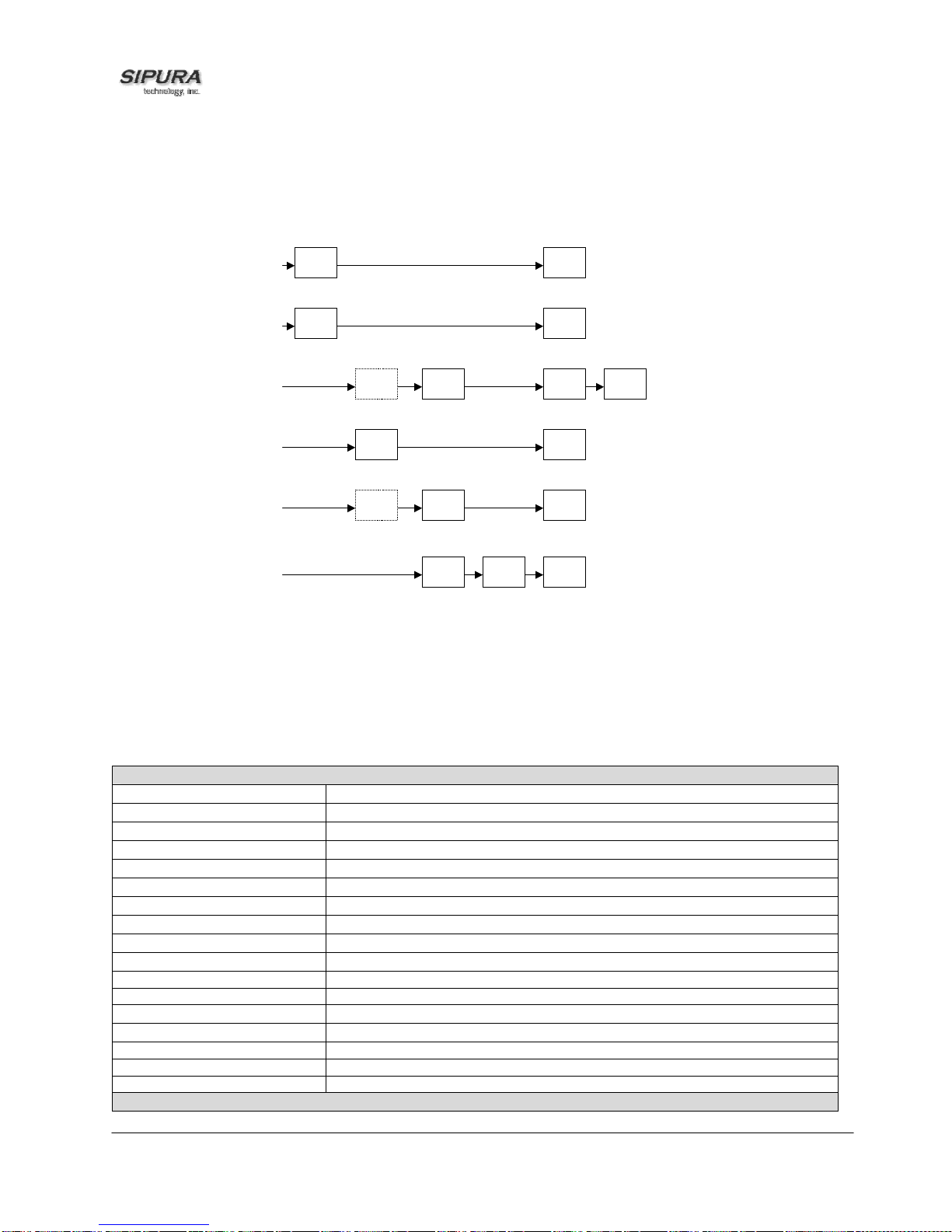
• Off Hook Caller ID – This is used to delivery caller-id on incoming calls when the attached phone is
off hook. See figure below (f). This can be call waiting caller ID (CIDCW) or to notify the user that the
far end party identity has changed or updated (such as due to a call transfer). This is only available if
the caller-id method is one of “Bellcore”, “ETSI FSK”, or “ETSI FSK With PR”.
a) Bellcore/ETSI Onhook Post-Ring FSK
First
Ring
b) ETSI Onhook Post-Ring DTMF
First
Ring
c) ETSI Onhook Pre-Ring FSK/DTMF
Polarity
Reversal
d) Bellcore Onhook FSK w/o Ring
OSI FSK
e) ETSI Onhook FSK w/o Ring
Polarity
Reversal
(DTAS)
(DTAS)
CAS
CAS
FSK
DTMF
DTMF/
FSK
FSK
First
Ring
f) Bellcore/ETSI Offhook FSK
CAS
(DTAS)
Wait For
ACK
FSK
Figure: SPA Caller ID Delivery Architecture
3.5. Call Statistics Reporting
The following lists the statistics collected by the SP A during normal operation. Thes e statistics are
presented in the SPA web- page (under the “Inf o” tab). Line stat us is reported f or each line (1 and 2) .
Each line maintains up to 2 calls: Call 1 and 2.
System Status
Current Time Current time and date. E.g., 10/3/2003 16:43:00
Elapsed Time Total time elapsed since last reboot. E.g., 25 days and 18:12:36
Broadcast Pkts Sent Total number of broadcast packets sent
Broadcast Pkts Recv Total number of broadcast packets received
Broadcast Bytes Sent Total number of broadcast bytes sent
Broadcast Bytes Recv Total number of broadcast bytes received and processed
Broadcast Packets Dropped Total number of broadcast packets received but not processed
Broadcast Bytes Dropped Total number of broadcast bytes received but not processed
RTP Packets Sent Total number of RTP packets sent (including redundant packets)
RTP Packets Received Total number of RTP packets received (including redundant packets)
RTP Bytes Sent Total number of RTP bytes sent
RTP Bytes Received Total number of RTP bytes received
SIP Messages Sent Total number of SIP messages sent (including retransmissions)
SIP Messages Received Total number of SIP messages received (including retransmissions)
SIP Bytes Sent Total number of bytes of SIP messages sent (including retransmissions)
SIP Bytes Received Total number of bytes of SIP messages received (including retransmissions)
External IP External IP address used for NAT mapping
Line 1/2 Status
© 2003 - 2004 Sipura Technology, Inc Proprietary (See Copyright Notice on Page 2)
36
Page 37

Hook State State of the hook switch: On or Off
Registration State Registration state of the line: Not Registered, Registered or Failed
Last Registration At Local time of the last successful registration
Next Registration In Number of seconds before the next registration renewal
Message Waiting Indicate whether new voice mails available: Yes or No
Call Back Active Indicate whether a call back request is in progress: Yes or No
Last Called Number The last number called
Last Caller Number The number of the last caller
Mapped SIP Port NAT Mapped SIP Port
Call 1/2 Status
State State of the call: Idle, Dialing, Calling, Proceeding, Ringing, Answering,
Connected, Hold, Holding, Resuming, or Reorder
Tone Tone playing for this call: Dial, 2nd Dial, Outside Dial, Ring Back, Ring,
Busy, Reorder, SIT1– 4, Call Waiting, Call Forward, Conference,
Prompt, Confirmation, or Message-Waiting
Encoder Encoder in use: G711u, G711a, G726-16/24/32/40, G729a, or G729ab
Decoder Decoder in use: G711u, G711a, G726-16/24/32/40, G729a, or G729ab
FAX Indicate whether FAX pass-through mode has been initiated: Yes or No
Type Indicate the call type: Inbound or Outbound
Remote Hold Indicate whether the remote end has placed the call on hold: Yes or No
Call Back Indicate whether the call is triggered by a call back request: Yes or No
Peer Name Name of the peer
Peer Phone Phone number of the peer
Duration Duration of the call in hr/min/sec format
Packets Sent Number of RTP packets sent
Packets Recv Number of RTP packets received
Bytes Sent Number of RTP bytes sent
Bytes Recv Number of RTP bytes received
Decode Latency Decoder latency in milliseconds
Jitter Receiver jitter in milliseconds
Round Trip Delay Network round trip delay (ms); available if the peer supports RTCP
Packets Lost Total number of packets lost
Packet Error Number of RTP packets received that are invalid
Mapped RTP Port NAT mapped RTP port
© 2003 - 2004 Sipura Technology, Inc Proprietary (See Copyright Notice on Page 2)
37
Page 38

4. SPA-3000 Configuration
4.1. Overview
The SPA-3000 has 1 FX S and 1 FXO port. Each p ort is a RJ11 connector – th e FXS Port is labeled
“PHONE” and the FXO Port “LINE.”
A standard analog telep hone c an be co nnect ed to the FXS/PHO NE por t to prov ide VoI P serv ices just
as with the SPA-1000 and SP A- 20 00. T he F X O/LINE por t c an be co nnec te d to a s tandar d PST N li ne
or other phone servic e – including a nother VoIP s ervice. W ith the FXO/LIN E port, the SPA-30 00 can
bridge a PSTN and a VoI P service. This functionality is r eferred to as a Gateway. We refer to the
VoIP-To-PSTN c alling function as a PSTN Gateway, and PSTN-To-VoIP ca lling function as a VoIP
Gateway. We also define:
- VoIP Caller – one who calls the SPA-3000 via VoI P to obtain PST N ser vic e.
- VoIP User – a VoIP Caller which has a user account (user-id and password) on the SPA-3000
- PSTN Caller – one who calls the SPA-3000 from the PSTN to obtain VoIP service.
Two VoIP services can be configured in the SPA-3000: one accessed from the FXS port and the
other from the FXO por t. In this document, the VoIP service that is accessed from the FXS/PHON E
port is referred to as the Line 1, and the VoIP service that is accessed from the FXO/LINE port is
referred to as the PSTN Line.
Notes:
- The term PSTN line (case sens itive), on the other hand, s tands for the PSTN service c onnected
to the FXO/LINE port.
- The notations [Line 1], [PSTN Line], etc., refer to the web page tabs appear on the SPA
configuration web page. Eac h tab repres ents a logic a l group of conf igur ati on para meters.
The configuration of Line 1 is similar to Line 1 in the SPA- 2000, with several additional opt ions for
PSTN-VoIP gatewa y configurations. Line 1 c an be configured with a regu lar VoIP account and used
in the same way as th e L in e 1 of the SP A- 20 00. A s ec ond VoIP account can be configured to supp or t
PSTN gateway calls exclusively. The options for controlling Line 1 and PSTN Line are configured
under the [Line 1] and [PS TN Line] tabs on the SP A-3000 c onfigur ation web page res pective ly. Li ne
1 works almost independently of the PSTN Line. In f ac t , Lin e 1 c an b e dis a ble d wit hout affecting most
of the operations on the PSTN Line. A different <SIP Port> parameter, however, should be assigned
to Line 1 and PSTN Line. T he s ame VoIP account may be used for both Li ne 1 an d the P ST N Line as
long as each line uses a different <SIP Port>.
The FXS/PHONE p ort can be electrically con nected to either the FX O/LINE port or the SLIC inside
the SPA-3000, by opening or closing an internal PHONE Port Relay (under the control of SPA
firmware). Befor e power is applied t o the unit, the rela y is open and the p hone is connected t o the
PSTN line.
After power is applied to the unit, the ACT LED will turn on and blink to indicate network activity
(transmit or receive) . The STATUS LED will also b link slowly to indicate DHCP dis covery (if DHCP
option is enabled in t he SPA) and hardware initia lization. If all goes well, the STATUS LED will tur n
off after 10-20s to indicate successful completion of hardware initialization. The ACT LED should
remain mostly steady on with oc casional blinks. Whenever you pick up the handset of the PHONE
port phone, the STATUS LED should become steady on until the phone is off-hook again.
Following successful hardware initialization, the relay must be closed at some point for normal
operation. However , there is a chance that the PHONE p ort phone ma y be using the PSTN line (v ia
the FXO/LINE port) an d closing the relay will therefore interrupt the call that is in progress (which
© 2003 - 2004 Sipura Technology, Inc Proprietary (See Copyright Notice on Page 2)
38
Page 39

would be highly undesir able espec iall y if the call is a n em ergenc y). The SPA-300 0 uses the f ollowing
algorithm to determine when to close the relay:
Off-Hook FXO port
Close PHONE Port Relay
If (Loop Current is 0) {
Done (since PSTN line is not connected or inactive)
}
Else {
If (PHONE Port is on-hook) {
Done (since it is not using the PSTN line)
}
Else {
Open Phone Port Relay (since PHONE port phone is using the PSTN line)
While (1) {
Monitor FXO port Tip-To-Ring Voltage
If (PSTN line is not in use) {
Close Phone Port Relay
Done
}
}
}
}
Notes:
- A mechanical click sound can be heard whenever the relay is open or closed.
- The STATUS light will be steady on if the FXO port or the FXS port is off-hook.
- Once the PHONE Port Relay is closed, it will not be o pen aga in unt il the po wer is rem oved.
- To be able to invoke the IVR (voice configuration menu), the PHONE Port Relay must be closed.
4.2. SPA-3000 Voice Configuration Organization
The SPA-3000 can be thought of as having 4 logical voice interfaces, namely,
- FXS Interface
- FXO Interface
- VoIP1 Interface
- VoIP2 Interface
Figure 4.1 shows a block diagram of the voice interfaces and the group of configuration parameters
for controlling t heir operations. It als o s ho ws the pos s i ble voic e pa ths with eac h segment labeled by a
number in parenthesis. We shall refer to the voic e pat h of a call as a co nnec te d li s t of the pat h labels,
such as (1) Æ (2) Æ (3) and (5) Æ (6) Æ (7). Please take a mom ent to familiarize your self with this
diagram. We will make reference to it very often as we describe the different configuration scenarios.
Like the SPA-2000, the SPA-3 000 configuration parameter s are organized into 8 groups, with each
group accessed by clic king the correspon ding tab on the top of the SPA web page. T hese 8 groups
are:
1. System – Network parameters, DNS, NTP, Syslog, and Debug Servers
2. Provisioning – Profile rule, resync intervals and policy, and GPP
3. SIP – SIP stack control parameters for both VoIP interfaces
© 2003 - 2004 Sipura Technology, Inc Proprietary (See Copyright Notice on Page 2)
39
Page 40

4. Regional – Call progress tones and cadences, ring cadences, * codes, international control
for the FXS Interface. The tone and cadence parameters also apply to the VoIP2 and FXO
interfaces
5. Lin e 1 – Audio, NAT , SIP, Network, Gateway, Supplementary Services, Polarit y parameters
for VoIP1 and FXS
6. PSTN Line – Audio, NAT, SIP, and Network parameters for VoIP2
7. User 1 – User options for VoIP1 and FXS
8. PSTN User – User options for VoIP2 and FXO
In addition, there is a 9
th
group under the Info tab whic h s ho ws a number of read-only parameter s and
status information.
Phone
(1)
[Line 1]
[User 1]
[Regional]
FXS VoIP1
(2)
[SIP]
(3)
PSTN
(7)
PSTN line
(8)
FXO VoIP2
[PSTN Line]
[PSTN User]
[Regional] (partial)
(6)
(4)
(5)
[SIP]
Figure 4.1: SPA-3000 Voice Paths and Configuration Architecture
4.2.1. FXS Interface
This is the interface to the FXS/PHONE Port through which the user accesses the Line 1 VoIP
service. It controls ho w the SPA exchanges signals with the phone attached to FXS/PHONE port. It
supplies power to the ph on e an d s e ns es its on/off hook state. This interface can be c onf ig ur ed un der
the [Regiona], [Line 1], and [User 1] tabs.
Options that can be configured on the FXS Interface include:
• Polarity reversal signal generation
• CPC signal generation
• Ringer characteristics
• Call progress tones generation
• Transmit and receive gains
• DTMF playback level and timing
• Caller-ID delivery signal format
• Voice-Mail messages waiting indication
• Impedance
• On/off hook and hook flash detection timing
• FAX tones detection
© 2003 - 2004 Sipura Technology, Inc Proprietary (See Copyright Notice on Page 2)
40
Page 41

The FXS interface is the same as that in the SPA-2000. Please refer to the SPA-2000 sect ion for
more details on configuration of this interface.
4.2.2. FXO Interface
This is the interf ace to the F XO/LINE port. It c ontrols the exchange of s ignals betw een the SPA and
the PSTN line attached to the F XO/LINE port. It draws power from the PSTN lin e and controls the
on/off hook state. T his interface can be configure d under the [Regional] and [PS TN Line] tabs, with
the following functions:
- Polarity revers al detection: SP A can detect polar ity reversal of the tip-to-ring volt age as a PSTN
disconnect signal (section 4.7)
- CPC signal detection: SPA can detect CPC or momentary removal of tip-to-ring voltage as a
PSTN disconnect signal (section 4.7)
- Disc onnect Tone detectio n: SPA can detect th e occurr ence of disc onnect t one on the PSTN line ;
the characteristics of this tone is configurable (section 4.7)
- PSTN v oice activit y detection: SPA can m onitor voic e activit y on the PST N line and co nsider the
call has ended if no activity for a long period (section 4.7)
- Ring detection: The characteristic s of the ringing signal to detect c an be finely adjus ted with the
following parameters :
o <Ring Frequency Min> - lower limit of the frequency of valid ring signal
o <Ring Frequency Max> - upper limit of the frequency of valid ring signal
o <Ring Validation Time> - minimum duration of valid ring signal
o <Ring Threshold> - minimum Vrms of a valid ring signal
o <Ring Timeout> - delay in de-asserting a ring signal after it is removed from the PSTN line
o <Ring Indication Delay> - delay in assert ing a ring signal after it is detected on the PSTN line
- DTMF detection: Detects DTMF digits on the PSTN line
- FAX Tones detection: Detects FAX CED and CNG tones on the PSTN line
- Parallel handset detection: SPA detects if the PSTN line is being used by another extension
sharing the line, if the tip-to-r ing volt ag e drops belo w the <Line- In- Us e Vo lta ge >
- <SPA to PSTN Gain>: Increase or decrease the signal level sent to the PSTN line. The valid
range is from -15 dB to 12 dB in 1 dB increment. Note: Increasing this gain may increase the level
of echo heard on the VoIP call leg, while decreasing it may reduce the level of the same echo
- <PST N to SPA Gain>: Increase or decrease the signal l evel received from the PST N line. The
valid range is f rom -15 dB to 1 2 dB in 1 dB incr ement. Note: Increas ing this gain m ay increase
the level of the echo heard on the VoIP call leg, while decr easing it may reduce the level of the
same echo
- Caller-ID detec tion and decoding: SPA can detect and decode Bellcor e Type I Caller-ID (FSK)
signal on the PSTN line after the first ring
- <FXO Port Impedance>: SPA supports 16 impedance settings
- Sends these signals to the PSTN Line: Tones, DTMF, On/Off Hook
- Miscellaneous parameters for international compliance control:
o <Tip/Ring Voltage Adjust> - Adjust the Tip/Ring voltage on the PSTN line
o <Operational Loop Current Min> - Adjust the minimum loop current at which the SPA can
operate
o <Curren t Limiting Enable > - If enabled, it l imits the loop current to a maximum of 60mA per
the TBR21 standard
o <Ringer Impedance> - Set the impedance of the ringer
o <On-Hook Speed> - Adjust the time for the loop c urrent to drop to 0 after the S PA takes the
FXO port on-hook
To get the most out of your SPA-3000, it is highl y recommended to connect a PST N service to the
LINE port with Type I Caller-ID subscription. This will allow the following additional functionalities:
© 2003 - 2004 Sipura Technology, Inc Proprietary (See Copyright Notice on Page 2)
41
Page 42

- Limit the use of the gateway by PSTN Caller-ID number
- Selectively forward PSTN callers to different VoIP destinations
Notes:
- The <Cal ler-ID Method > param eter under [Regio nal] tab onl y controls the Ca ller-ID sign al format
sent by the SPA t o t he Ca ll er- ID de vic e a ttac he d t o t h e FX S/ PHO NE p or t; it does not apply to the
caller-id signal f orm at sent to the SP A by the PSTN switc h via th e FXO/LIN E port. At pr esent th e
SPA can only decode Bellcore FSK style Caller-ID signal sent by the PSTN switch.
4.2.3. VoIP Interfaces
There are 2 VoIP i nterfaces in t he SPA-3 000. Each V oIP interf ace can be co nfigured t o register with
a VoIP Service Provid er ( VSP), and to r eceive a nd m ake calls over the IP n et work . Dependin g on the
functionality you have in mind, you can configure either or both interfaces. The VoIP1 and VoIP2
interfaces correspond to the Line 1 VoIP service, and the PSTN Line VoIP service, respectively.
The [SIP] parameter group and a portion of the [Regional] parameter group apply to both VoIP
interfaces. The [Line 1] an d the [User 1] parameter groups are dedicated to VoI P1, while the [PSTN
Line] and the [PSTN User] parameter groups to VoIP2.
VoIP1 and VoIP2 interfaces can be configured independently with the same or different VSP. The
same VSP account can be configured for both interfaces but the <SIP Port> parameter must be
different for each interface in this case.
Most VSP require the following parameters configured on a VoIP interface:
- <Proxy>
- <User ID>
- <Password>
- <Register>
- <Register Expires>
Some VSP may also require the following parameters to be configured:
- <Outbound Proxy> (from VSP) and <Use Outbound Proxy> = yes
- <Auth ID> and <Use Auth ID> = yes
4.2.4. Call Types
The type of calls supported by the SPA-3000 can be described in terms of the originating,
intermediate, and terminating interfaces involved:
1. FXS to VoIP1
2. VoIP1 to FXS
3. FXO to VoIP2
4. VoIP2 to FXO
5. VoIP1 to FXO
6. FXO to VoIP2 to VoIP1 to FXS
7. FXS to VoIP1 to VoIP2 to FXO
#1 and #2 are conv entional VoIP calls . #3 lets a PSTN c aller hop-on to use Vo IP service. #4 le ts a
VoIP caller hop-off to use PST N ser vice. #5 is sim ilar to #4 except the c aller es tablis hes the VoIP cal l
leg by calling the VoIP1 int erface instead of the Vo IP2 interface. #6 allo ws the PSTN call to ring the
FXS port phone; we called this “ringing thru”. #7 allows you to call the PSTN from the phone.
Notes:
© 2003 - 2004 Sipura Technology, Inc Proprietary (See Copyright Notice on Page 2)
42
Page 43

- VoIP1- to-VoIP2 a nd VoI P2-to-VoI P1 are inte rnal SIP calls. Sig naling an d media pac kets ar e sent
to the loop back addres s 127.0. 0.1. Hence call t ypes #6 and #7 ar e possi ble eve n if the Eth ernet
port is not connected
The following sections describe each type of calls in more details.
4.2.5. Determining the Availability of the PSTN line
SPA determines that the PSTN line is not available if the one of the following conditions is true:
- PSTN line is not connected (loop current is 0 or Tip/Ring RMS voltage is below 1V)
- PSTN line is being used by another extension. T ip/R in g RMS vo lta ge l o wer th an t he thr es h old set
in <Line-In-Use Volt age>
- PSTN line is ringing
- PSTN line is being used by the SPA to serve another VoIP caller
If the PSTN line is not available, the PSTN gateway function will be rejected; any VoIP caller
requesting PSTN gateway functions will be turned down with a “Service Not Available” response.
4.3. Gate way Call Restricti on by Dial Plan
Gateway calls can be restricted on a per caller basis using dial plans. Up to 8 dial plans can be
configured to restrict gateway calls in either direction. The corresponding SPA parameters are:
- [PSTN Line]<Dial Plan n>, n = 1 to 8
Notes:
- T he dial plan length lim it for <Dial Plan 1> through <Dial Plan 8> is 511 char acters. This is
less than that for the <Dial Plan> under [Line 1], which is 2047 characters.
- “gw0” – “gw4” syntaxes are not applicable to <Dial Plan 1> – <Dial Plan 8> (section 4.8)
- While PSTN-T o-VoIP calls must have d ial plan (1 – 8) spec ified, the dial plan c an be set to
“none” for VoIP-To-PST N calls. If the dial plan is “ none”, the SPA will take the FX O port offhook and the VoIP caller will hear the PSTN dial tone directly from the PSTN switch
immediately after s uccessful authentication; the target number dialed by the VoIP caller will
be directly interpreted by the PSTN company. On the other hand, if the dial plan is not “none”,
the VoIP caller will hear the “Outs ide Dial Tone” g enerated by the SPA, where th e caller will
dial the target PSTN num ber. This number will be received and process ed by the SPA with
the chosen dial plan (the FXO port is still on-hook while the caller is entering the target
number). If the target number is valid, the SPA then takes the FXO port off-hook and
automatically dials the final target number (according to the chosen dial plan) out to the
PSTN line. The characteristics of the Outside Dia l Tone can be changed b y modifying the
<Outside Dial Tone> parameter (under [Regional] tab).
- You can “forward” all VoIP callers of the PSTN Line to a certain PSTN number (with or
without authenticatio n) by setting a hot line rule in the d ial plan, suc h as (S0<:1408 9991234>)
which sends all callers to 14089991234 automatically once the SPA auto-answers and
authenticates the VoIP call. To make this works more transparently to the caller, you may
disable authentication or add the caller to the access list.
© 2003 - 2004 Sipura Technology, Inc Proprietary (See Copyright Notice on Page 2)
43
Page 44

4.4. Authentication Methods
VoIP Callers can be authentic ated by one of the following m ethods by setting th e <VoIP Caller Auth
Method> parameter:
1. No Authe ntication: All callers will be accepted for service. T he dial plan to be used for all VoIP
callers for this case is the one selected in <VoIP Caller Default DP>.
2. PIN: Cal ler is prompted to enter a V oIP PIN right after the call is answered (i.e., after the SPA
replies with a 200 respons e). Up to 8 PIN’s, < VoIP C aller 1 PI N> to < VoIP Calle r 8 PIN>, c an be
setup to access the PST N gateway a nd each PIN can be assig ned a dif ferent dia l plan us ing th e
<VoIP Caller 1 DP > to < VoIP Cal ler 8 DP> param eters, re spective ly. The c aller will h ear a b eepbeep-beep tone, kno wn as the VoI P PIN Tone, as the prompt to enter the VoIP PI N. T he ton e wil l
be played repeatedl y until a PIN digit is r eceived. Af ter the f irst digit, the us er b y default will h ave
10s to enter each s u bsequ ent PIN digit. If no n e w PIN di git is ent er ed f or more than 10s, the SP A
will terminate the call. This inter-PIN-digit timeout is set in the <VoIP PIN Digit Timeout>
parameter. The PIN number entry must be ended by a pound (#) key. By default the caller will b e
given 3 chances to enter a valid PIN. If no valid PIN is received after 3 trials, the SPA will
terminate the call. The nu mber of VoIP PIN entry trials to allow can be chan ged by setting the
<VoIP PIN Max Retry> param eter. If the last PIN entr y is invalid, the VoIP P IN Tone will resum e
and the caller can re-enter the PIN again. The characteristics of the VoIP PIN Tone can be
changed by setting <VoIP PIN Tone> ([Regional] tab). T he VoIP PIN Tone should be set with a
finite timeout (the def ault VoIP PIN tone has a timeout value of 10s ). If no valid PIN is received
after the maximum number of trials, the SPA will terminate the call.
3. HTTP Digest: SIP INVIT E must contain a va lid Authorization h eader that is computed bas ed on
an Auth ID and a pas sword using MD5 digest algorit hm. The Auth ID must be specif ied in the
username param eter in the Author ization h eader. Up t o 8 Aut h ID/Pass words, <V oIP User 1 Au th
ID>/<VoIP User 1 Passwor d> to <VoIP Us er 8 Aut h ID>/<VoIP User 8 Pas sword>, can be setup
to access the PSTN gatewa y. Each Auth ID/ Pass word c an be assign ed a dif ferent dia l plan us ing
the <VoIP User 1 DP> to <VoIP User 8 DP> param eters, respectively. If the inb ound INVITE to
the PSTN Line does not h ave an Authorization hea der or the credentials it cont ains are invalid,
the SPA will repl y with a 401 response. If the user name parameter in the Autho rization header
does not match any of the <VoIP User n Auth ID>, n = 1 to 8, the SPA will reply with a 403
response. If the INVITE request a target PSTN number (as in one-stage dialing) that is not
allowed by the corresponding dial plan for that caller, the SPA will also reply with a 403 response.
VoIP callers can also be gated b y a list of Caller-ID patterns bef ore authenticatio n rules are applied.
These patterns are s pecifie d in <VoIP Ca ller ID Pa ttern> which is a com ma sepa rate list of Caller-ID
patterns. The VoIP Caller-ID is extracted from the inbound INVITE request FROM header User-ID
field. If the FROM header has “Anon ymous” (cas e-inse nsiti ve) in the d ispla y-nam e f ield, however , the
SPA treats the VoIP Ca ller-ID as “Anonymous”. Each Caller- ID pattern is a case insensitive alphanumeric string with spec i al wil dca rd c har acter s ‘? ’ an d ‘*’ , whic h s ta nds f or “ an y singl e di git” a nd “0 or
more of any digits” respectively. For example: 1408*,15101234567,18??*,anonymous,jsmith. It is
recommended not to ins ert white spaces before and after the comma, although the y are allowed. If
<VoIP Caller ID Pattern> is blank, all VoIP callers will be processed by the SPA for authentication and
subsequent gateway services upon successful authentication. If <VoIP Caller ID Pattern> is not
blank, then the VoIP Calle r ID must match one of the given patterns or else will be r ejected by the
SPA with a 403 response without further processing.
In addition, a VoIP Caller can be automatically accepted for PSTN gateway access without going
through the authenticatio n process if the sour ce IP address of the inboun d INVITE request matc hes
one of the pattern specif ied in the <Vo IP Access Lis t>. This is a com ma separated lis t of IP address
patterns, also with special wildcard characters ‘?’ and ‘*’. For example:192.1 68.2.*,66.12?.12?.4. If
the list is not blank and the s ource IP address of the inbou nd INVITE matches any of the patterns in
the list, the VoIP cal ler wil l be gra nted ac c es s to the P STN gateway as if the Auth entic a tion Method is
© 2003 - 2004 Sipura Technology, Inc Proprietary (See Copyright Notice on Page 2)
44
Page 45

set to “none” (and so the <VoIP Caller Default DP> applies and 1-stage dialing is possible in this
case).
Notes:
- One-stage dialing is possible only if <VoIP Caller Auth Method> is “none” or “HTTP Digest”.
Unless the caller number is in the < VoI P Ac c ess Lis t >, the “ PIN” m ethod r equ ires 2- s tage dial ing :
Caller will need to di al the tar get PSTN num ber after enter ing a valid PIN. One-st age dialing c an
be globally disabled by setting <One Stage Dialing> to “no”, for which case all VoIP callers
(including Line 1) will be required to dial the PSTN target number upon successful authentication.
- If the V oIP Caller is cal ling f rom Line 1 of the sam e unit. Authentic ation is s kipped regardles s the
setting of <VoIP Ca ller Auth Method>. The dial p lan to use in this case in <Line 1 VoIP Caller
DP> for normal operatio n, or <Line 1 Fal lback DP> fo r Line-1-F all back -To -PST N operatio n (when
network link is down or Line 1 registration fails).
PSTN Callers can be authenticated by one of the following methods by setting the <PSTN Caller Auth
Method> parameter:
1. No Auth ent ic at ion: A ll C al ler s wil l be ac c epte d f or ser v ic e. In th is c ase the dial plan to be us e d f or
all PSTN callers is taken from <PSTN Caller Default DP>.
2. PIN: Caller is prompted t o enter a PST N PIN right after the call is auto-ans wered b y the SPA ( by
taking the FXO port off-hook ). Up to 8 PIN’s, <PST N Caller 1 PIN> to <PST N Caller 8 PIN>, can
be setup to access the VoIP gateway and eac h PIN can be assigned a different dial plan us ing
the <PSTN Caller 1 D P> to <PST N Caller 8 D P> para meters, r espectively. T he caller wil l hear a
beep-beep-beep tone, k nown as th e PSTN PIN Tone, as the prom pt to enter the PSTN PIN. The
tone will be played repe atedly until a PIN digit is rec eived. After the first dig it, the user b y default
will have 10s to enter each s ubs eque nt PI N dig it. If no ne w PIN dig it is entered for more than 10s,
the SPA will play the Reorder T one and then terminate the cal l by taking the FXO port on-hook .
This inter-PIN-digit tim eout is set in the <PSTN PIN Digit T imeout> parameter. The PIN num ber
entry must be ended b y a pound (#) ke y. By default the caller will b e given 3 chances to enter a
valid PIN. If no valid PIN is received after 3 trials, the SPA will ter minate the call. The number of
PSTN PIN entry tria ls to all ow can be chang ed b y sett ing th e <PST N PIN Max R etr y> param eter.
If the last PIN entry is inva lid, the P STN PIN T one will r esum e and the caller can re- enter the PI N
again. The characteristics of the PSTN PIN Tone can be changed by modifying <PSTN PIN
Tone> ([Regional] t ab). The PSTN PIN Tone sh ou ld b e s et with a f in ite t imeout (the default P ST N
PIN tone has a timeout value of 10s). If no valid PIN is received after the maximum number of
trials, the SPA will play reorder tone and then terminate the call.
PSTN callers can also b e gated b y a list of Ca ller-ID p atterns bef ore authe nticatio n rules are applied.
These patterns are specified in <PSTN Caller ID Pattern>, a comma separate list of Caller-ID
patterns. The PSTN Caller -ID is decoded from the signal deli vered by the PSTN switch. It is highl y
recommended that t he PSTN line connecte d to the SPA comes with t he caller-id deli very service. If
Caller-ID signal is not pres ent or the Caller-ID number is block ed, the SPA treats the PSTN Ca ller-ID
as “Anonymous”. Each Caller-ID number is a case-insensitive alphanumeric string with special
wildcard characters ‘?’ and ‘*’ , which stands for “any single digit” and “0 or more of any digits”
respectively. For example: 1408*,15101234567,18??*,anon ymous. It is recommended not to insert
white spaces befor e and after the comm a, although the y are allowe d. If <PST N Caller ID Patter n> is
blank, all PSTN callers will be processed by the SPA for authentication and subsequent gateway
services upon successful authentication. If <PSTN Caller ID Pattern> is not blank, then the PST N
Caller ID must match one of the given patterns or else the SPA will not answer the call.
In addition, a PSTN caller can be automatically accepted for VoIP gateway access without going
through the authent ication process if the Cal ler-ID number matches one of the patterns specif ied in
the <PSTN Access List>. This is a comma separated list of Caller-ID patterns, also with special
© 2003 - 2004 Sipura Technology, Inc Proprietary (See Copyright Notice on Page 2)
45
Page 46

wildcard characters ‘? ’ and ‘*’ (s ame s yntax as <PSTN Caller ID Pattern>). If the list is not b lank and
the Caller-ID number matches any of the patterns i n the list, that PSTN c aller will be granted acc ess
to the VoIP gateway as if the Authentication Method is set to “none” (and so the <PSTN Caller Default
DP> applies in this case).
Notes:
- Only 2-stage dialing is possible with PSTN-To-VoIP gateway calls
The configuration parameters mentioned in this section are:
- [PSTN Line]<One Stage Dialing>
- [PSTN Line]<VoIP Auth Method>
- [PSTN Line]<VoIP Caller ID Pattern>
- [PSTN Line]<VoIP Access List>
- [PSTN Line]<VoIP PIN Max Retry>
- [PSTN Line]<VoIP PIN Digit Timeout>
- [Regional]<VoIP PIN Tone>
- [PSTN Line]<VoIP Caller Default DP>
- [PSTN Line]<VoIP Caller n PIN>, n = 1 to 8
- [PSTN Line]<VoIP Caller n DP>, n = 1 to 8
- [PSTN Line]<VoIP User n Auth ID>, n = 1 to 8
- [PSTN Line]<VoIP User n Password>, n = 1 to 8
- [PSTN Line]<VoIP User n DP>, n = 1 to 8
- [PSTN Line]<Line 1 VoIP Caller DP>
- [PSTN Line]<Line 1 Fallback DP>
- [PSTN Line]<PSTN Auth Method>
- [PSTN Line]<PSTN Caller ID Pattern>
- [PSTN Line]<PSTN A ccess List>
- [PSTN Line]<PSTN PIN Max Retry>
- [PSTN Line]<PSTN PIN Digit Timeout>
- [Regional]<PSTN PIN Tone>
- [PSTN Line]<PSTN Caller Default DP>
- [PSTN Line]<PSTN Caller n DP>, n = 1 to 8
4.5. VoIP-To-PSTN Calls (Call Type #4)
In order to obtain P STN services via V oIP, the VoIP call er must establish con nection with the SP A3000 by way of a standard SIP INVIT E request addressed to the SIP account c onfigured under the
[PSTN Line] tab. The PST N gateway can be configured to support 1-stage and 2-stage dialing as
described below. This is call type #4 and the voice path for this type of calls is (5)Æ(6)Æ(7)
4.5.1. One-Stage Dialing
One-stage dialing is pos s ibl e if <One Stage Dialing> is “yes”, <VoIP Authentic at ion Metho d > is “ no ne”
or “HTTP Digest” or if the source IP of the inb ound INVITE m atches one of the patterns s pecified in
<VoIP Access List>. T o perf orm one- stage dialing, t he Reques t-URI of the IN VITE to the P STN Line
should have the form dialed-number@SPA-Address, where dialed-number is the target PSTN
number as “dialed” by the VoIP caller, and SPA-Address is a valid address of the SPA, such as
10.0.0.100:5061.
If the PSTN line is currently not available, the SPA replies to the INVITE with a 503 response.
Otherwise, it compar es the dialed-number with the <User ID> configur ed for the PSTN Line. If the
© 2003 - 2004 Sipura Technology, Inc Proprietary (See Copyright Notice on Page 2)
46
Page 47

dialed-number is not spec if i ed or is the s am e as <Us er ID>, the S PA i nterprets this as a request for 2stage dialing (see next section). Otherwise, the SPA processes the dialed-number by a
corresponding dial plan. If the dial plan processing fails, the SPA replies with a 403 response.
Otherwise, it replies with a 200 respo nse and at the sa m e time takes the FX O port off hook and dials
the final number returned from the dial plan to the PSTN switch.
4.5.2. Two-Stage Dialing
In 2-stage dialing, the VoIP caller will need to dial the target PSTN number upon successful
authentication. If the d ial plan c onfigur ed f or this VoI P c aller is “none” , SP A will t ak e the FX O port off hook but will not dia l a n y digits a utomatically after acc epti ng t he caller for gateway s erv ic e. H enc e t he
caller will hear the dial tone directly provided by the PSTN switch, which will interpret the target
number dialed b y the VoIP caller. If the dial plan is not “none”, the S PA will play the Outside Dial
Tone to direct the VoI P call er to dial the PST N num ber; the F XO por t wil l sta y on-hook while th e SPA
collects a complete PSTN target number from the caller according to the selected dial plan. If the
dialed number is valid, the SPA takes the FXO port off-hook and dials the final target number
returned from the d ial plan to the P STN switch accordin gly. If the dialed n umber is invalid, the SPA
terminates the call immediately.
To invoke 2-stage dialing, the VoIP ca ller can form a SIP INVITE request to send the PST N Line
without a user-id fie ld in the Re quest-URI or with a user- id that m atches exac tly the <Us er ID> of the
PSTN Line. Other user- id in the Request- URI will be treated as a requ est for 1-stage dia ling (Sec tion
4.5.1) if 1-stage dial ing is e nabled, or dr opped b y the SPA (as if no user -id is g iven) if 1- stage dia ling
is disabled.
The VoIP PIN digits and target number digits must be sent to the SPA out-of-band using the
RFC2833 protocol (a.k .a. AVT Tone). The SP A does not accept an y DTMF digits sent to it in-b and
over VoIP.
Notes:
- VoIP-T o-PSTN Gateway function can be globally disa bled by setting <VoIP-To-PSTN Gatewa y
Enable> to “no”; SPA will reply with a 503 response to inbound INVITE sent to the PSTN Line
- If the PST N line is not connected, or is in use by an other extension or an other VoIP caller, the
SPA will reply with a 503 response to inbound INVITE sent to the PSTN Line
- The <User ID> of the P STN Line can be blank. In th at case Registration shou ld be disabled for
the PSTN Line
- W hen the SPA decides to accept an incoming INVIT E, it immediately sends a 180 response to
the VoIP caller, and eventually a 200 response to “answer” the call. You can set the desired delay
before the SPA sends o ut the 200 respons e after the 180 r esponse in the <VoIP Ans wer Delay>
parameter. This delay can be 0.
- You can i nsert a sm all amount of dela y before the S PA starts auto-dialing th e final target num ber
to the PSTN line after the SP A takes the F XO port off-hook . This dela y is specif ied in the <PST N
Dialing Delay> parameter. T his delay is used to make sure the PSTN switch is ready to rece ive
DTMF before the SPA starts dialing.
Below is the pseudo code for accepting a VoIP caller for PSTN gateway service.
If (VoIP Caller-ID Pattern Blank or VoIP Caller-ID Matches a VoIP Caller-ID Pattern) {
If (VoIP Caller in VoIP Access-List or Authentication Disabled) {
Reply 200
Start PSTN Gateway Service
}
Else {
© 2003 - 2004 Sipura Technology, Inc Proprietary (See Copyright Notice on Page 2)
47
Page 48

If (Authentication Method is HTTP) {
If (Authorization Invalid) {
Reply 401
}
Else {
If (Target Number Valid) {
Reply 200
Start PSTN Gateway Service
}
Else {
Reply 403
}
}
}
Else {
Reply 200
Get VoIP PIN from Caller
If (Valid PIN) {
Start PSTN Gateway Service
}
Else {
Send BYE
}
}
}
}
Else {
Reply 403
}
The configuration parameters mentioned in this section are:
- [PSTN Line]<One Stage Dialing>
- [PSTN Line]<VoIP Caller Auth Method>
- [PSTN Line]<VoIP Access List>
- [PSTN Line]<VoIP Caller ID Pattern>
- [PSTN Line]<VoIP Caller n PIN>, n = 1 to 8
- [PSTN Line]<VoIP User n Auth ID>, n = 1 to 8
- [PSTN Line]<VoIP User n Password>, n = 1 to 8
- [PSTN Line]<VoIP Caller n DP>, n = 1 to 8
- [PSTN Line]<VoIP User n DP>, n = 1 to 8
- [PSTN Line]<User ID>
- [PSTN Line]<VoIP-To-PSTN Gateway Enable>
- [PSTN Line]<VoIP Answer Delay>
- [PSTN Line]<PSTN Dialing Delay>
4.6. PSTN-To-VoIP Calls (Call Type #3)
This is call type #3 with th e voice path (7) Æ(6)Æ(5). PSTN-To- VoIP Calls can be m ade with 2-stage
dialing only. The only authentication method available is the PIN method. The SPA auto-answers
(i.e., takes the FXO por t off-hook) after the PSTN line rings for a c ertain number of seconds. This
auto-answer delay is configured in the <PSTN Answer Delay> parameter, and should be set to a
larger enough value to allow enough time for the SPA to decode the Caller-ID signal sent by the
© 2003 - 2004 Sipura Technology, Inc Proprietary (See Copyright Notice on Page 2)
48
Page 49

switch (for US telcos, this value shoul d be at least 3-4s ). If <PSTN Caller Auth Metho d> is “PIN”, the
SPA then prompts the caller to en ter the PIN num ber. If the g iven PIN m atches one of <PST N Caller
n PIN> values, the SPA p lays the D ial Tone to the FX O port and is r eady to acc ept digits of the VoIP
target number from the PS T N caller . T he c ollec te d di g its wil l be proc es sed by the dial plan associated
with the PIN number. If <PSTN Caller Auth Method> is “none”, the SPA plays the Dial Tone
immediately right af ter it auto-answers the PSTN call; the <PSTN Caller Default DP> is used for all
PSTN Callers for this case. Note that the chosen dial plan for any PSTN caller cannot be “none”.
If the caller enters a val id PSTN number accor ding to the chosen dial plan, the PST N generates an
INVITE to establish the VoIP call leg via the VoIP2 in terface configured under the [PSTN Line] tab.
The From header of the INVIT E will be the VoIP2 account, or substituted with the P STN Caller-ID
name and number if they are sent by the PST N switch and decoded successf ully by the SPA and
<PSTN CID For VoIP CID> is s et to “yes”. Furthermore, the S PA will prepend the PSTN Caller-ID
name and number with th e pref ix es c onf igured in <P S TN CID Name Perfix> and <P ST N CID Number
Prefix> respectively.
Notes:
- PSTN-To-VoIP Gateway service can be globally disabled by setting <PSTN-To-VoIP Gateway
Enable> to “no”. In that case, the SPA will not auto-answer any PSTN calls
- If the <Line En ab le> ([ PST N Line] tab) is “n o”, or VoIP 2 is not s ucc essf ully regis ter ed and <Mak e
Call Without Reg> ([ PSTN Line] tab) is “ no”, or the Ether net link is down, t he SPA will not autoanswer the PSTN call as if <PSTN-To-VoIP Gateway Enable> is set to “no”.
- Speed dial is allowed by the PSTN caller; 8 speed dials can be configured under [PSTN User] tab
- You can “ forward” PST N callers unc onditional ly with a hot line or warm line rule in the c hosen dial
plan, after the caller is successfully authenticated
- SPA supports selective call forwarding or blocking of PSTN callers such that a PSTN caller is
either “forwarded” to a fixed VoI P number or “bar red” from accessing the VoIP gateway (the call
will not be answered by the SPA in the latter case). Selective call forwarding and blocking
functions are conf igured under [ PSTN User]. S PA does not aut henticate the PSTN caller if he is
configured to be forwarded.
Below is the pseudo code for accepting a PSTN caller for VoIP gateway service.
If (PSTN Caller ID Pattern Blank or PSTN Caller-ID Matches a PSTN Caller-ID Pattern) {
Auto Answer (Off-Hook FXO Port)
If (PSTN Caller-ID in PSTN Access-List or Authentication Disabled) {
start_service:
Play Dial Tone
Collect VoIP Target Number Digits from Caller
If (Target Number Valid) {
Start VoIP Call
}
Else {
Play Reorder Tone
Hang Up
}
}
Else {
Get PSTN PIN from Caller
If (Valid PIN) {
Goto start_service
}
Else {
Play Reorder Tone
Hang Up
}
© 2003 - 2004 Sipura Technology, Inc Proprietary (See Copyright Notice on Page 2)
49
Page 50

}
}
The configuration parameters mentioned in this section are:
- [PSTN Line]<PSTN-To-VoIP Gateway Enable>
- [PSTN Line]<Line Enable>
- [PSTN Line]<Make Call Without Reg>
- [PSTN Line]<PSTN Caller ID Pattern>
- [PSTN Line]<PSTN A ccess List>
- [PSTN Line]<PSTN Answer Delay>
- [PSTN Line]<PSTN CID For VoIP CID>
- [PSTN Line]<PSTN CID Number Prefix>
- [PSTN Line]<PSTN CID Name Prefix>
- [PSTN Line]<PSTN Caller Auth Method>
- [PSTN Line]<PSTN Caller n PIN>, n = 1 to 8
- [PSTN User] <Speed Dial n>, n = 2 to 9
- [PSTN User]<Cfwd Seln Caller>, n = 1 to 8
- [PSTN User]<Cfwd Seln Dest>, n = 1 to 8
4.7. Terminating Gateway Calls
A gateway call has t wo ca ll legs : t he P STN call leg and the VoI P c all l eg. A g ateway call is term inated
when either call leg is e nded. It is ver y important th at the SPA tak es the FXO port on- hook when the
call terminates or else the PSTN l ine cannot b e used again. T he SPA det ects th at the PST N call le g
is ended when one of the following conditions occur during a call:
1. The PSTN line tip-to-ring voltage drops to a very low value (< 1V) for a finite duration of time. This
can happen if the PST N line is dis connecte d from the FXO port, or when the PST N switch s ends
a CPC signal to indicate that the call has been disconnected. The duration of this very low voltage
must last for at le ast t he le ngth as spec if ied in <Min C PC D uration >. T he det ectio n of CP C signa l
can be turned off by setting <Detect CPC> to “no”.
2. A polarit y reversal is d etected at the FXO port. The polarit y reversa l must last f or at least 100ms
or it will be ignored by the SPA. The detection of polarity reversal signal can be turned off by
setting <Detect Polarity Reversal> to “no”
3. Dis connect Tone detected on t he FXO port. The char acteristics of the Disc onnect Tone can be
changed by modif ying the <Dis connect Tone > param eter. The detec tion of D isconnect T one can
be turned off by setting <Detect Disconnect Tone> to “no”
4. When there is no voice activity det ected from the PSTN l ine for a cont inuous peri od of time. T he
condition must last in continuation for at least the length of time specified in the <PSTN Long
Silence Duration> par ameter. The sensitivit y of the detection can be adjusted b y setting <PSTN
Silence Threshold>; t he higher the threshold, the easier the SPA will detec t voice activity. The
detection of this condition can be turned off by setting <Detect PSTN Long Silence> to “no”.
The SPA determines that the VoIP connection is ended (or broken) if:
1. SPA receives a SIP BYE request from the VoIP peer
2. No RTP pack ets received from the VoIP Pe er for a continuous period of time larger than <VoIP
Long Silence Duration> seconds. The detection of this condition can be turned off by setting
<Detect VoIP Long Silence> to “no”
3. VoIP peer fails to respond to a periodic dialog refresh request from the SPA. The interval
between periodic ref resh mess ages is s et in the <VoIP DLG Ref resh Intvl>. T he ref res h mess age
© 2003 - 2004 Sipura Technology, Inc Proprietary (See Copyright Notice on Page 2)
50
Page 51

is a SIP Re-INVITE request which the VoIP peer must reply with a 200 class response. The
sending of dialog refresh messages can be disabled by setting <VoIP DLG Refresh Intvl> to 0.
When any of the above occurs, the SPA takes the FXO port on hook and sends the proper SIP
signaling messages to end the VoIP call leg. In addition, you can limit the total duration of a VoIP
gateway call and of a PSTN gatewa y call by setting the <PSTN-T o-VoIP Call Max Dur > and <VoIPTo-PSTN Call Max Dur > parameters, respectivel y (setting either of these param eters to 0 imply the
total duration of the gateway call is unlimited).
Finally, the VoIP or PSTN caller can enter * * # before hanging up to force the SPA to hang u p the
FXO port and tear do wn the VoIP call le g. This command can on ly be sent by the callin g party; the
SPA will not act on the com mand if sent by the called party. This command is especially useful if
none of the PSTN disconnect signals can be detected reliably by the SPA.
The configuration parameters mentioned in this section are:
- [PSTN Line]<Detect CPC>
- [PSTN Line]<Min CPC Duration>
- [PSTN Line]<Detect PSTN Long Silence>
- [PSTN Line]<PSTN Long Silence Duration>
- [PSTN Line]<Detect VoIP Long Silence>
- [PSTN Line]<VoIP Long Silence Duration>
- [PSTN Line]<Disconnect Tone>
- [PSTN Line]<Detect Polarity Rever sa l>
- [PSTN Line]<Detect Disconnect Tone>
- [PSTN Line]<PSTN Silence Threshold>
- [PSTN Line]<VoIP DLG Refresh Intvl>
- [PSTN Line]<PSTN-To-VoIP Call Max Dur>
- [PSTN Line]<VoIP-To-PSTN Call Max Dur>
4.8. Line 1 VoIP Outbound Call Routing (Call Type #7)
The voice path f or this cal l type is (1)Æ(2)Æ(4)Æ(6)Æ(7) . Calls m ade from Line 1 are rout ed throug h
the configured Line 1 s ervice provider by default. This behavior can b e ov er rid den b y IP di aling wher e
the calls can be routed to an y IP address entered by the user. SPA-3000 allo ws more flexible call
routing with the addition of 4 sets of gateway parameters and new dial plan parameters:
- [Line 1]<Gateway n>, n = 1 to 4
- [Line 1]<GWn NAT Mapping Enable>, n = 1 to 4
- [Line 1]<GWn Auth ID>, n = 1 to 4
- [Line 1]<GWn Password>, n = 1 to 4
Gateways 1 to 4 are specified in a dial plan with the special identifiers “gw1”, … “gw4”. In addition, the
identifier “gw0” represen ts the internal PSTN gatewa y via the FXO port. One can specify in the dial
plan to use gwn (n = 0,1,2,3,4) when making certain calls. If more gateways are needed, one can
specify any gatewa y addres s in the dial plan. Ther e are 3 d ial plan param eters that can be us ed with
call routing: “usr”, “pwd”, and “nat” which are, respectively, the user-id (or authentication-id) and
password to be use d for a uthentic ation with the gi ven gate way, and whether t o enab le NAT mapping
when routing calls through that gateway. Below are some examples
Examples Description
<9,:>xx.<:@gw1> User dials 9 to start Outside Dial Tone, followed by 1 or
more digits, and the SPA routes the call to Gateway 1.
[93]11<:@gw0> Route 911 and 311 calls to the local PSTN gateway
© 2003 - 2004 Sipura Technology, Inc Proprietary (See Copyright Notice on Page 2)
51
Page 52

<8,:1408>xxxxxxx<:@pstn.sipura.com:5
061;usr=joe;pwd=joe_pwd;nat>
<8,:1408>xxxxxxx<:@gw2:5061;usr=”Al
ex Bell”;pwd=”anything”;nat=no>
User dials 8 to start Outside Dial Tone. When user dials
a 7-digit number, SPA prepends it with 1408 and routes
the call to pstn.sipura.com:5061, with user-id = joe, and
pwd = bell_pwd, and NAT mapping enabled
User dials 8 to start Outside Dial Tone. When user dials
a 7-digit number, SPA prepends it with 1408 and routes
the call to Gateway 2, but to port 5061 with user-id =
“Alex Bell”, pwd = bell_pwd, and NAT mapping disabled
With the call-routin g capability, one can us e the same phone to m ake outbound calls to Line 1 VoI P
or the PSTN line att ached to th e FXO port. I n fact, the SPA can brid ge a 3- way conferenc e with one
VoIP leg and one PSTN call l eg. One can also setup multiple PST N gateways at different locations
and configured Line 1 to use different gateway when dialing certain numbers.
Notes:
- gw0 – gw4 identif iers can only be used in [Line 1]<Dial Plan>. T hey are not allowed in [PSTN
Line]<Dial Plan n>, n = 1 to 8
- The “usr”, “pwd”, and “nat” parameters, on the other hand, are allowed in all dial plans
- T he PSTN gateway will apply the <Line 1 V oIP Caller DP> to further limit the calls that can be
made by the Line 1 caller to the PST N; this dial pla n m ay be set to “none”. In ge neral cal ls route d
from Line 1 to the PSTN are processed by 2 dial plans.
- T he SPA does n ot suppor t call tra nsf erring the VoIP p eer to the P ST N peer, or v ice ver sa, in a 3-
way call or 3-way conference that involves one VoIP call leg and one PSTN call leg.
4.9. Line 1 VoIP Fallback to PSTN
When power is removed f rom the SPA-3000, th e FXS port will be connected t o the FXO port. In this
case, the telephone att ached to the FXS port is elect rically connected to the PST N service via the
FXO port. When power is applied to the SP A, the FXS port will be dis connected f rom the FXO port.
However, if the PSTN line is in us e when the po wer is app lied to the SPA, the r ela y will not be f lipp ed
until the PSTN l ine is r ele as ed. T his is don e so that t he SPA will no t inter ru pt an y call in pr ogres s on
the PSTN line.
When Line 1 VoIP servic e is down (due to registration f ailure or loss of Ethernet link ), SPA can be
configured to autom atically route all outbound calls to the inter nal gateway if <A uto PSTN Fallback >
([Line 1] tab) is set to “ yes”. The PST N gatewa y applies the <Line 1 F allback DP> t o further limit the
calls that can be made b y the Line 1 caller during the f allback operation; th is dial plan m ay be set to
“none”. This case also belongs to call type #7 and the voice path is (1)Æ(2)Æ(4)Æ(6)Æ(7).
4.10. VoIP-To-PSTN Calls Via VoIP1 Interface (Call Type #5)
All PSTN gatewa y calls can be routed from the VoIP2 interface if the user can dedicated on e VoIP
account for the PSTN Line. Line 1 an d the PSTN Line can also be configured with th e same VoIP
account if they use dif ferent <SIP Port>. If the ser vice provider allows m ultiple REGISTER cont acts
and simultaneous r inging, both VoIP int erfaces can register per iodically with the s ervice provider. In
this case, both VoIP interfaces will receive inbound calls to this shared account. The PSTN Line
should be configured with a sufficiently long <VoIP Answer Delay> before the call is aut omatically
answered to provide PSTN gateway function.
If the service provider d oes not allow more than one R EG IST ER c ont ac ts , then t h e PST N Li ne s ho uld
not register. In this cas e, only Line 1 will ring on t he inbound call to this VoIP account (since it is the
only line registered with the service pro vider). Line 1 can ha ve the call “forwar ded” to the PSTN li ne
after a configurable delay using the Call-Forward-On -No-Answer feature with “gw0” as the forward
© 2003 - 2004 Sipura Technology, Inc Proprietary (See Copyright Notice on Page 2)
52
Page 53

destination. This is Call Type #5 and t he voice path i s (3)Æ(8)Æ(7). Sim ilarly, Line 1 can app ly CallForward-All, Call-For ward-On-Busy, and Call-Forw ard-Selective features and send the call er to use
the PSTN gateway.
Only the PIN Authent ication m ethod is allowed when a VoIP caller is forwarded t o access the PST N
gateway from Line 1. If <VoIP Caller Auth Method > is “HTTP Digest”, the SPA tr eats it as if VoIP
caller authenticat ion is disabled. Line 1 call for ward destinations are configured under the [User 1]
tab.
An extension to the Forward-To-GW0 feature is to forward the caller to a specific PSTN number,
using the syntax PSTN-number@gw0 in the call f orward des tination in [User 1]. W hen using this with
Call-Forward-Selective for instance, one can come up with some ver y interesting app lications. For
example, you can forward all callers with 408 ar ea code to 140812 34567, or all c allers with 800 are a
code to 1800555835 5. When this syntax is used , a uthentication is not s kipped regardless the se tti ngs
of <VoIP Caller Auth Meth od> and the target PSTN num ber will be automatically dialed b y the SPA
once the caller is forwarded to the gw0.
4.11. PSTN Call Ring Thru Line 1 (Call Type #6)
The voice path is (7) Æ(6)Æ(4)Æ(2)Æ(1). This feature is enabled by setting <PSTN Ring Thru Line 1>
to “yes”. If enable d, all incoming PST N calls will ring the Line 1 phone r egardless the VoI P gateway
function is enab led o n the SP A or not. H ence the s ame p hone c an b e use d t o rec eive c alls from Line
1 VoIP and from the PSTN. If Line 1 is already engaged in another Vo IP c all at th e m oment the PSTN
line rings, the SP A presents the PSTN call alert signa l to the user b y playing a c all-waitin g tone, and
the user can then switc h between the PST N call and the VoIP call b y hook-f lashing (as she norm ally
would with 2 VoIP calls).
SPA implements the ring-thru featur e by making an i nternal VoIP ca ll from the VoI P2 interface to the
VoIP1 interface. A by-product of this approach is that the call forwarding and distinctive ringing
settings o n Line 1 also apply to the PSTN call ringing thru Line 1. Ring thru stops as soon as the VoIP
gateway auto-answers the PSTN call, or the VoIP1 interface returns a busy signal to VoIP2.
If Caller-ID is availa ble wit h the PST N c all, SPA will pr esent it in the FRO M head er of the intern al SIP
INVITE message sent f rom the VoIP2 to the VoIP1 interface, which then pass es it on to the phone
attached to the FXS port a s T ype I or Type II Cal ler-ID. For this to h appen, the SPA m ust be allowed
sufficient time to com pletely decod e the PSTN Caller -ID signa l before it can r elay the dec oded caller id information to the phone. F or US Type I Caller-ID, the CID signal starts shortly after the first ring
and ends before the sec o n d ring . The first ring usuall y las ts f or about 2s , th e in terval between the fir st
and second ring is a bout 4s , and a t ypical Caller -ID signa l lasts f or about 1s. If the f irst ring that SPA
sends to the phone is of the same length as the first ring sent by the PSTN switch to the SPA, the
SPA should be configure d to ring thru Line 1 at least 1s after it detects that the PSTN line is ringing,
such that by the time the SPA sends the Type I Caller-ID signal to the phone, it would have
completely decoded th e P S T N Caller - ID sign al. This ring thru dela y is configured in <PST N Ring Thru
Delay>. In a call- waitin g scenar io, t he SP A nee ds to s end T ype II Cal ler-ID t o the phone. In t hat case
the delay should include the length of the PSTN first ring, which is usually much longer than the
length of the first burs t of call-waiting tone gen erated by the SPA. In this example, the delay shoul d
be about 3s and it can be conf igured in <PSTN Ring Thru CWT Delay>. In both cases, the <PSTN
Answer Delay> shoul d be set larg e enough for the com plete Caller-ID s ignal to be sent to the phone
before the SPA auto-answers the call. If PSTN Caller-ID is not available or the SPA has not
completely decoded the PST N Caller-ID sig nal b y the tim e it sends Cal ler-ID sig nal to the phone, the
signal it sends will be encoded with the VoIP account information configured for the [PSTN Line]
instead of the PST N Caller-ID name and number. Note that <PSTN CID For VoIP CID> does not
apply when ringing thru Line 1.
When the PSTN call r ings thru Line 1, you can ass ign a different <Default R ing> under the <PSTN
User] tab so that it will so und differentl y from normal VoIP cal ls to Line 1. The <Default R ing> value
© 2003 - 2004 Sipura Technology, Inc Proprietary (See Copyright Notice on Page 2)
53
Page 54

affects both ringing signa l and call-waiting tone. Un like the <Def ault Ring> setting under th e [User 1]
tab, the <Default Ring > param eter under the [P ST N User] tab has the extr a choic e of “Follo w Line 1” ,
which means to follow the Line 1 ringer settings (including distinctive ringing rules) instead of forcing it
to use a particular ring cadence.
When the SPA inserts the decoded PSTN c aller-id name and num ber into the SIP INVIT E message
sent to the VoIP1 interface, it also prepends the name and number by the prefixes configured in
<PSTN CID Number Perfix> and <PSTN CID Name Prefix> respectively.
If the PSTN caller hangs up bef ore Line 1 or the VoIP gateway answers the call, th e Line 1 phone
may continue to r ing a little longer s ince it tak es a few s econds for t he SPA to realize th at the PST N
line has indeed stopped ringing. This delay can be modified by setting the <PST N Ring Timeout>
value (default is 5s).
The configuration parameters mentioned in this section are:
- [PSTN Line]<PSTN Ring Thru Line 1>
- [PSTN Line]<PSTN Ring Thru Delay>
- [PSTN Line]<PSTN Ring Thru CWT Delay>
- [PSTN Line]<PSTN Ring Timeout>
- [PSTN Line]<PSTN Answer Delay>
- [PSTN Line]<PSTN CID For VoIP CID>
- [PSTN Line]<PSTN CID Name Prefix>
- [PSTN Line]<PSTN CID Number Prefix>
- [PSTN Line]<PSTN Ring Timeout>
- [PSTN User]<Default Ring>
4.12. Symmetric RTP
In a normal VoIP connec tion, the SPA s ends RTP pac kets to the destina tion as specif ied in the SDP
sent by the VoIP peer. When <Symmetric RTP> is set to “yes”, however, SPA will change the
destination to send RT P packets to the source IP addres s and port of the inbound RTP pack et last
received by the SPA. This setup can facilitate symmetric NAT traversal at the remote end. The
parameter is available under both [Line 1] and [PSTN Line] tabs.
- [Line 1] <Symmetric RTP>
- [PSTN Line] <Symmetric RTP>
4.13. Configuration Examples and Call Scenarios
In this section we walk through some typical scenarios where the SPA-3000 can be applied.
4.13.1. Setup VoIP1 and VoIP2 With Separate VoIP Accounts
You have 2 FW D (Free World Dia lup) accounts A an d B, where A is for regular VoI P service and B
dedicated for gateway functions.
a) Without Using STUN or NAT Mapping
[SIP]<STUN Enable> = no
[SIP]<Substitute VIA Addr> = no
[Line 1]<Line Enable> = yes
[Line 1]<SIP Port> = 5060
[Line 1]<NAT Mapping Enable] = no
[Line 1]<NAT Keep Alive Enable] = no
© 2003 - 2004 Sipura Technology, Inc Proprietary (See Copyright Notice on Page 2)
54
Page 55

[Line 1]<Proxy> = fwd.pulver.com
[Line 1]<Outbound Prox y> = fwdnat .pulver.com:5082
[Line 1]<Use Outbound Proxy> = yes
[Line 1]<Use OB Proxy in Dlg> = yes
[Line 1]<User ID> = userid_A
[Line 1]<Password> = password_A
[Line 1]<Register> = yes
[Line 1]<Register Expires> = 3600
[PSTN Line]<Line Enable> = yes
[PSTN Line]<SIP Port> = 5061
[PSTN Line]<NAT Mapping Enable] = no
[PSTN Line]<NAT Keep Alive Enable] = no
[PSTN Line]<Proxy> = fwd.pulver.com
[PSTN Line]<Outbound Pr o xy> = fwdnat.pulver.com :5082
[PSTN Line]<Use Outbound Proxy> = yes
[PSTN Line]<Use OB Proxy in Dlg> = yes
[PSTN Line]<User ID> = userid_B
[PSTN Line]<Password> = password_B
[PSTN Line]<Register> = yes
[PSTN Line]<Register Expires> = 3600
b) With STUN and NAT Mapping
Similar to (a) with the following changes:
[SIP]<STUN Enable> = yes
[SIP]<NAT Keep Alive Intvl] = 15
[SIP]<Substitute VIA Addr> = yes
[SIP]<STUN Server> = stun.fwdnet.net
[Line 1]<NAT Mapping Enable] = yes
[Line 1]<NAT Keep Alive Enable] = yes
[Line 1]<NAT Keep Alive Msg] = (blank)
[Line 1]<NAT Keep Alive Dest> = $PROXY
[Line 1]<Use Outbound Proxy> = no
[PSTN Line]<NAT Mapping Enable> = yes
[PSTN Line]<NAT Keep Alive Enable] = yes
[PSTN Line]<NAT Keep Alive Msg] = (blank)
[PSTN Line]<NAT Keep Alive Dest> = $PROXY
[PSTN Line]<Use Outbound Proxy> = no
4.13.2. Setup VoIP1 and VoIP2 with Same VoIP Account
You have only on e VoI P ac c ount a nd your service pro vider d oes not allow multipl e r eg istr ati on. Set up
the subscriber and proxy information as in the last section (with A = B) and make the following
changes:
[PSTN Line]<Register> = no
[PSTN Line]<Make Call Without Reg> = yes
[PSTN Line]<Ans Call Without Reg> = yes
4.13.3. PSTN-To- VoIP Call Without Ringing Thru Line 1
Assume the VoIP2 interface is properly configured and successfully registered, and
© 2003 - 2004 Sipura Technology, Inc Proprietary (See Copyright Notice on Page 2)
55
Page 56

[PSTN Line]<PSTN Ring Thru Line> = no
[PSTN Line]<PSTN Answer Delay> = 14
[PSTN Line]<PSTN Caller 1 PIN> = 1234
[PSTN Line]<PSTN Caller n PIN> = (blank), n = 2 to 8
[PSTN Line]<PSTN Caller 1 DP> = 1
[PSTN Line]<Dial Plan 1> = (1408xxxxxxx|408xxxxxxx|xxxxxxx|1800xxxxxxx|800xxxxxxx)
[PSTN Line]<PSTN Caller Auth Method> = PIN
[PSTN Line]<PSTN PIN Max Retry> = 2
[PSTN Line]<PSTN CID For VoIP CID> = no
[Regional]<PSTN PIN Tone> = (default)
[Regional]<Dial Tone> = (default)
[Regional]<Reorder Tone> = (default)
When a user calls the P STN l ine conn ected to the FXO port, t he SPA VoIP gate way ans wers the c al l
after 3 rings (about 14s). T he SPA then prom pts the caller to ent er a PIN number b y playing a beepbeep-beep tone. T he user enters 1 and the tone goes again. T he user continu es to enter 234#. The
SPA then plays a reg ular di al to ne t o pr ompt the user to enter a V oIP t arget number. The caller in th is
case is limited b y the chosen dial plan to ca ll 7-digit number s, and 408 and 800 num bers with 10 or
11 digit dialing. T he VoIP t arget wi ll see the Caller-ID of the VoIP2 in terfac e inste ad of the name and
number of the PSTN caller.
When the call is done, either side can hang up. Alternativel y, the caller can enter * * # to force the
SPA to take the FXO por t on-hook, or enter * * 1 t o start a new VoIP g ateway call (with out the need
for authentication again). For the latter case, the caller will hear regular dial tone again.
Should the caller enter a wr ong PIN the f irst time, he will have a second ch ance to re-en ter the v alid
PIN. If the caller enters a wro ng PIN the second time, the SPA will pla y Reorder Tone for 10s and
then hang up.
4.13.4. PSTN Call Answered By Line 1
The setup is similar to the last example except for the following changes
- [PSTN Line]<PSTN Ring Thru Line> = yes
- [PSTN Line]<PSTN Ring Thru Delay> = 1
- [PSTN Line]<PSTN Ring Thru CWT Delay> = 3
- [PSTN Line]<PSTN CID Name Prefix> = +
- [PSTN Line]<PSTN CID Number Prefix> = 990
- [PSTN User]<Default Ring> = 2
- [User 1]<Default Ring> = 1
- [Regional]<Ringn Cadence> = (default), n = 1 to 8
Assume the PSTN line has Type I Caller-ID service and the caller’s name is “Joe Smith” and the
caller’s number is 14089991234.
a) Line 1 idle at the time the PSTN rings
When the PSTN line rings , Line 1 rings also. If Line 1 is pick ed up before the VoIP gateway auto-
answers, it will be connected to the PSTN call. Once the call is answered by Line 1, the VoIP gateway
will not be activated. T he Line 1 phone rings differ ently with <Ring 2 Cadence> as compared to the
other inbound calls received from the VoIP1 interface. The Caller-ID shown on the Line 1 phone
should be “+Joe Sm ith, 99014089991234” , with the prependin g of the configure d name and number
prefixes.
b) Line 1 busy at the time the PSTN rings
© 2003 - 2004 Sipura Technology, Inc Proprietary (See Copyright Notice on Page 2)
56
Page 57

If Line 1 is bus y when the PSTN line r ings, the SPA will not attempt to ring through, even if Line 1
later becomes idle while the PSTN is still ringing.
c) Line 1 connected on a VoIP call (via the VoIP1 interface) at the time the PSTN rings
When the PSTN line r ings, the SPA pla ys Call Waiting T one to alert the Line 1 user and shows ca ll-
waiting Caller-ID to t he Line 1 phon e. The user ca n switch betwe en the VoIP cal l and the PST N call
by hook-flashing the phone.
4.13.5. VoIP-to-PSTN Call via VoIP2 Interface With PIN Authentication
Assume the PSTN Line has a dedicated VoIP account separated from Line 1, and setup
- [PSTN Line]<VoIP Caller ID Pattern> = (blank)
- [PSTN Line]<VoIP Access List> = (blank)
- [PSTN Line]<VoIP Answer Delay> = 0
- [PSTN Line]<VoIP Caller Auth Metho> = PIN
- [PSTN Line]<VoIP Caller 1 PIN> = 4321
- [PSTN Line]<VoIP Caller n PIN> = (blank), n = 2 to 8
- [PSTN Line]<VoIP Caller 1 DP> = none
- [Regional]<VoIP PIN Tone> = (default)
a) PSTN line available at the time of the call
When the VoIP2 interf ace is called, the S PA auto-answers im mediately (by repl ying a 200 response
to the inbound INVITE). T he SPA then prompts VoIP caller for a PIN with a beep-b eep-beep tone.
There is only 1 PIN (432 1) conf igured on the SP A, so the caller must enter 4321# . W hen a valid PIN
is received, the SP A immediat ely takes the FX O port of f-hook since no di al plan is s et for this PIN. If
the PSTN line is in ser vice, the user sha ll hear PSTN dial ton e at this point. The caller can now dial
any target PSTN number.
Now you want to limit the VoI P caller to call only 408 area code and 7- digit numbers by mak ing the
following changes:
- [PSTN Line]<VoIP Caller 1 DP> = 2
- [PSTN Line]<Dial Plan 2> = (1408xxxxxxx|xxxxxxx)
- [PSTN Line]<PSTN Dialing Delay> = 3
With these new settings i n place, the SPA plays the O utside Dial Tone after r eceiving the valid PIN,
while leaving the FXO Port on-hook. The caller then enters the digits of the target PSTN number
which will be rec eived and analyzed by the SPA. If the target number is valid according to the di al
plan, the SPA tak es the FX O port of f-hook , wait for 3s, and then dials t he final num ber returned fr om
the dial plan. The caller will also hear th e PSTN dial tone for about 3s after the FX O port is tak en offhook.
b) PSTN line not available at the time of the call
In this case the SPA will r eply to the inbound INVIT E with a 503 response. Not e that the SPA does
not detect Dial Tone on the PSTN line. So if the PSTN lin e is out of s er vice, th e c aller wil l get d ead a ir
after the SPA takes the FXO port off-hook.
4.13.6. VoIP-to-PSTN Call via VoIP2 Interface With HTTP Digest Authentication:
Assume the PSTN line is available and in servic e and the VoIP2 interfac es are properly configured.
Setup:
© 2003 - 2004 Sipura Technology, Inc Proprietary (See Copyright Notice on Page 2)
57
Page 58

- [PSTN Line]<VoIP Caller Auth Method> = HTTP Digest
- [PSTN Line]<VoIP User 1 Auth ID> = jdole
- [PSTN Line]<VoIP User n Auth ID> = (blank), n = 2 to 8
- [PSTN Line]<VoIP User 1 Password> = silicon-valley
- [PSTN Line]<VoIP User 1 DP> = 3
- [PSTN Line]<Dial Plan 3> = (1408xxxxxxx|1510xxxxxxx|<:1408>xxxxxxx)
- [PSTN Line]<One Stage Dialing> = yes
- [PSTN Line]<User ID> = 8899
- [PSTN Line]<PSTN Dialing Delay> = 2
- [PSTN Line]<VoIP Answer Delay> = 6
a) One-Stage Dialing
The caller device s ends a SIP INVIT E request to the VoIP2 inter fac e with the User- ID 11122 33 in t he
Request-URI. The SPA chall enges the INVITE request with a 401 respo nse. The caller device then
retries the INVITE request with the pr oper c redentials c omputed with the auth entic ation ID “jdo le” and
the password “silicon-valley” using the MD5 digest algorithm, and embedded them in the
Authorization header. The Authorization he ader must have the usern ame parameter set to “jdo le”, th e
authentication ID, or els e the SPA will rep ly with a 403 res ponse. If the credent ials are incorre ct, the
SPA will challenge the INVITE again. Otherwise, the SPA takes the user-id 1112233 from the
Request-URI and processed it by the corresponding dial plan. If the target number is invalid
according to the dial p lan, the SPA als o replies 403 to the INVIT E. In the current ex ample, the target
number is valid and the final number returned from the dial plan is 14081112233. The SPA
immediately replies a 18 0 response and waits for about 6s. Then the SPA s ends a 200 response,
takes the FXO port of f-hook, and waits for another 2s before dialing the final num ber to the PSTN
line.
b) Two-Stage Dialing
Same as (a) but the INVIT E does not spec if y a User-I D in the Reques t-URI or th e User- ID is equal to
“8899”, same as the User -ID of the VoIP2 interf ace. The initial h andling of the c all is the sam e as (a)
up to the point where the SPA sends out a 200 response. T hen, instead of taking the FXO port offhook, the SPA plays the O utside Dial Tone a nd collec ts digits f rom the caller and pr ocessed them by
the dial plan. Once a com plete valid num ber is received, the SPA tak es FXO off-hook and dials th e
final number to the PSTN line.
4.13.7. Line 1 Forward-On-No-Answer to PSTN Gateway
Assume the PST N line is available and the VoIP1 interface is proper ly configured and success fully
registered, and
- [User 1]<Cfwd No Ans Dest> = gw0
- [User 1]<Cfwd No Ans Delay> = 20
When the caller sends an I NVITE request to the VoI P1 interface, the Line 1 pho n e st arts ring ing . If no
one picks up the phon e for abou t 20s, the ca ll will be autom aticall y answered b y the SP A by repl ying
to the INVITE from the VoI P1 interface with a 200 response. T he Line 1 phone s tops ringin g and the
PSTN gateway is read y to serve the VoIP caller. Fro m then on the call is handled like a VoIP-ToPSTN gateway call.
Notes:
- Note that in this case HTTP authentication is not allowed since the VoIP1interface does not
authenticate inbou nd INVIT E req uests. If you m us t authent icate VoIP caller s via VoIP1 , you have
to set <VoIP Caller Auth Method> to PIN. Otherwise caller authentication is disabled.
- If the PSTN line is not available the moment the SPA attempts to forward the call to gw0, the SPA
will not answer the VoIP call. The call forward rule is ignored and Line 1 will continue to ring.
© 2003 - 2004 Sipura Technology, Inc Proprietary (See Copyright Notice on Page 2)
58
Page 59

- The <VoIP Caller ID P attern> and <VoIP Access List> parameters s till apply to the VoIP callers
when they access the PSTN gate way via the VoIP1 interface. If the caller is not allowed by the
<VoIP Caller ID Pattern> the SPA will not answer the call. If the caller belongs to the <VoIP
Access List>, authentication is not required.
4.13.8. Line 1 Forward-All to PSTN Gateway
Assume PSTN line is available and VoIP1 is properly configured and successfully registered, and
- [User 1]<Cfwd All Dest> = gw0
This is the same as the Forward-On-No-Ans wer case, except that t he PSTN gateway auto-ans wers
the VoIP call to Line 1 imm ediate ly after the inb ound I NVIT E is rec eived b y the VoIP1 interf ace. If the
PSTN line is not available at the moment, the SPA will not answer the call.
4.13.9. Line 1 Forward-On-No-Answer to a Particular PSTN Number
Assume PSTN line is available, and VoIP1 is properly configured and successfully registered, and
- [User 1]<Cfwd No Ans Dest> = target-PSTN-number@gw0
- [User 1]<Cfwd No Ans Delay> = 20
This is very similar to the Forward-On-No-Answer-To-PSTN case, except that the SPA will
automatically dial the give n target-PSTN-number on the PSTN line r ight after it an swers the VoIP c all
leg. This is a special case of 1-stage dialing where the target number is hard-wired in the
configuration. The c aller will not be authenticat ed in this case regardless the s etting of <VoIP Caller
Auth Method>. However the caller is still limited by <VoIP Caller ID Pattern>.
4.13.10. Line 1 Forward-Selective to PSTN Gateway or Number
This case is s imilar as the above cas es of ca ll forward ing to g w0, but appli es onl y when VoI P caller’s
number matches a specific Caller-ID pattern. For example:
- [User 1]<Cfwd Sel1 Dest> = gw0
- [User 1]<Cfwd Sel1 Caller> = 1408*
- [User 1]<Cfwd Sel2 Dest> = 1415445566 6@ g w0
- [User 1]<Cfwd Sel2 Caller> = 1510*
With this setup any VoIP caller in the 408 area code will be connected to the PSTN gateway for
service, while any VoIP caller in the 510 area code will be forwarded to the PSTN number
1415445566.
4.13.11. From Line 1 Dials 9 to Access PSTN-Gateway for Local Calls
Insert the rule “<9,:1408>xxxxxxx<:@gw0>” to [Line 1]<Dial Plan>, and set
- [PSTN Line]<Line 1 VoIP Caller DP> = none
When the user picks up the Line 1 phone to make a call, he can d ial 9 to invoke the Outside Dial,
followed by a 7-digit num be r. The SP A then prepe nds the 7-di git num ber with 1408 and d ials th e final
11-digit number to the PSTN line. The Line 1 caller will not be authenticated.
© 2003 - 2004 Sipura Technology, Inc Proprietary (See Copyright Notice on Page 2)
59
Page 60

4.13.12. From Line 1 Route 311 and 911 Calls to PSTN-Gateway
Insert the rule “[39]11<:@gw0>” to [Line 1]<Dial Plan>, and set
- [PSTN Line]<Line 1 VoIP Caller DP> = none
When the user picks up the Line 1 phone and dials 311 or 911, the call is routed to the PSTN
gateway.
4.14. Summary of SPA-3000 Configuration Parameters
This section sum marizes the parameters that are specific to the SPA-3 000 only. Other parameter s
not included here are s imilarly define d as in SPA-200 0; please consult t he SPA adm inistration guide
for details for those common parameters.
4.14.1. PSTN Line – Dial Plans
Parameter Description Default
Dial Plan 1 The first of 8 dial plans in the dial plan pool to be
associated with a VoIP Caller or a PSTN Caller. Each
dial plan in the pool is referenced by a index 1 to 8
corresponding to Dial Plan 1 to 8. The dial plan
syntax is the same as that used for Line 1 (except
that the identifiers gw0 – gw4 are not supported here)
Dial Plan 2–8 Same as above with ‘1’ replaced by ‘2’ – ‘8’ (xx.)
(xx.)
4.14.2. PSTN Line – VoIP-To-PSTN Gateway Setup
Parameter Description Default
VoIP-To-PSTN
Gateway Enable
VoIP Caller
Authentication
Method
VoIP PIN Max
Retry
One Stage Dialing Enable one-stage dialing (applicable if authentication
Line 1 VoIP Caller
DP
VoIP Caller Default
DP
Line 1 Fallback DP Index of the dial plan in the dial plan pool to be used
Enable/Disable VoIP-To-PSTN Gateway functionality yes
Method to be used to authenticate a VoIP Caller
before granting access th PSTN gateway. Choose
from {none, PIN, HTTP Digest}
Number of trials to allow VoIP caller to enter a PIN
number (used only if authentication method is set to
PIN)
method is none, or HTTP Digest, or caller is in the
Access List)
Index of the dial plan in the dial plan pool to be used
when the VoIP Caller is calling from Line 1 of the
same SPA-3000 unit during normal operation (ie, not
due to fallback to PSTN service when Line 1 VoIP
service is down). Choose from {none, 1, 2, 3, 4, 5, 6,
7, 8}
Note: Authentication is skipped for Line 1 VoIP caller
Index of the dial plan in the dial plan pool to be used
when the VoIP Caller is not authenticated. Choose
from {none, 1, 2, 3, 4, 5, 6, 7, 8}
when the VoIP Caller is calling from Line 1 of the
same SPA-3000 unit due to fallback to PSTN service
when Line 1 VoIP service is down or no Ethernet
none
3
yes
1
1
1
© 2003 - 2004 Sipura Technology, Inc Proprietary (See Copyright Notice on Page 2)
60
Page 61

link. Choose from {none, 1, 2, 3, 4, 5, 6, 7, 8}.
Note: Authentication is skipped for Line 1 VoIP caller
VoIP Caller ID
Pattern
A comma separated list of caller number templates
such that callers with numbers not matching any of
these templates will be rejected for PSTN gateway
service regardless of the setting of the authentication
method. The comparison is applied before access list
is applied. If this parameter is blank (not specified),
all callers will be considered for PSTN gateway
service.
For example: 1408*, 1512???1234.
Note: ‘?’ matches any single digit; ‘*’ matches any
number of digits
VoIP Access List A comma separated list of IP address templates,
such that callers with source IP address matching
any of the templates will be accepted for PSTN
gateway service without further authentication. For
example: 192.168.*.*, 66.43.12.1??
VoIP Caller 1 PIN The first of 8 PIN numbers that can be specified to
control access to the PSTN gateway by a VoIP
Caller, when the <VoIP Caller Authentication
Method> is set to “PIN”.
VoIP Caller 2–8
Same as above with “1” replaced by “2”–“8” [blank]
PIN
VoIP Caller 1 DP Index of the dial plan in the dial plan pool to be
associated with the VoIP caller who enters the PIN
that matches <VoIP Caller 1 PIN>.
VoIP Caller 2–8
Same as above with “1” replaced by “2”–“8” 1
DP
[blank]
[blank]
[blank]
1
4.14.3. PSTN Line – VoIP Users and Passwords (HTTP Authentication)
Parameter
VoIP User 1 Auth
ID
VoIP User 2–8
Auth ID
VoIP User 1 DP Index of the dial plan in the dial plan pool to be used
VoIP User 2–8 DP Same as above with ‘1’ replaced by ‘2’ – ‘8’ 1
VoIP User 1
Password
© 2003 - 2004 Sipura Technology, Inc Proprietary (See Copyright Notice on Page 2)
Description Default
The first of 8 user-id’s that a VoIP Caller can use to
[blank]
authenticate itself to the SPA using the HTTP Digest
method (ie, by embedding an Authori zat ion he ader in
the SIP INVITE message sent to the SPA. If the
credentials are missing or incorrect, the SPA will
challenge the caller with a 401 response). The VoIP
caller whose authentication user-id equals to this ID
is referred to VoIP User 1 of this SPA.
Same as above with ‘1’ replaced by ‘2’ – ‘8’.
[blank]
Note: If the caller specifies an authentication user-id
that does not match any of the VoIP User Auth ID’s,
the INVITE will be rejected with a 403 response.
1
with VoIP User 1.
The password to be used with VoIP User 1. The user
[blank]
assumes the identity of VoIP User 1 must therefore
61
Page 62

compute the credentials using this password, or the
INVITE will be challenged with a 401 response
VoIP User 2–8
Same as above with ‘1’ replaced by ‘2’ – ‘8’ [blank]
Password
4.14.4. PSTN Line – PSTN-To-VoIP Gateway Setup
Parameter
PSTN-To-VoIP
Gateway Enable
PSTN CID For
VoIP CID
PSTN CID Number
Prefix
PSTN CID Name
Prefix
PSTN Caller Auth
Method
PST PIN Max
Retry
PSTN Ring Thru
Line 1
PSTN Caller
Default DP
PSTN Caller ID
Pattern
Description Default
Enable or disable PSTN-To-VoIP Gateway functionality.
If set to “no”, gateway is disabled but PSTN calls still
ring through Line 1 (if <PSTN Ring Thru Line 1> is
enabled)
If set to “yes”, the outbound VoIP call will assume the
caller-id of the PSTN caller, if PSTN caller ID is
available. Otherwise, the PSTN Line’s VoIP account
information is used. The PSTN Caller ID is after the
application of <PSTN CID Name Prefix> and <PSTN
CID Number Prefix>
A prefix to prepend to the PSTN caller ID number when
ringing through Line 1 or used in outbound VoIP call.
Note that most caller-id devices can only display 0-9 for
the caller number field.
A prefix to prepend to the PSTN caller ID name when
ringing through Line 1 or used in outbound VoIP call.
Method to be used to authenticate a PSTN Caller for
VoIP gateway services. Choose from {none, PIN}
Number of trials to allow a PSTN Caller to enter a valid
PIN number.
If enabled, incoming calls will also ring Line 1 (after a
delay as specified in <PSTN Ring Thru Delay>). Hence
the Line 1 user can accept call waiting from the PSTN
side. The caller-id from the PSTN service, if available,
will be passed onto Line 1 also when ringing through
(For this to work, the ring through delay must be set
long enough such that PSTN caller-id is completely
decoded before the SPA sends caller-id signal to the
FXS port).
Index of the dial plan in the dial plan pool to be used for
the PSTN caller who does not require authentication
(when authentication method is none, or when the
caller’s number is in the access list). Choose from {1, 2,
3, 4, 5, 6, 7, 8}
A comma separated list of caller number templates
such that PSTN callers with numbers not matching any
of these templates will be rejected for VoIP gateway
service regardless of the setting of the authentication
method. The comparison is applied before access list is
applied. If this parameter is blank (not specified), all
callers will be considered for VoIP gateway service. The
PSTN service must include Type I Caller-ID Delivery
Service for this feature to work properly. If caller-id is
blocked or not available, the caller-id is assumed to be
yes
yes
[blank]
[blank]
none
3
yes
1
[blank]
© 2003 - 2004 Sipura Technology, Inc Proprietary (See Copyright Notice on Page 2)
62
Page 63

“Anonymous”.
For example: 1408*, 1512???1234, Anonymous
PSTN Access List A comma separated list of caller number templates
such that PSTN callers with numbers matching any of
these templates will be accepted for VoIP gateway
service without authentic at i on.
PSTN Caller 1 PIN The first of 8 PIN numbers for authenticating PSTN
callers to obtain VoIP gateway services. The PSTN
Caller entering a PIN same as this PIN is referred as
PSTN Caller 1
PSTN Caller 2–8
Same as above with ‘1’ replaced by ‘2’ – ‘8’. [blank]
PIN
PSTN Caller 1 DP Index of the dial plan in the dial plan pool to be used
with PSTN Caller 1. Choose from {1, 2, 3, 4, 5, 6, 7, 8}
4.14.5. PSTN Line – FXO Timer Values – In seconds
Parameter
VoIP Answer Delay Delay in seconds before auto-answering inbound VoIP
PSTN Answer
Delay
VoIP PIN Digit
Timeout
PSTN PIN Digit
Timeout
VoIP DLG Refresh
Intvl
PSTN Ring Thru
Delay
PSTN Ring Thru
CWT Delay
PSTN-To-VoIP
Call Max Dur
VoIP-To-PSTN
Call Max Dur
PSTN Dialing
Delay
Description Default
calls for the FXO account
Delay in seconds before auto-answering inbound
PSTN calls after the PSTN starts ringing
Timeout to wait for the 1st or subsequent PIN digits
from a VoIP caller
Timeout to wait for the 1st or subsequent PIN digits
from a PSTN caller
Interval between (SIP) Dialog refresh messages sent
by the SPA to detect if the VoIP call-leg is still up. If
value is set to 0, SPA will not send refresh messages
and VoIP call-leg status is not checked by the SPA.
The refresh message is a SIP ReINVITE and the VoIP
peer must response with a 2xx response. If VoIP peer
does not reply or response is not greater than 2xx, the
SPA will disconnect both PSTN and VoIP call legs
automatically.
Delay in seconds before starting to ring thru Line 1
after the PSTN starts ringing. In order for Line 1 to
have the caller-id information, the delay should be set
to larger than the delay required to complete the PSTN
caller-id delivery.
Similar to <PSTN Ring Thru Delay> but applies when
Line 1 is already on a call (where the SPA alerts the
Line 1 user of the PSTN call by playing a call-waiting
tone instead of ringing).
Limit on the duration of a PSTN-To-VoIP Gateway
Call. Unit is in seconds. 0 means unlimited.
Limit on the duration of a VoIP-To-PSTN Gateway
Call. Unit is in seconds. 0 means unlimited
Delay after hook before the SPA dials a PSTN number 1
[blank]
[blank]
1
3
16
10
10
30
1
3
0
0
© 2003 - 2004 Sipura Technology, Inc Proprietary (See Copyright Notice on Page 2)
63
Page 64

PSTN Ring
Timeout
Delay after a ring burst before the SPA decides that
PSTN ring has ceased
4.14.6. PSTN Line – PSTN Disconnect Detection
Parameter
Detect CPC CPC is a brief removal of Tip-and-ring voltage. If
Detect Polarity
Reversal
Detect PSTN Long
Silence
Detect VoIP Long
Silence
Detect Disconnect
Tone
PSTN Long
Silence Duration
VoIP Long Silence
Duration
PSTN Silence
Threshold
Disconnect Tone This is the tone script which describes to the SPA the
Description Default
enabled, the SPA will disconnect both call legs when this
the signal is detected during a gateway call
If enabled, SPA will disconnect both ca ll legs whe n thi s
signal is detected during a gateway call. If it is a PSTN
gateway call, the 1st polarity reversal is ignored and the
nd
2
one triggers the disconnection. For VoIP gateway
call, the 1
st
polarity reversal triggers the disconnection.
If enabled, SPA will disconnect both ca ll legs whe n the
PSTN side has no voice activity for a duration longer
than the length specified in <PSTN Long Silence
Duration> during a gateway call
If enabled, SPA will disconnec t both call legs whe n no
RTP packets are received from the VoIP peer for a
duration longer than the length specified in <VoIP Long
Silence Duration> during a gate w a y call
If enabled, SPA will disconnec t both call legs whe n it
detects the disconnect tone from the PSTN side during a
gateway call. Disconnect tone is specified in the
<Disconnect Tone> parameter, which depends on the
PSTN service.
This is minimum length of PSTN silence (or inactivity) in
seconds to trigger a gateway call disconnection if
<Detect Long Silence> is “ yes”
This is minimum length of VoIP silence (i.e., NO-RTPPACKETS) in seconds to trigger a gateway call
disconnection if <Detect VoIP Long Silence> is “yes”
This parameter adjusts the sensitivity of PSTN silence
detection. Choose from {very low, low, medium, high,
very high}. The lower the setting, the easier to detect
silence and hence easier to trigger a disconnection.
tone to detect as a disconnect tone. The syntax follows a
standard Tone Script with some restrictions. Default
value is standard US reorder (fast busy) tone, for 4
seconds.
Restrictions:
1. 2 frequency components must be given. If single
frequency is desired, the same frequency is used
for both
2. The tone level value is not used. –30 (dBm)
should be used for now.
3. Only 1 segment set is allowed
4. Total duration of the segment set is interpreted
as the minimum duration of the tone to trigger
5
yes
yes
yes
yes
yes
30
30
medium
480@30,620@30;4(.25/.2
5/1+2)
© 2003 - 2004 Sipura Technology, Inc Proprietary (See Copyright Notice on Page 2)
64
Page 65

detection
5. 6 segments of on/off time (seconds) can be
specified. A 10% margin is used to validated
cadence characteristics of the tone
Min CPC Duration Minimum duration (in seconds) of a low tip-and-ring
voltage (below 1V) for the SPA to recognize as a CPC
signal or PSTN line removal.
4.14.7. PSTN Line – International Control
Parameter
FXO Port
Impedance
SPA To PSTN
Gain
PSTN To SPA
Gain
Tip/Ring Voltage
Adjust
Operational Loop
Current Min
On-Hook Speed Adjust the time for the loop current to drop to 0 after
Current Limiting
Enable
Ring Frequency
Min
Ring Frequency
Max
Ring Validation
Time
Ring Indication Delay in asserting a ringing signal after detecting it 512ms
Description Default
Desired impedance of the FXO Port. Choose from {
600
600,
900,
270+750||150nF,
220+820||120nF,
370+620||310nF,
320+1050||230nF,
370+820||110nF,
275+780||115nF,
120+820||110nF,
350+1000||210nF,
0+900||30nF,
600+2.16uF,
900+1uF,
900+2.16uF,
600+1uF,
Global}
dB of digital gain (or attenuation if negative) to be
0
applied to the signal sent from the SPA to the PSTN
side.
dB of digital gain (or attenuation if negative) to be
0
applied to the signal sent from the PSTN side to the
SPA.
Adjust the Tip/Ring voltage on the PSTN line.
3.5
Choose from {3.1V, 3.2V, 3.35V, 3.5V}
Adjust the minimum loop current at which the SPA
10
can operate. Chose from {10mA, 12mA, 14mA,
16mA}
Less than
the SPA takes the FXO port on-hook. Choose from
0.5ms
{Less than 0.5ms, 3ms (ETSI), 26ms (Australia)}
If enabled, it lim its the loop current to a maximum of
no
60mA per the TBR21 standard
Lower limit of ring frequency to detect ringing signal 10
Upper limit of ring frequency to detect ringing signal 100
Minimum duration of the ringing signal to be qualified
256ms
as a ringing signal by the SPA. Choose from {100,
150, 200, 256, 384, 512, 640, 1024} (ms)
0.2
© 2003 - 2004 Sipura Technology, Inc Proprietary (See Copyright Notice on Page 2)
65
Page 66

Delay on the PSTN line. Choose from {0, 512, 768, 1024,
1280, 1536, 1792} (ms)
Ring Timeout Delay in de-asserting a ringing signal after detecting
that it has been removed from the PSTN line. Choose
from {0, 128, 256, 384, 512, 640, 768, 896, 1024,
1152, 1280, 1408, 1536, 1664, 1792, 1920} (ms)
Ring Threshold Minimum Vrms threshold to detect ringing. Choose
from {13.5–16.5, 19.35–2.65, 40.5–49.5} (Vrms)
Ringer Impedance Set the impedance of the ringer. Choose from {High,
Synthesized(Poland, S.Africa, Slovenia)}
Line-In-Use
Voltage
This is the absolute tip-to-ring voltage threshold
below which the SPA will consider the PSTN line as
being used by another extension and will therefore
not permit PSTN gateway service.
640ms
13.5–16.5
Vrms
High
30
4.14.8. Line 1 and PSTN Line – Audio Configuration
Parameter Description Default
Symmetric RTP If enabled, the SPA will stream RTP packets to the
source IP address and port of the last received RTP
packet. If not enabled or before the 1
arrives, SPA will stream RTP packets according to
the information extracted from the SDP sent by the
peer.
st
RTP packet
yes
4.14.9. Line 1 – Gateway Accounts
Parameter Description Default
Gateway 1 The first of 4 gateways that can be specified to be used
in the <Dial Plan> to facilitate call routing specification
(that overrides the given proxy information). This
gateway is represented by “gw1” in the <Dial Plan>. For
example, the rule “1408xxxxxxx<:@gw1> can be added
to the dial plan such that when the user dials
1408+7digits, the call will be routed to Gateway 1.
Without the <:@gw1> syntax, all calls are routed to the
given proxy by default (except IP dialing)
Gateway 2–4 Same as above with ‘1’ replaced by ‘1’ – ‘4’ [blank]
GW1 NAT Mapping
Enable
GW1–4 NAT
Mapping Enable
GW1 Auth ID This is the authentication user-id to be used by the SPA
GW1–4 Auth ID Same as above with ‘1’ replaced by ‘1’ – ‘4’ [blank]
GW1 Password This is the password to be used by the SPA to
GW1–4 Password Same as above with ‘1’ replaced by ‘1’ – ‘4’ [blank]
If enabled, the SPA will use NAT mappin g when
contacting Gateway 1
Same as above with ‘1’ replaced by ‘1’ – ‘4’ no
to authenticate itself to Gateway 1
authenticate itself to Gateway 1
[blank]
no
[blank]
[blank]
© 2003 - 2004 Sipura Technology, Inc Proprietary (See Copyright Notice on Page 2)
66
Page 67

4.14.10. Line 1 – VoIP Fallback To PSTN
Parameter Description Default
Auto PSTN Fallbak If enabled, the SPA will automatically route all calls to
the PSTN gateway when the Line 1 proxy is down
(registration failure or network link down).
yes
4.14.11. Line 1 – Dial Plan
Parameter Description Default
Dial Plan The dial plan syntax is expanded in the SPA-3000 to
allow the specification of 3 parameters to be used with a
certain gateway:
1. uid – the authentication user-id,
2. pwd – the authentication password, and
3. nat – if this parameter is present, use NAT
mapping
Each parameter is separated by a semi-colon (;).
Furthermore, it recognizes “gw0”, “gw1”, …, “gw4” as
the locally configured gateways, where “gw0” represents
the local PSTN gateway in the same SPA-3000 unit.
Example 1:
“*1xxxxxxxxxx<:@fwdnat.pulver.com:5082;uid=jsmith;p
wd=xyz”
Example 2:
“*1xxxxxxxxxx<:@fwd.pulver.com;nat;uid=jsmith;pwd=x
yz”
Example 3:
“[39]11<:@gw0>
[blank]
4.14.12. User1 – Call Forward Settings
Parameter Description Default
Cfwd All Dest In addition to normal call forward destination as used
in the SPA-1000 and SPA-2000, one can specify in
the SPA-3000:
1. gw0 – forward the caller to use the PSTN
2. PSTN-number@gw0 – forward to caller to
Cfwd Busy Dest Sam e as above [blank]
Cfwd No Ans Dest Same as above [blank]
© 2003 - 2004 Sipura Technology, Inc Proprietary (See Copyright Notice on Page 2)
[blank]
gateway
the PSTN number (dialed automatically by
the SPA through the PSTN gateway)
67
Page 68

4.14.13. User1 – Selective Call Forward Settings
Parameter Description Default
Cfwd Sel1 Dest Same as Cfwd All Dest [blank]
Cfwd Sel2–8 Dest Same as Cfwd All Dest [blank]
Cfwd Last Dest Same as Cfwd All Dest [blank]
4.14.14. Regional – Call Progress Tones
Parameter Description Default
VoIP PIN Tone Specification of the tone played to prompt a VoIP caller
for a PIN number (if PIN authentication is selected and
the caller requires authentication to use the PSTN
gateway)
PSTN PIN Tone Specification of the tone played to prompt a PSTN caller
for a PIN number (if PIN authentication is selected and
the caller requires authentication to use the VoIP
gatway)
600@10;*(0/1/1,
.1/.1/1,.1/.
1/1,.1/.5/1
)
600@10;*(0/.7/1
,.2/.1/1,.2/.
1/1,.2/.5/1
)
4.14.15. PSTN User – PSTN-To-VoIP Selective Call Forward Settings
Parameter Description Default
Cfwd Sel1 Caller First of 8 PSTN Caller Number Patterns to be blocked
for VoIP gateway services or forwarded to a certain
VoIP number. If the caller is blocked, the SPA will not
auto-answers the call. If the caller is forwarded, SPA
will skip authentication
Cfwd Sel2-8 Caller Same as above with 1 replaced with ‘2’ – ‘8’
Cfwd Sel1 Dest VoIP destination to forward a PSTN caller matching
<Cfwd Sel1 Caller>. If this entry is [blank], the PSTN
caller is blocked for VoIP service.
Cfwd Sel2-8 Dest Same as above with 1 replaced with ‘2’ – ‘8’
4.14.16. PSTN User – PSTN-To-VoIP Speed Dial Settings
Parameter Description Default
Speed Dial 2 The VoIP number to call when the PSTN caller dials a
single digit ‘2’
Speed Dial 3-9 Same as above with ‘2’ replaced with ‘3’ – ‘9’
4.14.17. PSTN User – PSTN Ring Thru Line 1 Distinctive Ring Settings
Parameter Description Default
Ring1 Caller First of 8 PSTN Caller Number Patterns such that the
corresponding ring will be used to ring through Line 1
if the PSTN caller matches this pattern.
Ring2-8 Caller Same as above with ‘1’ replaced with ‘2’ – ‘8’
© 2003 - 2004 Sipura Technology, Inc Proprietary (See Copyright Notice on Page 2)
68
Page 69

4.14.18. PSTN User – PSTN Ring Thru Line 1 Ring Settings
Parameter Description Default
Default Ring The default ring to be used to ring through Line 1.
Choose from {1,2,3,4,5,6,7,8,Follow Line 1}. If “Follow
Line 1” is selected, the ring to be used is determined
by Line 1’s distinctive ring settings.
1
4.14.19. Info – PSTN Line Status
State Parameters Description
Hook State Hook state of the FXO port. Either On or Off
Line Voltage Tip-to-Ring Voltage at the FXO port
Loop Current Loop current to the FXO port
Last Called VoIP Number The last VoIP number called from the PSTN Line
Last VoIP Caller The last VoIP caller to the PSTN Line
Reason for SPA hanging up the FXO port. Can be one of the following:
• PSTN Disconnect Tone
• PSTN Activity Timeout
• CPC Signal
• Polarity Reversal
• VoIP Call Failed
Last PSTN Disconnect
Reason
Last Called PSTN Number
Last PSTN Caller Name and number of the last PSTN caller
PSTN Activity Timer
Call Type
PSTN State
• VoIP Call Ended
• Invalid VoIP Destination
• Invalid PIN
• PIN Digit Timeout
• VoIP Dialing Timeout
• PSTN Gateway Call Timeout
• VoIP Gateway Call Timeout
• VoIP Activity Timeout
The PSTN number dialed by the SPA (logged only if a non-trivial dial
plan is used)
Shows the time (ms) before the SPA disconnects the current gateway
unless the PSTN side has some audio activity.
May take one of the following values:
PSTN Gateway Call = VoIP-To-PSTN Call (#4)
VoIP Gateway Call = PSTN-To-VoIP Call (#3)
PSTN To Line 1 = PSTN call ring through and answered by Line 1 (#6)
Line 1 Forward to PSTN Gateway = VoIP calls Line 1 then forwarded to
PSTN GW (#5)
Line 1 Forward to PSTN Number =VoIP calls Line 1 then forwarded to
PSTN number (#5)
Line 1 To PSTN Gateway (#7)
Line 1 Fallback To PSTN Gateway (#7)
May take one of the following values:
- Idle
- Collecting PSTN PIN
- Invalid PSTN PIN
© 2003 - 2004 Sipura Technology, Inc Proprietary (See Copyright Notice on Page 2)
69
Page 70

- PSTN Caller Accepted
- Connected to PSTN
- PSTN Offhook/VoIP Ended
PSTN Tone Indicate what tone is being played to the PSTN call leg
PSTN Peer Name Name of the party at the PSTN call leg
PSTN Peer Number Phone number of the party at the PSTN call leg
VoIP State Same as Line 1 Call 1
Mapped SIP Port Same as Line 1
Registration State Same as Line 1
Last Registration At Same as Line 1
Next Registration In Same as Line 1
VoIP Tone
VoIP Peer Name Same as Line 1 Call 1 (Name of the party at the VoIP call leg)
VoIP Peer Number Same as Line 1 Cal 1 (Phone number of the party at the VoIP call leg)
VoIP Call Encoder Same as Line 1 Call 1 (Audio encoder being used for the VoIP call leg)
VoIP Call Decoder Same as Line 1 Call 1 (Audio decoder being used for the VoIP call leg)
VoIP Call FAX Same as Line 1 Call 1
VoIP Call Remote Hold Same as Line 1 Call 1
VoIP Call Duration Same as Line 1 Call 1
VoIP Call Packets Sent Same as Line 1 Call 1
VoIP Call Packets Recv Same as Line 1 Call 1
VoIP Call Bytes Sent Same as Line 1 Call 1
VoIP Call Bytes Recv Same as Line 1 Call 1
VoIP Call Decode Latency Same as Line 1 Call 1
VoIP Call Jitter Same as Line 1 Call 1
VoIP Call Round Trip Delay Same as Line 1 Call 1
VoIP Call Packets Lost Same as Line 1 Call 1
VoIP Call Packet Error Same as Line 1 Call 1
VoIP Call Mapped RTP Port Same as Line 1 Call 1
Same as Line 1 Call 1 (Indicate what tone is being played to the VoIP
call leg)
4.14.20. PSTN/VoIP Caller Commands via DTMF
Command Description
**# Disconnect the PSTN line (SPA will take the FXO port on-hook)
**1 End the current call and restarts dial tone
5. User Guidelines
The SPA can be configured to the custom requirements of the service provider, so that from the
subscriber’s poin t of view, the s ervice behav es exactly as the service pro vider wishes – with varying
degrees of control left with the end user. This means that a service provider can leverage the
programmability of the SPA to offer sometimes subtle yet continually valuable and differentiated
services optimized for the network environment or target market(s).
© 2003 - 2004 Sipura Technology, Inc Proprietary (See Copyright Notice on Page 2)
70
Page 71

This section of the A dministratio n Guide, desc ribes how som e of the support ed basic and enh anced,
or supplementary services could be implemented. The implementations described below by no
means are the only way to achieve the desired service behavior.
To understand the specific implementation options of the below features, including parameters,
requirements and contingencies please refer the section Configuration Parameters, section 0.
5.1. Basic Services
5.1.1. Originating a Phone Call
Service Description Placing telephone a call to another telephone
or telephony system (IVR, conference bridge,
etc.). This is the most basic service.
User Ac tion Required to Activate or Use W hen the user picks up the handset, the SPA
provides dial tone an d is r e ad y to co ll ec t d ia lin g
information via DT MF digits f rom the telephone
Touchtone key pad.
Expected Call and Network Behavior While it is possible to support overlapped
dialing within the context of SIP, the SPA
collects a complete phone number and sends
the full number in a SIP IN VITE message to the
proxy server for fur ther c all pr oces s ing. In order
to minimize dialing de lay, the SPA maintains a
dial plan and matches it against t he cumulati ve
number entered by the user. The SPA also
detects invalid phone numbers not compatible
with the dial plan and alerts the user via a
configurable tone (Reorder) or announcement.
User Action Required to Deactivate or End Hang-up the telephone.
5.1.2. Receiving a Phone Call
Service Description The SPA can receive calls from the PSTN or
other IP Telephony subscribers
User Action Required to Activate or Use When the telephone rings, pick up the handset
and begin talking.
Expected Call and Network Behavior Each subscriber is assigned an E.164 ID
(phone number) so that they may be reached
from wired or wireless call ers on the PSTN or
IP network. The SPA supplies ring voltage to
the attached telephone se t to alert the user of
incoming calls.
User Action Required to Deactivate or End Hang-up the telephone.
5.2. Enhanced Services
© 2003 - 2004 Sipura Technology, Inc Proprietary (See Copyright Notice on Page 2)
71
Page 72

5.2.1. Caller ID
Service Description If available, the SPA supports the generation
and pass through of Caller ID inform ation.
User Action Requ ired to Activate or Use No user action requir ed. The user’s tele phone
equipment must support Caller ID to display
the caller’s name and/or number.
Expected Call and Network Behavior In between ringing bursts, the SPA can
generate a Caller-ID signal to the attached
phone when the phone is on-hook.
As part of the INVIT E message, the SPA sends
the caller’s name and number as it is
configured in the profile.
User Action Required to Deactivate or End No user action required. See CLIP and CLIR.
5.2.2. Calling Line Identification Presentation (CLIP)
Service Description Some users will elect to block their Caller ID
information for all outgoing calls. However,
there may be circumstances where sending
Caller ID information for a call is desired, i.e.
trying to reach a party that does not accept
Caller ID blocked calls.
User Action Required to Activate or Use Lift the receiver
Listen for dial tone
Press *__
Listen for dial tone
Dial the telephone number you are calling
Expected Call and Network Behavior Caller ID will be sent to the distant party for this
call only. Users mus t repeat this pr oces s at the
start of each call.
User Action Required to Deactivate or End No action required. This service is only in
effect for the duration of the current call.
5.2.3. Calling Line Identification Restriction (CLIR) – Caller ID Blocking
Service Description This feature allows the user to block the
© 2003 - 2004 Sipura Technology, Inc Proprietary (See Copyright Notice on Page 2)
delivery of their Caller ID to the number they
are calling. This feature m ust be ac tivated prior
to dialing each c all and is only in effect for the
duration of each call.
72
Page 73

User Action Required to Activate or Use Lift the receiver
Listen for dial tone
Press *__
Listen for dial tone
Dial the telephone number you are calling
You must repeat this process at the start of
each call
Expected Call and Network Behavior The user activates this service to hide his
Caller ID when making an outgoing call.
User Action Required to Deactivate or End No action required. This service is only in
effect for the duration of the current call.
5.2.4. Call Waiting
Service Description The user can accept a call from a 3rd party
while engaging in an ac tive c all. The SPA s hall
alert the subscriber of the 2nd incoming call b y
playing a call waiting tone.
User Action Required to Activate or Use If the you choose to answer the second call
either:
Press and release your phone's switch hook
(the button you release when you take your
phone off the hook) or
Press the flash button (if your phone has one).
This puts your first call on hold and
automatically connects you to your second call.
To put your second caller back on hold and
return to your first c aller, press the switch hook
or flash button again. (You can alternate
between calls as often as you like.)
Expected Call and Network Behavior If the user is on a ca ll when an other c all com es
in they will hear a series of beeps / tones
alerting them to the second call. The person
calling will hear norm al ringing.
User Action Required to Deactivate or End See Cancel Call Waiting.
5.2.5. Disable or Cancel Call Waiting
Service Description The SPA supports disabling of call waiting
© 2003 - 2004 Sipura Technology, Inc Proprietary (See Copyright Notice on Page 2)
permanently or on a per call basis.
73
Page 74

User Action Required to Activate or Use To temporarily disable Call Waiting (for the
length of one call):
Before placing a call:
Lift Receiver
Press *__
Listen for dial tone then dial the number you
want to call.
Call Waiting is no w disabled for the duration of
this call only.
To deactivate Call Waiting while on a call:
Press the switch hook or flash button briefly.
This puts the first call on hold.
Listen for three short tones and then a dial
tone.
Press *__
Listen for dial tone then return to your call by
pressing the switch hook or flash button. Call
Waiting is now disab led for the duration of this
call.
To deactivate Call Waiting while on a
permanent basis (until cancelled):
Lift the receiver
Listen for dial tone
Press *__
You will hear a c onf ir mation tone signaling your
request to cancel Call Waiting has been
accepted.
Expected Call and Network Behavior Callers who dial your number will receive a
busy signal or, if available, the caller will be
forwarded to voice mail or another
predetermined forwarding number.
User Action Required to Deactivate or End If you have cancelled Call Waiting temporarily,
no user action is required.
If you deactivated call waiting and wish to
reinstate the service, do the following:
Lift the receiver
Listen for dial tone
Press *__
© 2003 - 2004 Sipura Technology, Inc Proprietary (See Copyright Notice on Page 2)
You will hear a c onf ir mation tone signaling your
request to cancel Call Waiting has been
accepted.
74
Page 75

5.2.6. Call-Waiting with Caller ID
Service Description When the user is on the phone and has Call
Waiting active, the new caller’s Caller ID
information will be displayed on the users
phone display screen at the s am e tim e the us er
is hearing the Call Waiting beeps / tones.
User Action Required to Activate or Use The telephone equipment connected to the
SPA must support Call-Waiting with Caller ID.
Expected Call and Network Behavior In between call waiting tone bursts, the SPA
can generate a Caller-ID s ignal to the attached
phone when it is off hook.
User Action Required to Deactivate or End Not applicable.
5.2.7. Voice Mail
Service Description Service Providers may provide voice mail
service to their subscribers. Users have the
ability to retrieve voice mail via the telephone
connected to the SPA.
User Action Required to Activate or Use The SPA indicates that a message is waiting
by, playing stuttered dial tone when the user
picks up the handset.
To retrieve messages:
Lift the receiver
Listen for dial tone
Dial the phone number assigned to the SPA
You will be connect ed to the voice m ail server
and prompted by a voice r esponse s ystem with
instructions to listen to your messages.
Expected Call and Network Behavior When voice mail is a vailab le f or a s ubs criber , a
notification message will be sent from the
Voice Mail server to the SPA. When the user
dials their own phone number, the SPA
connects the subscriber th eir vo ice m ail s ystem
which can then connec t them to their individual
voice mail box.
User Ac tion Required to Deactivate or End Follo w instructions of the voice mail s ystem or
© 2003 - 2004 Sipura Technology, Inc Proprietary (See Copyright Notice on Page 2)
simply hang-up the telephone.
75
Page 76

5.2.8. Attendant Call Transfer
Service Description Attendant Call Transfer lets a customer use
their Touchtone phone to send a call to any
other phone, inside or outside their business,
including a wireless phones.
User Action Required to Activate or Use While in a call with the party to be transferred:
Press the switch hook or flash button on the
phone to place the party on hold
Listen for three short tones followed by dial
tone
Dial the number to which you will transfer the
caller
Stay on the line until the called number
answers
Announce the call
Press the switch hook or flash button adding
the held party to the call
Hang up to connect the two parties and
transfer the call
Note: You can hook f lash while the 3
rd
party is
ringing to start an ear ly conference. T hen hang
up to complete the transfe r without waiting for
rd
the 3
party to answer first.
Expected Call and Network Behavior When the user pr es ses the s witc h hook or f lash
button, the transferee is plac ed on hold. When
the user successf ully dials the transf er number
and the party answers the transferee can be
added to the call by pressing the switch hook
or flash button creating a three-way
conference. When the user hangs up the
phone the transferee and the called party
remain in a call.
User Action Required to Deactivate or End Not applicable.
5.2.9. Unattended or “Blind” Call Transfer
Service Description Unattended or “Blind” Call Transfer lets a
customer use their T ouchtone phone to send a
call to any other phone, inside or outs ide their
business, including a wirel e ss phones.
User Action Required to Activate or Use While in a call with the party to be transferred:
© 2003 - 2004 Sipura Technology, Inc Proprietary (See Copyright Notice on Page 2)
Press the switch hook or flash button on the
76
Page 77

phone to place the party on hold
Enter *__
Dial the number to which you will transfer the
caller
The call is transferred when a complete
number is entered. You will hear a short
confirmation tone, followed by regular dial tone
Expected Call and Network Behavior When the user pr es ses the s witc h hook or f lash
button, the transferee is plac ed on hold. When
the user successf ully di als the tr ans fer num ber ,
the transferee will a utomatically call the dialed
number.
User Action Required to Deactivate or End No applicable.
5.2.10. Call Hold
Service Description Call Hold lets you put a caller on hold for an
unlimited period of time. It is especiall y useful
on phones without the hold button. Unlike a
hold button, this feature provides access to a
dial tone while the call is being held.
User Action Required to Activate or Use Press the switch hook or flash button on the
phone to place the f irst party on hold . You will
hear a dial tone.
To make another call:
Enter the new number
To return to call on hold:
Hang up and the phone set will ring with the
first call on the line (or Hook Flash again)
Expected Call and Network Behavior
User Action Required to Deactivate or End Hang-up the telephone.
5.2.11. Three-Way Calling
Service Description The user can originate a call to a 3rd party
while engaging in an active call.
User Action Required to Activate or Use Press the switch hook or flash button on the
phone to place the first party on hold
Listen for three short tones followed by dial
tone
© 2003 - 2004 Sipura Technology, Inc Proprietary (See Copyright Notice on Page 2)
77
Page 78

Dial the number of the 3rd party.
When the 3
rd
party answers you may have a
conversation with them while the other party is
on hold.
To hold a conference with the party on hold
and the 3
rd
party, simply press the switch h ook
or flash button
Expected Call and Network Behavior The SPA supports up to t wo calls p er li ne. Th e
SPA can conference two calls by bridging the
nd
2
and 3rd parties.
User Action Required to Deactivate or End Hang-up the telephone.
5.2.12. Three-Way Ad-Hoc Conference Calling
Service Description This feature allows the user to conference up
to two other numbers on the same line to
create a three-way call.
User Actio n Re quired to Ac tivate or Us e If you are alre ady on a call and wish to add a
third party:
Press the switch hook or flash button
Listen for dial tone
Dial the third party normally
When the third party number starts to ring
press the switch hook or flash button again
You now have the original caller and the third
party together with you on the same call.
If you want to initiate a new Three Way Call:
Call the first party in the normal manner
Follow the directions for adding a third party
(see instructions above)
Expected Call and Network Behavior The SPA can host a 3-way conference and
perform 3-way audio mixing (without the need
of an external conference bridge device or
service).
If you also have Call Transfer you can also
hang up at any time to transfer the original
caller to the third party
User Action Required to Deactivate or End
5.2.13. Call Return
© 2003 - 2004 Sipura Technology, Inc Proprietary (See Copyright Notice on Page 2)
78
Page 79

Service Description The SPA supports a service that allows the
SPA to automatically dial the last caller’s
number.
User Action Required to Activate or Use Pick up the receiver
Listen for dial tone
Press *__ to dial back the last caller that tried
to reach you.
Expected Call and Network Behavior This service gives the user the convenience of
recalling the las t incoming call to the ir number
automatically.
User Action Required to Deactivate or End No user action required
5.2.14. Automatic Call Back
Service Description This feature allows the us er to place a call to
the last number the y tried to reac h whether the
call was answered, unanswered or busy by
dialing an activation code.
User Action Required to Activate or Use Pick up the receiver
Listen for dial tone
Press *__
Expected Call and Network Behavior If the number called is idle the call will ring
through and complete normally. If the called
number is busy the user will hear a special
announcement and the f eature will monitor the
called number for up to 30 m inutes. When both
lines are idle, the user hears a special ring.
During the monitoring process the user can
continue to originate and receive calls without
affecting the Call Return o n Busy request. Call
Return on Busy requests can be canceled by
dialing the deactivation code.
User Action Required to Deactivate or End Lift the receiver
Listen for dial tone
Press *__
5.2.15. Call FWD – Unconditional
Service Description All calls are immediately forwarded to the
© 2003 - 2004 Sipura Technology, Inc Proprietary (See Copyright Notice on Page 2)
designated forwarding number. The SPA will
79
Page 80

not ring or provide call wait ing when Call FWD
– Unconditional is activated.
User Action Required to Activate or Use Lift the receiver
Listen for dial tone
Press *__
Listen for dial tone and enter the telephone
number you are forwarding your call to.
Activation will be confirmed with three short
bursts of tone and your forwarding will be
activated.
Alternatively, the user c an activate this feature
from a web browser interface.
Expected Call and Network Beh avior This feature allows a user the option to divert
(forward) all calls to th eir telephone number to
any number using the touchtone keypad of
their telephone or web br owser interface. This
service is activated or deactivated from the
phone being forwarded or the web browser
interface.
User Action Required to Deactivate or End Lift the receiver
Listen for dial tone
Press *__
You will hear a c onf ir mation tone signaling your
change has been accepted.
Alternatively, the user can deactivate this
feature from a web browser interface.
5.2.16. Call FWD – Busy
Service Description Calls are forwarded to the designated
forwarding number if the subscriber’s line is
busy because of the following; Primary line
already in a cal l, primary and sec ondary line in
a call or conference.
User Action Required to Activate or Use Lift the receiver
Listen for dial tone
Press *__
Listen for dial tone and enter the telephone
number you are forwarding your call to.
© 2003 - 2004 Sipura Technology, Inc Proprietary (See Copyright Notice on Page 2)
Activation will be confirmed with three short
bursts of tone and your forwarding will be
80
Page 81

activated.
Alternatively, the user c an activate this feature
from a web browser interface.
Expected Call and Network Beh avior This feature allows a user the option to divert
(forward) calls to th eir tel ep hone n umber to any
number when their phone is busy or in
conference by using the touchtone keypad of
their telephone or web br owser interface. This
service is activated or deactivated from the
phone being forwarded or the web browser
interface.
User Action Required to Deactivate or End Lift the receiver
Listen for dial tone
Press *__
You will hear a c onf ir mation tone signaling your
change has been accepted.
Alternatively, the user can deactivate this
feature from a web browser interface.
5.2.17. Call FWD - No Answer
Service Description Calls are forwarded to the designated
forwarding number after a configurable time
period elapses while the SPA is ringing and
does not answer.
User Action Required to Activate or Use Lift the receiver
Listen for dial tone
Press *__
Listen for dial tone and enter the telephone
number you are forwarding your call to.
Activation will be confirmed with three short
bursts of tone and your forwarding will be
activated.
Alternatively, the user c an activate this feature
from a web browser interface.
Note: The forward delay is entered from the
web interface. Default is 20s
Expected Call and Network Beh avior This feature allows a user the option to divert
(forward) calls to th eir tel ep hone n umber to any
other dialable num ber when their phone is not
answered by using the touchtone keypad of
their telephone or web br owser interface. This
© 2003 - 2004 Sipura Technology, Inc Proprietary (See Copyright Notice on Page 2)
81
Page 82

service is activated or deactivated from the
phone being forwarded or the web browser
interface.
User Action Required to Deactivate or End Lift the receiver
Listen for dial tone
Press *__
You will hear a c onf ir mation tone signaling your
change has been accepted.
Alternatively, the user can deactivate this
feature from a web browser interface.
5.2.18. Anonymous Call Blocking
Service Description By setting the corresponding configuration
parameter on the S PA, the subscriber has the
option to block incom ing calls that d o not r e vea l
the caller’s Caller ID.
User Action Required to Activate or Use Pick up the receiver
Listen for dial tone
To Activate Press *__
Expected Call and Network Behavior When activated by the user, callers will hear
(busy) tone.
User Action Required to Deactivate or End To De-activate Press *__
5.2.19. Distinctive / Priority Ringing and Call Waiting Tone
Service Description The SPA supports a num ber of ringing and call
waiting tone patterns to be played when
incoming calls arrive. The choice of alerting
pattern to use is carried in the incoming SIP
INVITE message inserted by the SIP Proxy
Server (or other interm ediate app licatio n server
in the Service Provider’s domain).
User Action Required to Activate or Use Pick up the receiver
Listen for dial tone
Press *__
Expected Call and Network Behavior With this ser vice, incoming calls from up to __
© 2003 - 2004 Sipura Technology, Inc Proprietary (See Copyright Notice on Page 2)
telephone numbers can be automatically
identified by distinctive ringing. A distinctive
ringing pattern (i.e. short-long-short)
82
Page 83

accompanies incoming calls from the
designated telephone numbers.
If the user is engaged in conversation and a
call from one of the designated numbers
arrives, a distinctive call waiting tone (i.e. shortlong-short) accompanies the incoming call.
Calls from other telephone numbers ring
normally.
User Action Required to Deactivate or End
5.2.20. Speed Calling – Up to Eight (8) Numbers or IP Addresses
Service Description The SPA supports us er pr o gr am ming of up to 8
long distance, loc al, interna tional or emergenc y
numbers and/or IP address es for f ast and eas y
access.
User Action Required to Activate or Use Pick up the receiver
Listen for dial tone
Press *__
Dial the single digit code under which the
number is to be stored (2-9)
Dial the complete number to be stored j ust as if
you were going to dial it yourself
Listen for Confirmation tone (two short beeps)
Hang up or repeat the sequence
Note: To enter IP addresses, a grap hical user
interface like a web browser must be used.
Expected Call and Network Behavior Pick up the receiver
Listen for dial tone
Press single digit code assigned to the stored
number (2-9)
Press # to signal dialing complete
The number is automatically dialed normally.
User Action Required to Deactivate or End None
6. Appendix I: Dial Plan
The SPA allows each line to be configured with a distinct dial plan. The dial plan specifies how to
interpret digit sequences dialed by the user, and how to convert those sequences into an outbound
dial string.
© 2003 - 2004 Sipura Technology, Inc Proprietary (See Copyright Notice on Page 2)
83
Page 84

The SPA syntax for the dial plan closely resembles the corresponding syntax specified by MGCP and
MEGACO. Some extensions are added that are useful in an end-point.
The dial plan functionality is regulated by the following configurable parameters:
• Interdigit_Long_Timer
• Interdigit_Short_Timer
• Dial_Plan ([1] and [2])
Other timers are configurable via parameters, but do not directly pertain to the dial plan itself. They
are discussed elsewhere in this document.
Interdigit Long Timer:
ParName: Interdigit_Long_Timer
Default: 10
The Interdigit_Long_Timer specifies the default maximum time (in seconds) allowed between dialed
digits, when no candidate digit sequence is as yet complete (see discussion of Dial_Plan parameter
for an explanation of candidate digit sequences).
Interdigit Short Timer:
ParName: Interdigit_Short_Timer
Default: 3
The Interdigit_Short_Timer specifies the default maximum time (in seconds) allowed between dialed
digits, when at least one candidate digit sequence is complete as dialed (see discussion of Dial_Plan
parameter for an explanation of candidate digit sequences).
Dial Plan[1] and Dial Plan[2]:
ParName: Dial_Plan[1] and Dial_Plan[2]
Default: ( *xx | [3469]11 | 0 | 00 | <:1408>[2-9]xxxxxx |
1[2-9]xx[2-9]xxxxxx | 011x. )
The Dial_Plan parameters contain the actual dial plan scripts for each of lines 1 and 2.
Dial Plan Digit Sequences:
The plans contain a series of digit sequences, separated by the ‘|’ character. The collection of
sequences is enclosed in parentheses, ‘(‘ and ‘)’.
When a user dials a series of digits, each sequence in the dial plan is tested as a possible match.
The matching sequences form a set of candidate digit sequences. As more digits are entered by the
user, the set of candidates diminishes until only one or none are valid.
© 2003 - 2004 Sipura Technology, Inc Proprietary (See Copyright Notice on Page 2)
84
Page 85

Any one of a set of terminating events triggers the SPA to either accept the user-dialed sequence,
and transmit it to initiate a call, or else reject it as invalid. The terminating events are:
• No candidate sequences remain: the number is rejected.
• Only one candidate sequence remains, and it has been matched completely: the number is
accepted and transmitted after any transformations indicated by the dial plan, unless the
sequence is barred by the dial plan (barring is discussed later), in which case the number is
rejected.
• A timeout occurs: the digit sequence is accepted and transmitted as dialed if incomplete, or
transformed as per the dial plan if complete.
• An explicit ‘s end’ (user presses the ‘#’ k ey): the digit sequence is acc epted and transmitted as
dialed if incomplete, or transformed as per the dial plan if complete.
The timeout duration depends on the matching state. If no candidate sequences are as yet complete
(as dialed), the Interdigit_Long_Timeout applies. If a candidate sequence is complete, but there
exists one or more incomplete candidates, then the Interdigit_Short_Timeout applies.
White space is ignored, and may be used for readability.
Digit Sequence Syntax:
Each digit sequence within the dial plan consists of a series of elements, which are individually
matched to the keys pressed by the user. Elements can be one of the following:
• Individual keys ‘0’, ‘1’, ‘2’ . . . ‘9’, ‘*’, ‘#’.
• The letter ‘x’ matches any one numeric digit (‘0’ .. ‘9’)
• A subset of keys within brackets (allows ranges): ‘[‘ set ‘]’ (e.g. [389] means ‘3’ or ‘8’ or ‘9’)
o Numeric ranges are allowed with in the brac k ets: digit ‘-‘ dig it (e.g. [2- 9] m eans ‘2’ or ‘3’ or
… or ‘9’)
o Ranges can be combined with other keys: e.g. [235- 8*] means ‘2’ or ‘3’ or ‘5’ or ‘6’ or ‘7’
or ‘8’ or ‘*’.
Element repetition:
Any element can be repeated zero or more times by appending a period (‘.’ character) to the element.
Hence, “01.” matches “0”, “01”, “011”, “0111”, … etc.
Subsequence Substitution:
A subsequence of keys (possibly empty) can be automatically replaced with a different subsequence
using an angle bracket notation: ‘<’ dialed-subsequence ‘:’ transmitted-subsequence ‘>’. So, for
example, “<8:1650>xxxxxxx” would match “85551212” and transmit “16505551212”.
Intersequence Tones:
An “outside line” dial tone can be generated within a sequence by appending a ‘,’ character between
digits. Thus, the sequence “9, 1xxxxxxxxxx” sounds an “outside line” dial tone after the user presses
‘9’, until the ‘1’ is pressed.
Number Barring:
A sequence can be barred (rejected) by placing a ‘!’ character at the end of the sequence. Thus,
“1900xxxxxxx!” automatically rejects all 900 area code numbers from being dialed.
© 2003 - 2004 Sipura Technology, Inc Proprietary (See Copyright Notice on Page 2)
85
Page 86

Interdigit Timer Master Override:
The long and short interdigit timers can be changed in the dial plan (affecting a specific line) by
preceding the entire plan with the following syntax:
• Long interdigit timer: ‘L’ ‘:’ delay-value ‘,’
• Short interdigit timer: ‘S’ ‘:’ delay-value ‘,’
Thus, “L=8,( . . . )” would set the interdigit long timeout to 8 seconds for the line associated with this
dial plan. And, “L:8,S:4,( . . . )” would override both the long and the short timeout values.
Local Timer Overrides:
The long and short timeout values can be changed for a particular sequence starting at a particular
point in the sequence. The syntax for long timer override is: ‘L’ delay-value ‘ ‘. Note the terminating
space character. The specified delay-value is measured in seconds. Similarly, to change the short
timer override, use: ‘S’ delay-value <space>.
Pause:
A sequence may require a n explicit pause of som e duration before continuing t o dial digits, in order
for the sequence to matc h. The syntax for this is sim ilar to the timer overr ide syntax: ‘P’ dela y-value
<space>. The delay-value is measured in seconds.
This syntax allows f or the im plementation of Hot-Line and W arm-Line ser vices. T o achieve this , one
sequence in the plan must start with a pause, with a 0 delay for a Hot Line, and a non-zero delay for a
Warm Line.
Implicit sequences:
The SPA implic itly appends the vertical code sequences entere d in the Regiona l parameter settin gs
to the end of the dial pla n f or both line 1 and line 2. Lik ewise, if En ab le_I P_ Dialing is enabled, then ip
dialing is also accepted on the associated line.
Examples:
The following dia l plan accepts only US-style 1 + area-code + local-number , with no restrictions on
the area code and number.
( 1 xxx xxxxxxx )
The following also allows 7-digit US-style dialing, and automatically inserts a 1 + 212 (local area
code) in the transmitted number.
( 1 xxx xxxxxxx | <:1212> xxxxxxx )
For an office environment, the following plan requires a user to dial 8 as a prefix for local calls and 9
as a prefix for long distance. In either case, an “outside line” tone is played after the initial 8 or 9, and
neither prefix is transmitted when initiating the call.
© 2003 - 2004 Sipura Technology, Inc Proprietary (See Copyright Notice on Page 2)
86
Page 87

( <9,:> 1 xxx xxxxxxx | <8,:1212> xxxxxxx )
The following allows only placing international calls (011 call), with an arbitrary number of digits past a
required 5 digit minimum, and also allows calling an international call operator (00). In addition, it
lengthens the default short interdigit timeout to 4 seconds.
S:4, ( 00 | 011 xxxxx x. )
The following allows only US-style 1 + area-code + local-number, but disallows area codes and local
numbers starting with 0 or 1. It also allows 411, 911, and opera tor cal ls (0).
( 0 | [49]11 | 1 [2-9]xx [2-9]xxxxxx )
The following allows US-style long distance, but blocks 9xx area codes.
( 1 [2-8]xx [2-9]xxxxxx )
The following allows arbitrary long distance dialing, but explicitly blocks the 947 area code.
( 1 947 xxxxxxx ! | 1 xxx xxxxxxx )
The following implements a Hot Line phone, which automatically calls 1 212 5551234.
( S0 <:12125551234> )
The following provides a Warm Line to a local office operator (1000) after 5 seconds, unless a 4 digit
extension is dialed by the user.
( P5 <:1000> | xxxx )
© 2003 - 2004 Sipura Technology, Inc Proprietary (See Copyright Notice on Page 2)
87
 Loading...