

Page 1

Sipura Technology, Inc.
SPA-2000 User Guide
December 2003
Sipura SPA-2000 User Guide v1.0.3.doc
© 2003 Sipura Technology, Inc Proprietary (See Copyright Notice on Page 2)
1
Page 2

Disclaimer – Please Read:
This document contains implementation examples and techniques using Sipura Technology,
Inc. and, in some instances, other company’s technology and products and is a
recommendation only and does not constitute any legal arrangement between Sipura
Technology, Inc. and the reader, either written or implied. The conclusions reached and
recommendations and statements made are based on generic network, service and application
requirements and should be regarded as a guide to assist you in forming your own opinions
and decision regarding your particular situation. As well, Sipura Technology reserves the right
to change the features and functionalities for products described in this document at any time.
These changes may involve changes to the described solutions over time.
Use of Proprietary Information and Copyright Notice:
This document contains proprietary information that is to be used only by Sipura Technology
customers. Any unauthorized disclosure, copying, distribution, or use of this information is
prohibited.
© 2003 Sipura Technology, Inc Proprietary (See Copyright Notice on Page 2)
2
Page 3

Sipura Technology, Inc.
SPA-2000 User Guide
Table of Contents
1. Product Description.................................................................................................................................................... 4
1.1. SPA-2000 Hardware Overview ........................................................................................................................ 4
1.1.1. Status LED Description:..............................................................................................................................5
2. Installation Overview .................................................................................................................................................. 6
3. Software Configuration............................................................................................................................................... 6
3.2. IVR Interface....................................................................................................................................................7
3.2.1. IVR Conventions: .......................................................................................................................................7
3.2.2. SPA-2000 Interactive Voice Response (IVR) Menu: ................................................................................... 8
3.3. SPA Web Interface........................................................................................................................................ 10
3.3.1. Web Interface Conventions ......................................................................................................................10
3.3.2. Administration Privileges ..........................................................................................................................10
3.3.3. Basic and Advanced Views ......................................................................................................................11
3.3.4. SPA-2000 Web Page Configuration Default Values..................................................................................12
3.4. Configuration Parameters.............................................................................................................................. 19
3.4.1. System Parameters..................................................................................................................................19
System Configuration .................................................................................................................................................... 19
Network Configuration...................................................................................................................................................19
3.4.2. Provisioning Parameters...........................................................................................................................19
3.4.3. Upgrade Parameters................................................................................................................................ 20
3.4.4. Protocol Parameters................................................................................................................................. 20
3.4.5. Line 1 and Line 2 Parameters...................................................................................................................23
3.4.6. User 1 and User 2 Parameters .................................................................................................................26
3.4.7. Regional Parameters................................................................................................................................28
3.5. Call Statistics Reporting................................................................................................................................. 32
4. User Guidelines........................................................................................................................................................33
4.1. Basic Services ............................................................................................................................................... 34
4.1.1. Originating a Phone Call........................................................................................................................... 34
4.1.2. Receiving a Phone Call ............................................................................................................................ 34
4.2. Enhanced Services........................................................................................................................................ 34
4.2.1. Caller ID................................................................................................................................................... 34
4.2.2. Calling Line Identification Presentation (CLIP)..........................................................................................35
4.2.3. Calling Line Identification Restriction (CLIR) – Caller ID Blocking.............................................................35
4.2.4. Call Waiting.............................................................................................................................................. 36
4.2.5. Disable or Cancel Call Waiting .................................................................................................................37
4.2.6. Call-Waiting with Caller ID........................................................................................................................ 38
4.2.7. Voice Mail.................................................................................................................................................38
4.2.8. Attendant Call Transfer............................................................................................................................. 39
4.2.9. Unattended or “Blind” Call Transfer ..........................................................................................................39
4.2.10. Call Hold ............................................................................................................................................. 40
4.2.11. Three-Way Calling ..............................................................................................................................40
4.2.12. Three-Way Ad-Hoc Conference Calling...............................................................................................41
4.2.13. Call Return.......................................................................................................................................... 41
4.2.14. Automatic Call Back............................................................................................................................42
4.2.15. Call FWD – Unconditional ...................................................................................................................42
4.2.16. Call FWD – Busy................................................................................................................................. 43
4.2.17. Call FWD - No Answer ........................................................................................................................ 44
4.2.18. Anonymous Call Blocking.................................................................................................................... 45
4.2.19. Distinctive / Priority Ringing and Call Waiting Tone .............................................................................45
4.2.20. Speed Calling – Up to Eight (8) Numbers or IP Addresses.................................................................. 46
5. Where to Get Support: .............................................................................................................................................48
6. Appendix I – Dial Plan Administration:...................................................................................................................... 49
6.1.1. Dial Plan...................................................................................................................................................49
© 2003 Sipura Technology, Inc Proprietary (See Copyright Notice on Page 2)
3
Page 4
1. Product Description
This guide describes basic administration and use of the Sipura Technology SPA-2000 phone
adapter – an intelligent low-density Voice over IP (VoIP) gateway. The SPA-2000 enables carrier
class residential and business IP Telephony services delivered over broadband or high-speed
Internet connections. By intelligent we mean the SPA-2000 maintains the states of all the calls it
terminates. It is capable of making proper decisions in reaction to user input events (such as on/off
hook or hook flash or enhanced services codes, i.e. *69) with little or no involvement by a middle-man
server or media gateway controller.
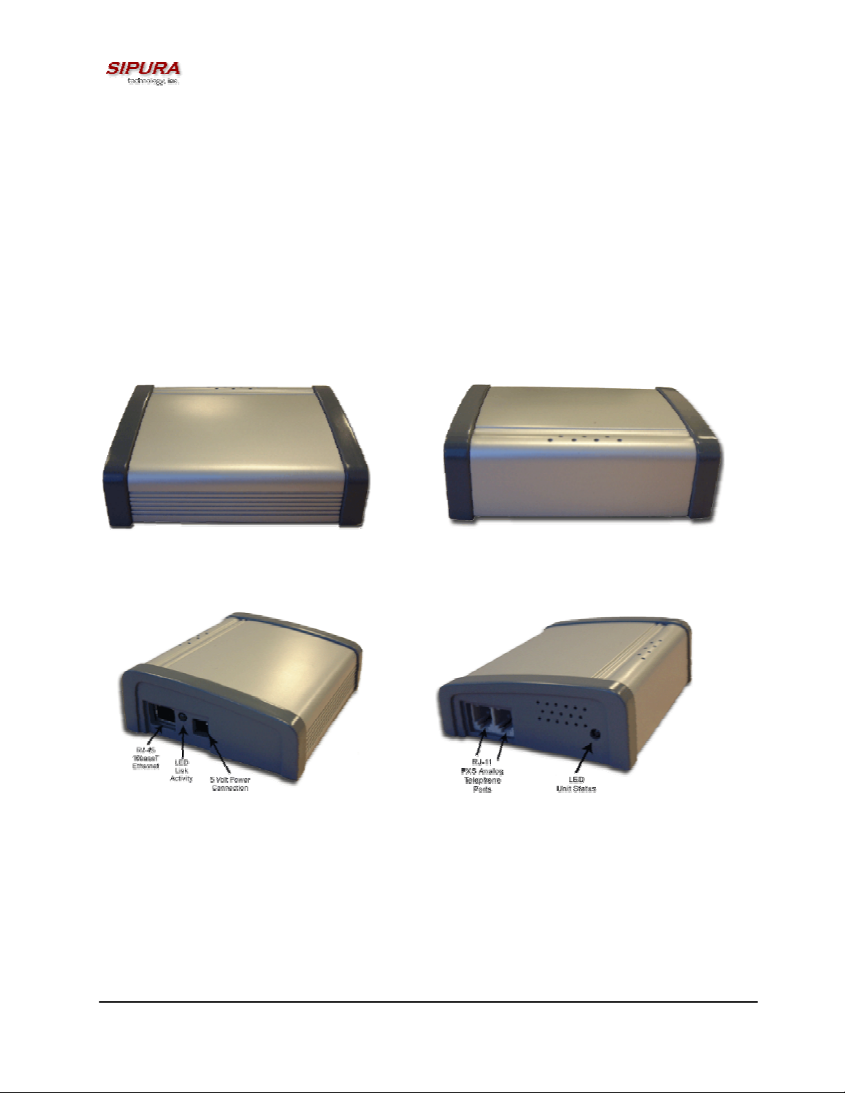
1.1. SPA-2000 Hardware Overview
The SPA-2000 has one of the smallest form factors on the market. It can be installed in minutes as a
table-top or wall mount CPE device. Figures Figure 1, Figure 2, Figure 3 and Figure 5 show the front,
rear, left side and right side of the SPA-2000, respectively.
Figure 1 – SPA-2000 Front
Figure 3 – SPA-2000 Left Side
The SPA-2000 has the following interfaces for networking, power and visual status indication:
1. Two (2) RJ-11 Type Analog Telephone Jack Interfaces (Figure 4, above):
These interfaces accept standard RJ-11 telephone connectors. An Analog touchtone telephone or
fax machine may be connected to either interface. If the service supports only one incoming line, the
analog telephone or fax machine should be connected to port one (1) of the SPA-2000. Port one (1)
is the outermost telephone port on the SPA-2000 and is labeled “Phone 1.”
Figure 2 – SPA-2000 Rear
Figure 4 – SPA-2000 Right Side
2. One LED for Unit Status (Figure 4, above):
© 2003 Sipura Technology, Inc Proprietary (See Copyright Notice on Page 2)
4
Page 5

This LED indicates status via the following behaviors:
ON – LED remains solid on
OFF – LED remains solid off
LONG (Long On) – 3.0s on, 1s off continuously
FAST – 0.125s on, 0.125s off continuously
SLOW – 0.5s on, 0.5s off continuously
VSLO (Very Slow) – 1.0s on, 1.0s off continuously
HB (Heart Beat) – 0.125s on, 0.125s off, 0.125s on, 1s off continuously
3. One Ethernet 10baseT RJ-45 Jack Interface (
Figure , above):
This interface accepts a standard or crossover Ethernet cable with standard RJ-45 connector. For
optimum performance, Sipura Technology recommends that a Category 5 cable or greater be used in
conjunction with the SPA-2000.
4. One LED for Data Link and Activity (
Figure , above):
This LED indicates status via the following behaviors:
ON – LED remains solid on
OFF – LED remains solid off
FAST – 0.125s on, 0.125s off continuously
SLOW – 0.5s on, 0.5s off continuously
Variable Blink – LED blinks according to packet traffic activity
5. One 5 Volt Power Adapter Interface (
Figure , above)
This interface accepts the SPA-2000 power adapter that came with the unit. Sipura Technology does
not support the use of any other power adapters other then the power adapter that was shipped with
the SPA-2000 unit.
1.1.1. Status LED Description:
The SPA-2000 Status LED is used to indicate the current operation status of the SPA unit. The state
is represented by a special blinking pattern of the Status LED (next to the RJ-11 ports on the right
side of the device). The below table describes the various modes and behaviors of the SPA-2000 in
relation to the Status LED and the handset behavior.
Status Description LED
Blink
Rate
Normal Operation – Both Lines on hook OFF Normal
Normal Operation – Either line off hook ON Normal
Downloading new firmware SLOW Silent
Writing firmware to flash FAST Silent
Looking for DHCP Server SLOW Silent
No DHCP Server SLOW Silent
IP Address Conflict SLOW Silent
Default Handset
Behavior
© 2003 Sipura Technology, Inc Proprietary (See Copyright Notice on Page 2)
5
Page 6

Unknown DHCP Error SLOW Silent
Note: The Link LED will blink on transmit and receive (TX/RX) of packets. The LED will display solid
off if no link is available. The LED will display solid on if link is up but no TX/RX activity is present.
Important Warning: Do not disrupt the power to the SPA-2000 while the Status LED is blinking FAST.
2. Installation Overview
Please check to make sure that you have the following package contents:
1. Sipura Phone Adapter Unit
2. Ethernet Cable
3. SPA-2000 QuickGuide
4. 5 Volt Power Adapter
You will also need:
1. One or Two Analog Touch Tone Telephones (or Fax Machine)
2. Access to an IP Network via an Ethernet Connection
Please observe the following steps to install the SPA-2000.
From the Left Side of the SPA-2000:
1. Insert a standard RJ-45 Ethernet cable (included) into the LAN port.
2. Insert the power adapter cable into the 5V power adapter cable receptacle.
Ensure that the power adapter jack is snugly attached to the SPA.
From the Right Side of the SPA-2000:
1. Insert a standard RJ-11 telephone cable into the Phone 1 port.
2. Connect the other end of the cable to an analog telephone or fax machine.
3. Insert a standard RJ-11 telephone cable into the Phone 2 port (Optional).
4. Connect the other end of the cable to an analog telephone or fax machine.
Note: Do not connect RJ-11 telephone cable from the SPA to the wall jack
to prevent any chance of connection to the circuit switched telco network.
You may now insert the plug end of the power adapter into a live power outlet which will power up the
SPA-2000.
3. Software Configuration
3.1.1.1. Firmware Upgrade
The SPA-2000 is firmware upgradeable via TFTP or via an executable PC program obtained from
Sipura Technology or an authorized distributor/reseller of Sipura Technology products.
Please contact the company from whom you purchased your SPA-2000 for access to Sipura
Technology firmware upgrades.
Firmware Upgrade via TFTP:
Firmware designed for TFTP upgrades are released as single binary files, which contain all the
modules pertaining to any one release version. By convention, the firmware loads are named with the
extension “.bin” (e.g. spa.bin)
The SPA-2000 can be configured to upgrade to a specific version, possibly staging through
intermediate releases, if necessary. This process can be automated for a pool of devices through
configuration profile parameters.
© 2003 Sipura Technology, Inc Proprietary (See Copyright Notice on Page 2)
6
Page 7

Alternatively, an individual SPA-2000 can be directed to perform an upgrade to a specific firmware
load via its built-in web server interface.
Firmware upgrades are attempted only when the SPA-2000 is idle, since they trigger a software
reboot.
Firmware Upgrade via PC Utility Program:
From time to time, Sipura Technology will make available a PC executable file that will facilitate the
upgrade of a SPA-2000. In order to upgrade a device via this method, the end user must have
administrative permission (via password protected log-in) to perform this upgrade.
Once the user has obtained the proper firmware upgrade executable, the user simply runs the
program from a file location on their local PC. The PC program walks the user through the upgrade
process via a graphical user interface. Generally, the entire upgrade process should take no more
than five minutes to complete.
Please note: Some end-users who have obtained their SPA-2000 directly from a service provider will
never need to manually upgrade their device. Via the remote upgrade process, Sipura Technology
provides capability for the SPA-2000 to be maintained from a remote location (e.g. a service provider
network server), using the Internet connection of the end-user as the conduit through which profile
updates and firmware upgrades are performed.
3.2. IVR Interface
Administrators and/or users can check (read) and set (write) basic network configuration settings via
a touchtone telephone connected to one of the RJ-11 phone ports of the SPA-2000.
Please Note: Service Providers offering service using the SPA-2000 may restrict, protect or turn off
certain aspects of the unit’s IVR and web configuration capabilities.
The Interactive Voice Response (IVR) capabilities of the SPA are designed to give the administrator
and/or user basic read/write capabilities such that the unit can attain basic IP network connectivity
and, if allowed by the service provider, the more advanced browser-based configuration menu may
be accessed.
3.2.1. IVR Conventions:
1. The SPA IVR uses the following conventions: By factory default, there is no password. No
password authentication is required for all the IVR settings. If Administrator password is set,
password authentication will be prompted for certain IVR settings. See 3.3.2 for detailed information
about administrator password.
Please note: The Administrator and User passwords may only be set via the SPA-2000 web
interface.
To input the password using the phone keypad, the following translation convention applies:
o To input: A, B, C, a, b, c -- press ‘2’
o To input: D, E, F, d, e, f -- press ‘3’
o To input: G, H, I, g, h, i -- press ‘4’
o To input: J, K, L, j, k, l -- press ‘5’
o To input: M, N, O, m, n, o -- press ‘6’
o To input: P, Q, R, S, p, q, r, s -- press ‘7’
o To input: T, U, V, t, u, v -- press ‘8’
© 2003 Sipura Technology, Inc Proprietary (See Copyright Notice on Page 2)
7
Page 8

o To input: W, X, Y, Z, w, x, y, z -- press ‘9’
o To input all other characters in the administrator password, press ‘0’
Note: This translation convention only applies to the password input.
For example: to input password “test#@1234” by phone keypad, you need to press the following
sequence of digits: 8378001234.
2. After entering a value, press the # (pound) key to indicate end of input.
o To Save value, press ‘1’
o To Review the value, press ‘2’
o To Re-enter the value, press ‘3’
o To Cancel the value entry and return to the main configuration menu, press ‘
Please Note:
o The final ‘#’ key will not be counted as part of the value.
o Saved settings will take effect when the telephone is hung-up and if necessary, the SPA-
2000 will automatically reboot.
3. After one minute of inactivity, the unit times out. The user will need to re-enter the configuration
menu from the beginning by pressing * * * *.
4. If, while entering a value (like an IP address), you decide to exit without entering any changes, you
may do so by pressing the * (star) key twice within a half second window of time. Otherwise, the
entry of the * (star) key will be treated as a dot (decimal point).
Example:
To enter an IP address, use numbers 0 – 9 on the telephone key pad. Use the * (star) key to enter a
decimal point.
To enter the following IP address value: 192.168.2.215
A. Use the touchtone key pad to enter: 192*168*2*215#
B. When prompted, enter 1 to save setting to configuration.
C. Hang-up the phone to cause setting to take effect.
- or -
D. Enter the value of the next setting category to modify . . .
*’ (star)
5. Hang-up the phone to cause all settings to take effect.
3.2.2. SPA-2000 Interactive Voice Response (IVR) Menu:
IVR Action IVR Menu Choice Parameter(s) Notes:
Enter IVR Menu
* * * *
Check DHCP
© 2003 Sipura Technology, Inc Proprietary (See Copyright Notice on Page 2)
100
None Ignore SIT or other tones
until you hear, “Sipura
configuration menu.
Please enter option
followed by the pound key
or hang-up to exit.”
None IVR will announce if DHCP
in enabled or disabled.
8
Page 9

Enable/Disable DHCP
Check IP Address
Set Static IP Address
Check Network Mask
Set Network Mask
Check Static Gateway IP
Address
101
110
111
120
121
130
Enter 1 to enable
Enter 0 to disable
None IVR will announce the
current IP address of SPA.
Enter IP address
using numbers on
the telephone key
pad. Use the *
DHCP must be “Disabled”
otherwise you will hear,
“Invalid Option,” if you try
to set this value.
(star) key when
entering a decimal
point.
None IVR will announce the
current network mask of
SPA.
Enter value using
numbers on the
telephone key pad.
Use the * (star) key
DHCP must be “Disabled”
otherwise you will hear,
“Invalid Option,” if you try
to set this value.
when entering a
decimal point.
None IVR will announce the
current gateway IP
address of SPA.
Set Static Gateway IP
Address
Check MAC Address
Check Firmware Version
Enable/Disable Web
Server of SPA
Manual Reboot of Unit
Factory Reset of Unit
WARNING:
131
140
150
7932
732668
73738
Enter IP address
using numbers on
the telephone key
pad. Use the *
DHCP must be “Disabled”
otherwise you will hear,
“Invalid Option,” if you try
to set this value.
(star) key when
entering a decimal
point.
None IVR will announce the
MAC address of SPA in
hex string format.
None IVR will announce the
version of the firmware
running on the SPA.
Enter 1 to enable
Requires Password
Enter 0 to disable
None After you hear “Option
Successful,” hang-up. Unit
will reboot automatically.
Enter 1 to confirm
Enter * (start) to
cancel operation
SPA will prompt for
confirmation. After
confirming, you will hear
“Option Successful.” Hang-
© 2003 Sipura Technology, Inc Proprietary (See Copyright Notice on Page 2)
9
Page 10

ALL SETTINGS WILL BE LOST!
up. Unit will reboot and all
configuration parameters
will be reset to factory
default values.
Note: If the Administrator password is not set, the items marked with “Requires Password” will not
require a password.
3.3. SPA Web Interface
The SPA provides a built-in web server. Convenient configuration and administration can be
performed through an integral web interface.
3.3.1. Web Interface Conventions
The SPA uses the following conventions with the web administration capabilities:
o The SPA-2000 web administration supports two privilege levels: Administrator and User. To
use the User privilege, simply point a web browser at the IP address of the SPA-2000; to use
the administrator privilege, use URL http://IP_Address_Of_SPA/admin
information about administration privileges.
o Version 1.0 of the SPA supports Internet Explorer 5.5 and above and Netscape 7.0 and
above.
o The web configuration pages can be password protected. See 3.3.2 for more information
about password protect.
/. See 3.3.2 for more
o The user name of web Administrator is : admin
o The user name of web User is : user
o Note: The user names for both administrator and User are fixed and cannot be
changed.
o After making changes to SPA-2000 configuration parameters, pressing “Submit All
Changes” button will apply all the changes and if necessary, automatically reboot the device.
Multiple changes may be made on multiple page tabs of the web interface at the same time.
Pressing “Submit All Changes” will apply all the modifications.
Important Note: switching between page tabs won’t apply the changes to SPA-2000, The
only way to apply the changes is to press the “Submit All Changes” button.
o If the “Undo All Changes” button is clicked, any modifications to profile parameters on any and
all pages will be reset back to their original values before modification.
NOTE: Pressing the “Undo All Changes” has no effect on the SPA-2000; it will only reset the
values on the web page.
3.3.2. Administration Privileges
The SPA-2000 supports two levels of administration privileges: Administrator and User, both
privileges can be password protected.
Important note: by factory default, there are no passwords assigned for both Administrator and User.
The Administrator has the privilege to modify all web profile parameters and can also modify the
passwords of both Administrator and User. A User only has the privilege to access part of the web
© 2003 Sipura Technology, Inc Proprietary (See Copyright Notice on Page 2)
10
Page 11

profile parameters. The parameter group that the User can access is specified by the Administrator,
which can only be done through provisioning the SPA-2000 via the TFTP process.
To access the Administrator level privilege, use the following URL: http://IP_Address_Of_SPA/admin
If the password has been set for Administrator, the browser will prompt for Administrator
authentication. The username for Administrator is “admin” and cannot be changed.
To access the User level privilege, use URL: http://IP_Address_Of_SPA/
set for User, the browser will prompt for User authentication. The username for User is “user” and
cannot be changed.
When browsing Administrator pages, one can switch to User privileges by clicking the link “User
Login”. (Note: if User password was set, the browser will prompt for User authentication when you
click the “User Login” link). Conversely, from the User pages you can switch to Administrator privilege
by clicking the link “Admin Login.” Authentication is needed if the Administrator password has been
previously set.
Warning: Switching between the User and Administrator will discard the uncommitted changes that
have already been made on the web pages.
. If the password has been
3.3.3. Basic and Advanced Views
The web configuration interface provides a Basic and an Advanced view from which the various
configuration parameters can be accessed. The SPA Provisioning tab is only visible from the
Advanced Administrator view of the web interface.
Warning: Switching between the basic and advanced view will discard the uncommitted changes that
have already been made on the web pages.
/.
© 2003 Sipura Technology, Inc Proprietary (See Copyright Notice on Page 2)
11
Page 12
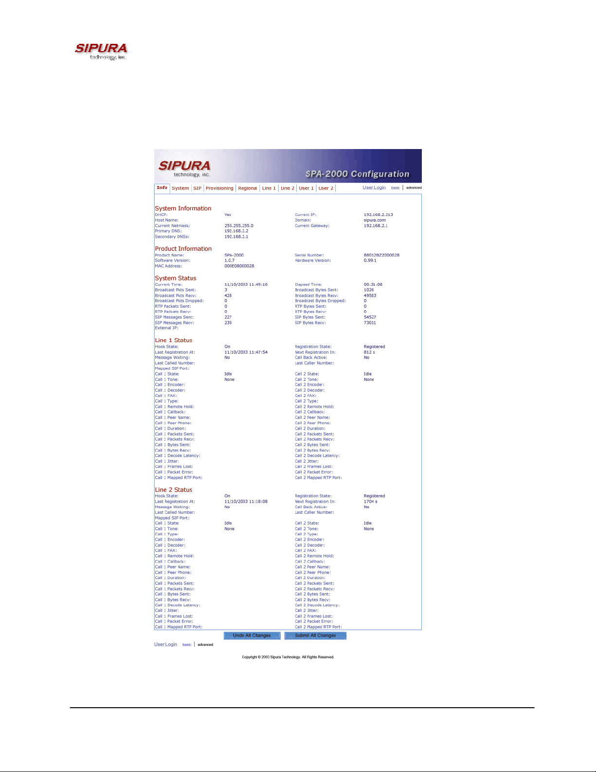
3.3.4. SPA-2000 Web Page Configuration Default Values
The following figures depict the default values and web page locations of the SPA-2000 web
administration and configuration pages. The SPA-2000 Administrator Log-in, Advanced screen
settings are shown below.
Figure 1 – SPA-2000 Information Web Page (Advanced Admin View)
© 2003 Sipura Technology, Inc Proprietary (See Copyright Notice on Page 2)
12
Page 13
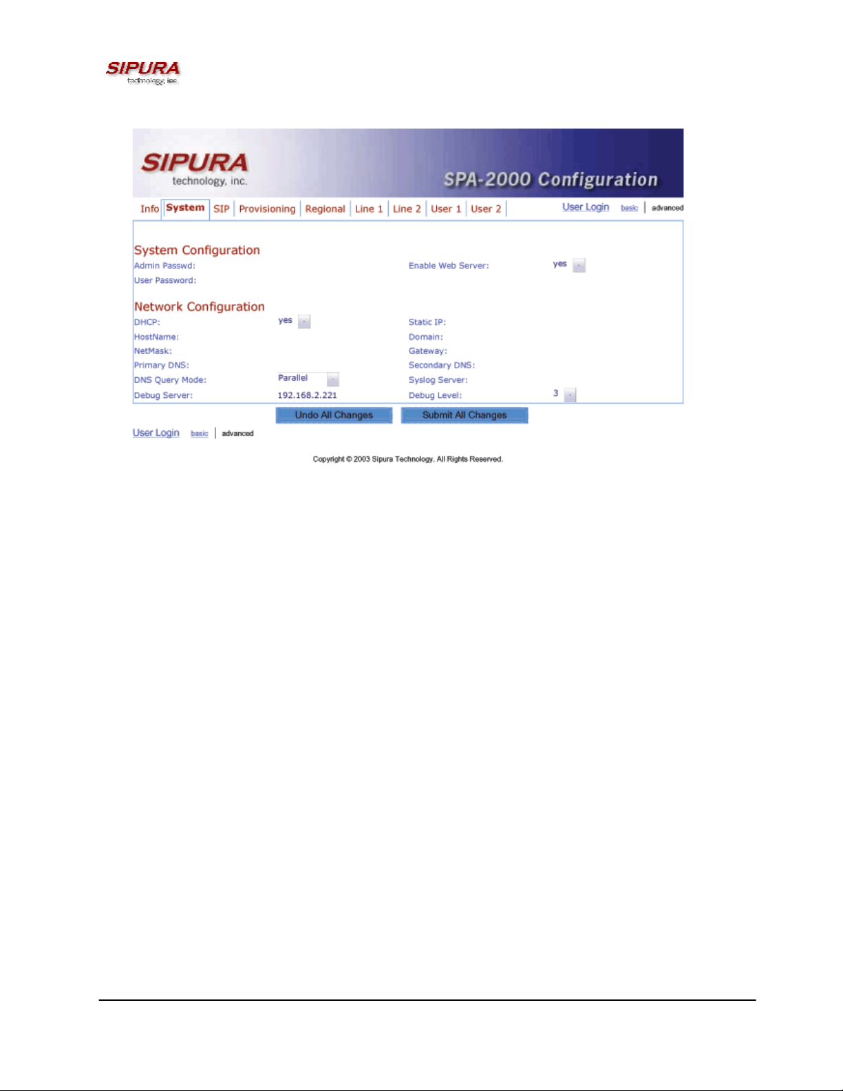
Figure 2 – SPA-2000 System Configuration Web Page (Advanced Admin View)
© 2003 Sipura Technology, Inc Proprietary (See Copyright Notice on Page 2)
13
Page 14
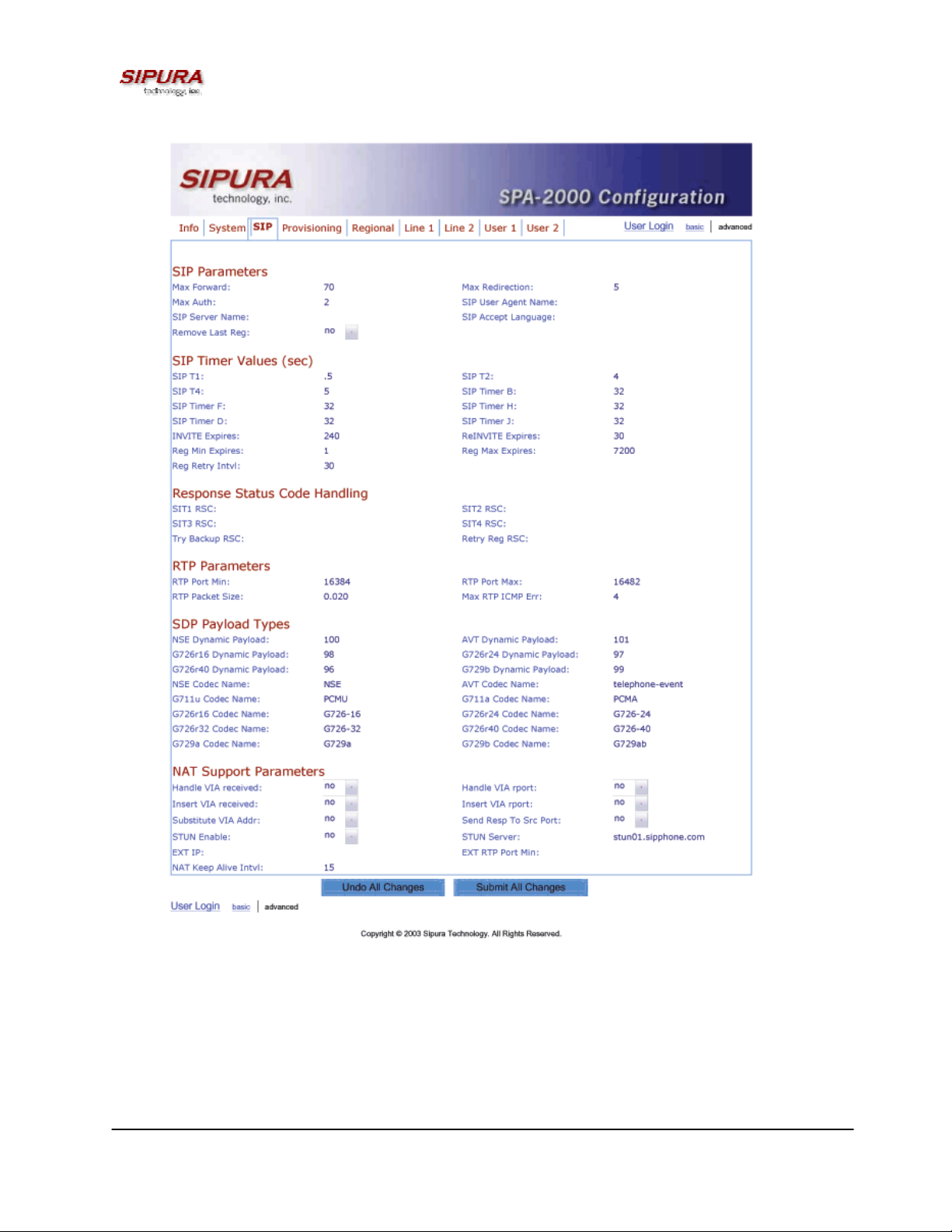
Figure 3 – SPA-2000 SIP Configuration Web Page (Advanced Admin View)
© 2003 Sipura Technology, Inc Proprietary (See Copyright Notice on Page 2)
14
Page 15
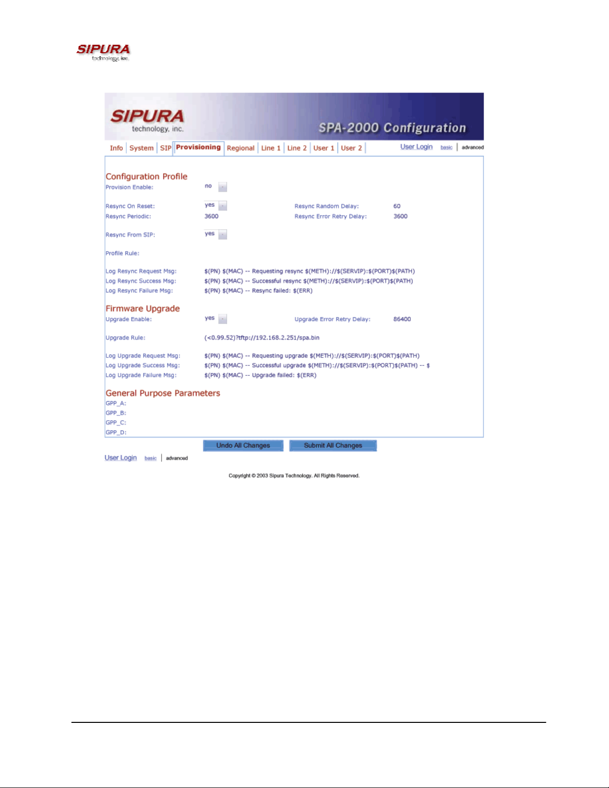
Figure 4 – SPA-2000 Provisioning Configuration Web Page (Advanced Admin View)
© 2003 Sipura Technology, Inc Proprietary (See Copyright Notice on Page 2)
15
Page 16
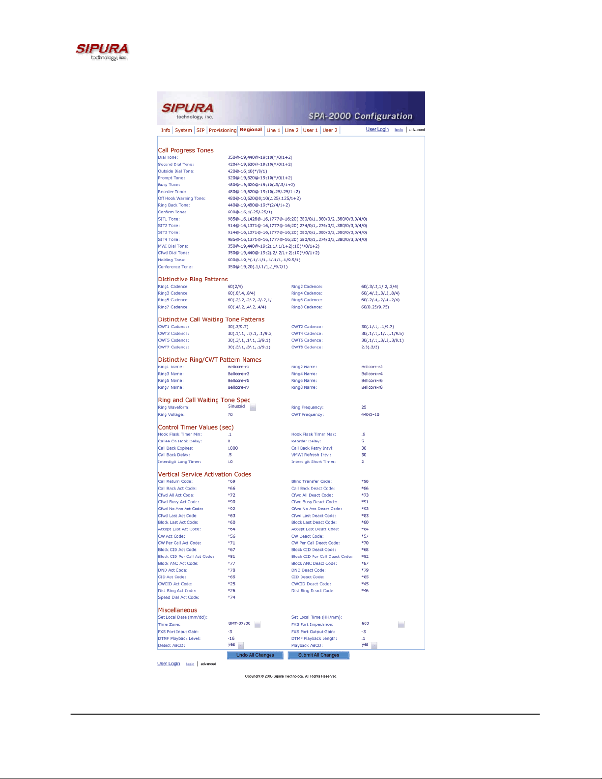
Figure 5 – SPA-2000 Regional Configuration Web Page (Advanced Admin View)
© 2003 Sipura Technology, Inc Proprietary (See Copyright Notice on Page 2)
16
Page 17

Figure 6 – SPA-2000 Line 1 Configuration Web Page (Line 2 Is Identical)
© 2003 Sipura Technology, Inc Proprietary (See Copyright Notice on Page 2)
17
Page 18

Figure 7 – SPA-2000 User 1 Configuration Web Page (User 2 Is Identical)
© 2003 Sipura Technology, Inc Proprietary (See Copyright Notice on Page 2)
18
Page 19

3.4. Configuration Parameters
3.4.1. System Parameters
System Configuration
Parameter Name Description Default
Admin Password The password for administrator
User Password The password for User
Enable Web Server Enable/disable web server of SPA
This feature should only be used on firmware version 1.0.9 or later.
Network Configuration
Parameter Name Description Default
DHCP Enable/Disable DHCP Yes
Host Name Host Name of SPA
Domain Name The network domain of SPA
Static IP Static IP address of SPA, which will take effect if DHCP is
disabled
NetMask The NetMask used by SPA when DHCP is disabled 255.255.255.
Gateway The default gateway used by SPA when DHCP is disabled 0.0.0.0
Primary DNS DNS server used by SPA in addition to DHCP supplied DNS
servers if DHCP is enabled; when DHCP is disabled, this will
be the primary DNS server.
Secondary DNS DNS server used by SPA in addition to DHCP supplied DNS
servers if DHCP is enabled; when DHCP is disabled, this will
be the secondary DNS server.
DNS Query Mode Do parallel or sequential DNS Query Parallel
Syslog Server Specify the syslog server name and port. This feature
specifies the server for logging SPA system information and
critical events.
Debug Server The debug server name and port. This feature specifies the
server for logging SPA debug information. The level of
detailed output depends on the debug level parameter
setting.
Debug Level The higher the debug level, the more debug information will
be generated. Zero (0) means no debug information will be
generated.
Yes
0.0.0.0
0
0.0.0.0
0.0.0.0
0
Notes:
- Parallel DNS query mode: SPA-2000 will send the same request to all the DNS servers at the
same time when doing a DNS lookup, the first incoming reply will be accepted by SPA-2000.
- To log SIP messages, Debug Level must be set to at least 2.
- If both Debug Server and Syslog Server are specified, syslog messages are also logged to the
Debug Server.
3.4.2. Provisioning Parameters
Provisioning operations are gated by the Provision_Enable parameter.
Parameter Name Description Default
Provision Enable Master enable for configuration profile resync operations Yes
© 2003 Sipura Technology, Inc Proprietary (See Copyright Notice on Page 2)
19
Page 20

Resync On Reset Resyncs configuration profile from configuration server
Yes
whenever the SPA-2000 resets.
Resync Random
Spread interval for resync requests 2
Delay
Resync Periodic Resyncs configuration profile periodically after reset. 3600
Resync Error
Retry interval following resync failure 3600
Retry Delay
Resync From SIP Enables resync of configuration profile from a SIP command. Yes
Profile Rule Configuration profile URL script. /spa.cfg
Log Resync
Syslog message generated when attempting a resync
Request Msg
Log Resync
Syslog message generated after a successful resync
Success Msg
Log Resync
Syslog message generated after a failed resync
Failure Msg
GPP A General purpose parameter empty
GPP B General purpose parameter empty
GPP C General purpose parameter empty
GPP D General purpose parameter empty
Note: In a customized SPA-2000, the profile rule would point to a service provider’s server.
3.4.3. Upgrade Parameters
Parameter Name Description Default
Upgrade Enable Master enable for firmware upgrade operations Yes
Upgrade Error
Retry Delay
Upgrade Rule Upgrade script. empty
Log Upgrade
Request Msg
Log Upgrade
Success Msg
Log Upgrade
Failure Msg
Note: In a customized SPA-2000, the upgrade rule would point to a service provider’s server.
Retry interval following upgrade failure 3600
Syslog message generated when attempting an upgrade
Syslog message generated after a successful upgrade
Syslog message generated after a failed upgrade
3.4.4.
Protocol Parameters
Parameter Name Description Default
Max Forward SIP Max-Forward value. Range: 1 – 255 70
Max Redirection Number of times to allow an INVITE to be redirected by a 3xx
5
response to avoid an infinite loop.
Note: This parameter currently has no effect: there is no limit on number of
redirection.
Max Auth Maximum number of times a request may be challenged (0-255) 2
SIP User Agent
Name
SIP Server Name Server Header to used by the unit in responses to inbound
User-Agent Header to be used by the unit in outbound requests.
If empty, the header is not included.
responses. If empty, the header is not included.
Sipura/
$version
Sipura/
$version
© 2003 Sipura Technology, Inc Proprietary (See Copyright Notice on Page 2)
20
Page 21

SIP Accept Language Accept-Language Header to be used by the unit.
If empty, the header is not included.
Remove Last Reg Remove last registration before registering a new one if value is
no
different one.
SIP T1 RFC 3261 T1 value (RTT Estimate). Range: 0 – 64 sec .5
SIP T2 RFC 3261 T2 value (Maximum retransmit interval for non-INVITE
4
requests and INVITE responses). Range: 0 – 64 sec
SIP T4 RFC 3261 T4 value (Maximum duration a message will remain in
5
the network). Range: 0 – 64 sec
SIP Timer B INVITE time out value. Range: 0 – 64 sec 32
SIP Timer F Non-INVITE time out value. Range: 0 – 64 sec 32
SIP Timer H INVITE final response time out value. Range: 0 – 64 sec 32
SIP Timer D ACK hang around time. Range: 0 – 64 sec 32
SIP Timer J Non-INVITE response hang around time. Range: 0 – 64 sec 32
INVITE Expires INVITE request Expires header value in sec. 0 = do not include
Expires header in INVITE. Range: 0 – (2
ReINVITE Expires ReINVITE request Expires header value in sec. 0 = do not
include Expires header in the request. Range: 0 – (2
31
– 1)
31
– 1)
Reg Min Expires Minimum registration expiration time allowed from the proxy in
180
30
1
the Expires header or as a Contact header parameter. If proxy
returns something less this value, then the minimum value is
used.
Reg Max Expires Maximum registration expiration time allowed from the proxy in
7200
the Min-Expires header. If value is larger than this, then the
maximum value is used
Reg Retry Intvl Interval to wait before the SPA retries registration again after
30
encountering a failure condition during last registration
SIT1 RSC1 SIP response status code to INVITE on which to play the SIT1
Tone
SIT2 RSC1 SIP response status code to INVITE on which to play the SIT2
Tone
SIT3 RSC1 SIP response status code to INVITE on which to play the SIT3
Tone
SIT4 RSC1 SIP response status code to INVITE on which to play the SIT4
Tone
Try Backup RSC SIP response status code on which to retry a backup server for
the current request
Retry Reg RSC Interval to wait before the SPA retries registration again after
30
encountering a failure condition during last registration
RTP Port Min2 Minimum port number for RTP transmission and reception 16384
RTP Port Max2 Maximum port number for RTP transmission and reception 16482
RTP Packet Size Packet size in sec. Valid values must be multiple of 0.01s.
0.02
Range: 0.01 – 0.16
Notes:
1. Reorder or Busy Tone will be played by default for all unsuccessful response status code
2. <RTP Port Min> and <RTP Port Max> should define a range that contains at least 4 even number
ports, such as 100 – 106
3.4.4.1. Dynamic Payload Types
Parameter Name Description Default
© 2003 Sipura Technology, Inc Proprietary (See Copyright Notice on Page 2)
21
Page 22

NSE Dynamic Payload
AVT Dynamic Payload
G726r16 Dynamic Payload
G726r24 Dynamic Payload
G726r40 Dynamic Payload
G729b Dynamic Payload
1,2
NSE dynamic payload type 100
1,2
AVT dynamic payload type 101
1,2
G726-16 dynamic payload type 98
1,2
G726-24 dynamic payload type 97
1,2
G726-40 dynamic payload type 96
1,2
G729b dynamic payload type 99
Notes:
1. Valid range is 96 – 127
2. The configured dynamic payloads are used for outbound calls only where the SPA-2000 presents
the SDP offer. For inbound calls with a SDP offer, SPA-2000 will follow the caller’s dynamic payload
type assignments
3.4.4.2. SDP Audio Codec Names
Parameter Name Description Default
NSE Codec Name NSE Codec name used in SDP NSE
AVT Codec Name AVT Codec name used in SDP telephone-event
G711a Codec Name G711a Codec name used in SDP PCMA
G711u Codec Name G711u Codec name used in SDP PCMU
G726r16 Codec Name G726-16 Codec name used in SDP G726-16
G726r24 Codec Name G726-24 Codec name used in SDP G726-24
G726r32 Codec Name G726-32 Codec name used in SDP G726-32
G726r40 Codec Name G726-40 Codec name used in SDP G726-40
G729a Codec Name G729a Codec name used in SDP G729a
G729b Codec Name G729b Codec name used in SDP G729ab
Notes:
1. SPA-2000 uses the configured codec names in its outbound SDP
2. SPA-2000 ignores the codec names in incoming SDP for standard payload types (0 – 95).
3. For dynamic payload types, SPA-2000 identifies the codec by the configured codec names.
Comparison is case-insensitive.
3.4.4.3. NAT Support
Parameter Name Description Default
Handle_VIA_received If set to “yes”, the SPA will process the “received” parameter
No
in the VIA header inserted by the server in a response to any
one of its request. Else the parameter is ignored.
Handle_VIA_rport If set to “yes”, the SPA will process the “rport” parameter in
No
the VIA header inserted by the server in a response to any
one of its request. Else the parameter is ignored.
Insert VIA received Insert received parameter in VIA header in SIP responses if
No
received from IP and VIA sent-by IP differ
Insert VIA rport Insert rport parameter in VIA header in SIP responses if
No
received-from port and VIA sent-by port differ
Substitute VIA addr Use nat-mapped IP:port values in VIA header No
Send Resp To Src Port Send response to the request source port instead of the VIA
No
sent-by port
STUN Server STUN server to contact for NAT mapping discovery
STUN Enable Enable the use of STUN to discover NAT mapping No
© 2003 Sipura Technology, Inc Proprietary (See Copyright Notice on Page 2)
22
Page 23

Ext IP External IP address to substitute for the actual IP address of
the unit in all outgoing SIP messages. If “0.0.0.0” is specified,
no IP address substitution is performed.
Ext RTP Port Min External port mapping of <RTP Port Min>. If this value is non-
zero, the RTP port number in all outgoing SIP messages is
substituted by the corresponding port value in the external
RTP port range.
NAT Keep Alive Intvl Interval between sending NAT-mapping keep alive message
in sec
Notes:
0.0.0.0
0
15
3.4.5. Line 1 and Line 2 Parameters
Per line parameter tags must be appended with [1] or [2] (corresponding to lines 1 or 2) in the
configuration profile. It is omitted below for readability.
3.4.5.1. User Account Information
Parameter Name Description Default
Line Enable Enable this line for service Yes
SIP Port SIP message listening port and transmission port 5060
Ext SIP Port External port to substitute for the actual SIP port of
the unit in all outgoing SIP messages. If “0” is
specified, no SIP port substitution is performed.
SIP TOS/DiffServ
Value
RTP TOS/DiffServ
Value
NAT Mapping Enable Enable the use of externally mapped of IP address
NAT Keep Alive
Enable
NAT Keep Alive Msg Contents of the keep-alive message to be sent to a
NAT Keep Alive Dest Destination to send NAT keep alive messages to. If
SIP Debug Option None, 1-line, full, exclude OPTIONS, exclude
Proxy SIP Proxy Server for all outbound requests
Use Outbound Proxy Enable the use of <Outbound Proxy>. If set to “no”,
Outbound Proxy SIP Outbound Proxy Server where all outbound
© 2003 Sipura Technology, Inc Proprietary (See Copyright Notice on Page 2)
TOS/DiffServ field value in UDP IP Packets
carrying a SIP Message
TOS/DiffServ field value in UDP IP Packets
carrying a RTP data
and SIP/RTP ports in SIP messages. The mapping
may be discovered by any of the supported
methods.
If set to “yes”, the configured <NAT Keep Alive
Msg> is sent periodically every <NAT Keep Alive
Intvl> seconds.
given destination periodically to maintain the
current NAT-mapping. It could be an empty string.
If value is $NOTIFY, a NOTIFY message is sent as
keep alive. If value is $REGISTER, a REGISTER
message w/o Contact is sent.
value is $PROXY, it will be sent to the current
proxy or outbound proxy
REGISTER, exclude NOTIFY, …
<Outbound Proxy> and <Use OB Proxy in Dialog)
is ignored.
requests are sent as the first hop.
0
0x68
0xb8
No
No
$NOTIFY
$PROXY
none
No
No
23
Page 24

Use OB Proxy In
Dialog
Whether to forcer SIP requests to be sent to the
outbound proxy within a dialog. Ignored if <Use
Outbound Proxy> is “no” or <Outbound Proxy> is
empty
Register Enable periodic registration with the <Proxy>. This
parameter is ignored if <Proxy> is not specified.
Make Call Without
Reg
Allow making outbound calls without successful
(dynamic) registration by the unit. If “No”, dial tone
will not play unless registration is successful
Ans Call Without Reg Allow answering inbound calls without successful
(dynamic) registration by the unit
Register Expires1 Expires value in sec in a REGISTER request. SPA
will periodically renew registration shortly before
the current registration expired. This parameter is
ignored if <Register> is “no”. Range: 0 – (2
31
– 1)
sec
Use DNS SRV Whether to use DNS SRV lookup for Proxy and
Outbound Proxy
Display Name Subscriber’s display name to appear in caller-id
User ID Subscriber’s user-id. Usually a E.164 number
Password Subscriber’s a/c password
Auth ID Subscriber’s authentication ID
Use Auth ID If set to “yes”, the pair <Auth ID> and <Password>
are used for SIP authentication. Else the pair <User
ID> and <Password> are used.
Yes
Yes
No
No
3600
No
No
Notes:
1. If proxy responded to REGISTER with a smaller Expires value, the SPA will renew registration
based on this smaller value instead of the configured value. If registration failed with an “Expires too
brief” error response, the SPA will retry with the value given in the Min-Expires header in the error
response.
3.4.5.2. Supplementary Services Enable
The SPA-2000 provides native support of a large set of enhanced or supplementary services. All of
these services are optional. The parameters listed in the following table are used to enable or disable
a specific supplementary service. A supplementary service should be disabled if a) the user has not
subscribed for it, or b) the Service Provider intends to support similar service using other means than
relying on the SPA-2000.
Parameter Name Description Default
CW Serv Enable Call Waiting Service Yes
Block CID Serv Enable Block Caller ID Service Yes
Block ANC Serv Enable Block Anonymous Calls Service Yes
Dist Ring Serv Enable Distinctive Ringing Service Yes
Cfwd All Serv Enable Call Forward All Service Yes
Cfwd Busy Serv Enable Call Forward Busy Service Yes
Cfwd No Ans Serv Enable Call Forward No Answer Service Yes
Cfwd Sel Serv Enable Call Forward Selective Service Yes
DND Serv Enable Do Not Disturb Service Yes
CID_Serv Enable Caller ID Service Yes
CWCID Serv Enable Call Waiting Caller ID Service Yes
© 2003 Sipura Technology, Inc Proprietary (See Copyright Notice on Page 2)
24
Page 25

Call Return Serv Enable Call Return Service Yes
Call Back Serv Enable Call Back Service Yes
Three Way Call Serv1 Enable Three Way Calling Service Yes
Three Way Conf
1,2
Serv
Attn Transfer Serv
Unattn Transfer Serv Enable Unattended (Blind) Call Transfer
Enable Three Way Conference Service Yes
1,2
Enable Attended Call Transfer Service Yes
Yes
Service
MWI Serv3 Enable MWI Service Yes
VMWI Serv Enable VMWI Service (FSK) Yes
Block Last Serv Enable Block Last Call Service Yes
Accept Last Serv Enable Accept Last Call Service Yes
Cfwd Last Serv Enable Forward Last Call Service Yes
Speed Dial Serv Enable Speed Dial Service Yes
Notes:
1. Three Way Calling is required for Three Way Conference and Attended Transfer.
2. Three Way Conference is required for Attended Transfer.
3. MWI is available only if a Voice Mail Service is set-up in the deployment.
3.4.5.3. Audio Settings
Parameter Name Description Default
Preferred Codec Select a preferred codec for all calls. However, the
G711u
actual codec used in a call still depends on the
outcome of the codec negotiation protocol.
Use Pref Codec Only Only use the preferred codec for all calls. The call will
No
fail if the far end does not support this codec.
LBR Codec Enable Enable of the use of Low Bit Rate Codec, such as
Yes
G726 and G729. If set to “no”, only G711u or G711a
codec will be used in all calls on this line
Silence Supp Enable Enable silence suppression so that silent audio
No
frames are not transmitted
Echo Canc Enable Enable the use of echo canceller Yes
Echo Canc Adapt
Enable echo canceller to adapt Yes
Enable
Echo Supp Enable Enable the use of echo suppressor. If <Echo Canc
Yes
Enable> is “no”, this parameter is ignored
FAX Detect Enable Enable detection of FAX tone. Ignored if <FAX
Yes
Passthru Enable> is “no”
FAX Passthru Enable Enable FAX pass-through support Yes
DTMF Tx Method Method to transmit DTMF signals to the far end:
Auto
Inband = Send DTMF using the audio path; INFO =
Use the SIP INFO method, AVT = Send DTMF as
AVT events; Auto = Use In-band or AVT (RFC 2833)
based on outcome of codec negotiation
FAX Passthru Codec Codec to use for fax pass-through G711u
FAX Codec
Symmetric
Force unit to use symmetric codec during FAX passthrough
yes
Notes:
© 2003 Sipura Technology, Inc Proprietary (See Copyright Notice on Page 2)
25
Page 26

3.4.5.4. Dial Plan
Parameter Name Description Default
Dial Plan Per-line dial plan script See below
Enable IP Dialing Enable IP Dialing no
Default Dial Plan script for each line:
“(*xx|[3469]11|0|00|[2-9]xxxxxx|1xxx[2-9]xxxxxx|xxxxxxxxxxxx.)”
Explanation of Default Dial Plan:
Dial Plan Entry Functionality
*xx Allow arbitrary 2 digit star code
[3469]11 Allow x11 sequences
0 Operator
00 Int’l Operator
[2-9]xxxxxx US "local" number
1xxx[2-9]xxxxxx US 1 + 10-digit long distance number
xxxxxxxxxxxx. Everything else (Int’l long distance, FWD, ...)
Note: If IP dialing is enabled, one can dial [user-id@]a.b.c.d[:port], where ‘@’, ‘.’, and ‘:’ are dialed by
entering “*”, user-id must be numeric (like a phone number) and a, b, c, d must be between 0 and
255, and port must be larger than 255. If port is not given, 5060 is used. Port and User-Id are
optional. If the user-id portion matches a pattern in the dial plan, then it is interpreted as a regular
phone number according to the dial plan. The INVITE message, however, is still sent to the outbound
proxy if it is enabled.
3.4.5.5. Polarity Settings
Parameter Name Description Default
Idle Polarity Polarity before call connected Forward
Caller Conn Polarity Polarity after outbound call connected Reverse
Callee Conn Polarity Polarity after inbound call connected Reverse
Notes:
3.4.6. User 1 and User 2 Parameters
User 1/2 refers to the subscriber of Line 1/2. When a call is made from Line 1/2, SPA shall use the
user and line settings for that Line; there is no user login support in SPA v1.0. Per user parameter
tags must be appended with [1] or [2] (corresponding to line 1 or 2) in the configuration profile. It is
omitted below for readability.
3.4.6.1. Call Forward And Selective Call Forward/Blocking Settings
Parameter Name Description Default
© 2003 Sipura Technology, Inc Proprietary (See Copyright Notice on Page 2)
26
Page 27

Cfwd All Dest Forward number for Call Forward All Service
Cfwd Busy Dest Forward number for Call Forward Busy Service
Cfwd No Ans Dest Forward number for Call Forward No Answer Service
Cfwd No Ans Delay Delay in sec before Call Forward No Answer triggers 20
Cfwd Sel1 Caller Caller number pattern to trigger Call Forward Selective 1
Cfwd Sel2 Caller Caller number pattern to trigger Call Forward Selective 2
Cfwd Sel3 Caller Caller number pattern to trigger Call Forward Selective 3
Cfwd Sel4 Caller Caller number pattern to trigger Call Forward Selective 4
Cfwd Sel5 Caller Caller number pattern to trigger Call Forward Selective 5
Cfwd Sel6 Caller Caller number pattern to trigger Call Forward Selective 6
Cfwd Sel7 Caller Caller number pattern to trigger Call Forward Selective 7
Cfwd Sel8 Caller Caller number pattern to trigger Call Forward Selective 8
Cfwd Sel1 Dest Forward number for Call Forward Selective 1
Cfwd Sel2 Dest Forward number for Call Forward Selective 2
Cfwd Sel3 Dest Forward number for Call Forward Selective 3
Cfwd Sel4 Dest Forward number for Call Forward Selective 4
Cfwd Sel5 Dest Forward number for Call Forward Selective 5
Cfwd Sel6 Dest Forward number for Call Forward Selective 6
Cfwd Sel7 Dest Forward number for Call Forward Selective 7
Cfwd Sel8 Dest Forward number for Call Forward Selective 8
Block Last Caller ID of caller blocked via the “Block Last Caller” service
Accept Last Caller ID of caller accepted via the “Accept Last Caller” service
3.4.6.2. Speed Dial Settings
Parameter Name Description Default
Speed Dial 2 Target phone number (or URL) assigned to speed dial “2”
Speed Dial 3 Target phone number (or URL) assigned to speed dial “3”
Speed Dial 4 Target phone number (or URL) assigned to speed dial “4”
Speed Dial 5 Target phone number (or URL) assigned to speed dial “5”
Speed Dial 6 Target phone number (or URL) assigned to speed dial “6”
Speed Dial 7 Target phone number (or URL) assigned to speed dial “7”
Speed Dial 8 Target phone number (or URL) assigned to speed dial “8”
Speed Dial 9 Target phone number (or URL) assigned to speed dial “9”
3.4.6.3. Supplementary Service Settings
Parameter Name Description Default
CW Setting Call Waiting on/off for all calls Yes
Block CID Setting Block Caller ID on/off for all calls No
Block ANC Setting Block Anonymous Calls on or off No
DND Setting DND on or off No
CID Setting Caller ID Generation on or off Yes
CWCID Setting Call Waiting Caller ID Generation on or off Yes
Dist Ring Setting Distinctive Ring on or off Yes
3.4.6.4. Distinctive Ring and Ring Settings
Parameter Name Description Default
© 2003 Sipura Technology, Inc Proprietary (See Copyright Notice on Page 2)
27
Page 28

Ring 1 Caller Caller number pattern to play Distinctive Ring/CWT 1
Ring 2 Caller Caller number pattern to play Distinctive Ring/CWT 2
Ring 3 Caller Caller number pattern to play Distinctive Ring/CWT 3
Ring 4 Caller Caller number pattern to play Distinctive Ring/CWT 4
Ring 5 Caller Caller number pattern to play Distinctive Ring/CWT 5
Ring 6 Caller Caller number pattern to play Distinctive Ring/CWT 6
Ring 7 Caller Caller number pattern to play Distinctive Ring/CWT 7
Ring 8 Caller Caller number pattern to play Distinctive Ring/CWT 8
Default Ring Default ringing pattern, 1 – 8, for all callers 1
Default CWT Default CWT pattern, 1 – 8, for all callers 1
Hold Reminder Ring Ring pattern for reminder of a holding call when the phone is on-
None
hook
Call Back Ring Ring pattern for call back notification None
Cfwd Ring Splash
2
Len
Cblk Ring Splash
2
Len
VMWI Ring Splash
Len
Duration of ring splash when a call is forwarded
(0 – 10.0s)
Duration of ring splash when a call is blocked (0 – 10.0s) 0
Duration of ring splash when new messages arrive before the
VMWI signal is applied (0 – 10.0s)
0
.5
Notes:
1. Caller number patterns are matched from Ring 1 to Ring 8. The first match (not the closest
match) will be used for alerting the subscriber.
2. Feature not yet available.
3.4.7. Regional Parameters
3.4.7.1. Call Progress Tones
Parameter Name Description Default
Dial Tone1 Played when prompting the user to enter a phone
number
Second Dial Tone An alternative to <Dial Tone> when user tries to dial a 3-
way call
Outside Dial Tone1 An alternative to <Dial Tone> usually used to prompt the
user to enter an external phone number (versus an
internal extension). This is triggered by a “,” character
encountered in the dial plan.
Prompt Tone1 Played when prompting the user to enter a call forward
phone number
Busy Tone Played when a 486 RSC is received for an outbound call 480@-19,620@-
Reorder Tone
1,2
Played when an outbound call has failed or after the far
end hangs up during an established call
Off Hook Warning
2
Tone
Played when the subscriber does not place the handset
on the cradle properly
Ring Back Tone Played for an outbound call when the far end is ringing 440@-19,480@-
Confirm Tone This should be a brief tone to notify the user that the last
input value has been accepted.
SIT1 Tone An alternative to <Reorder Tone> played when an error 985@-16,1428@-
350@-19,440@19;10(*/0/1+2)
420@-19,520@19;10(*/0/1+2)
420@-16;10(*/0/1)
520@-19,620@19;10(*/0/1+2)
19;10(.5/.5/1+2)
480@-19,620@19;10(.25/.25/1+2)
480@10,620@0;10(.125/
.125/1+2)
19;*(2/4/1+2)
600@16;1(.25/.25/1)"
© 2003 Sipura Technology, Inc Proprietary (See Copyright Notice on Page 2)
28
Page 29

occurs while making an outbound call. The RSC to
trigger this tone is configurable (see Section ???)
16,1777@16;20(.380/0/1,.380
/0/2,.380/0/3,0/4/0)
SIT2 Tone See <SIT1 Tone> 914@-16,1371@-
16,1777@16;20(.274/0/1,.274
/0/2,.380/0/3,0/4/0)
SIT3 Tone See <SIT1 Tone> 914@-16,1371@-
16,1777@16;20(.380/0/1,.380
/0/2,.380/0/3,0/4/0)
SIT4 Tone See <SIT 1 Tone> 985@-16,1371@-
16,1777@16;20(.380/0/1,.274
/0/2,.380/0/3,0/4/0)
MWI Dial Tone1 This tone is played instead of <Dial Tone> when there
are unheard messages in the subscriber’s mail box
350@-19,440@19;2(.1/.1/1+2);10(*
/0/1+2)
Cfwd Dial Tone Special dial tone played when call forward all is activated 350@-19,440@-
19;2(.2/.2/1+2);10(*
/0/1+2)
Holding Tone Indicate to the local user that the far end has placed the
call on hold
600@16;*(.1/.1/1,.1/.1/1,.
1/9.5/1)
Conference Tone Plays to all parties when a 3-way conference is in
progress
350@16;30(.1/.1/1,.1/9.7/
1)
Notes:
1. Reorder Tone is played automatically when <Dial Tone> or any of its alternatives times out
2. Off Hook Warning Tone is played when Reorder Tone times out
3.4.7.2. Ring and CWT Cadence
Parameter Name Description Default
Ring1 Cadence Cadence script for distinctive ring 1 60(2/4)"
Ring2 Cadence Cadence script for distinctive ring 2 60(.3/.2,
1/.2,.3/4)"
Ring3 Cadence Cadence script for distinctive ring 3 60(.8/.4,.8/4)
Ring4 Cadence Cadence script for distinctive ring 4 60(.4/.2,.3/.2,.8/4)
Ring5 Cadence Cadence script for distinctive ring 5 60(.4/.2,.3/.2,.8/4)
Ring6 Cadence Cadence script for distinctive ring 6 60(.4/.2,.3/.2,.8/4)
Ring7 Cadence Cadence script for distinctive ring 7 60(.4/.2,.3/.2,.8/4)
Ring8 Cadence Cadence script for distinctive ring 8 60(.4/.2,.3/.2,.8/4)
CWT 1 Cadence Cadence script for distinctive CWT 1 30(.3/9.7)
CWT2 Cadence Cadence script for distinctive CWT 2 30(.1/.1, .1/9.7)"
CWT3 Cadence Cadence script for distinctive CWT 3 30(.1/.1, .1/.1,
.1/9.5)
CWT4 Cadence Cadence script for distinctive CWT 4 30(.1/.1, .3/.1,
.1/9.3)
CWT5 Cadence Cadence script for distinctive CWT 5 30(.3/.1,.1/.1,.3/9.
1)
CWT6 Cadence Cadence script for distinctive CWT 6 30(.1/.1, .3/.1,
© 2003 Sipura Technology, Inc Proprietary (See Copyright Notice on Page 2)
29
Page 30

.1/9.3)
CWT7 Cadence Cadence script for distinctive CWT 7 30(.1/.1, .3/.1,
.1/9.3)
CWT8 Cadence Cadence script for distinctive CWT 8 2.3(..3/2)
Ring1 Name Name in an INVITE’s Alert-Info Header to pick distinctive
Bellcore-r1
ring/CWT 1 for the inbound call
Ring2 Name Name in an INVITE’s Alert-Info Header to pick distinctive
Bellcore-r2
ring/CWT 2 for the inbound call
Ring3 Name Name in an INVITE’s Alert-Info Header to pick distinctive
Bellcore-r3
ring/CWT 3 for the inbound call
Ring4 Name Name in an INVITE’s Alert-Info Header to pick distinctive
Bellcore-r4
ring/CWT 4 for the inbound call
Ring5 Name Name in an INVITE’s Alert-Info Header to pick distinctive
Bellcore-r5
ring/CWT 5 for the inbound call
Ring6 Name Name in an INVITE’s Alert-Info Header to pick distinctive
Bellcore-r6
ring/CWT 6 for the inbound call
Ring7 Name Name in an INVITE’s Alert-Info Header to pick distinctive
Bellcore-r7
ring/CWT 7 for the inbound call
Ring8 Name Name in an INVITE’s Alert-Info Header to pick distinctive
Bellcore-r8
ring/CWT 8 for the inbound call
Ring Waveform Waveform for the ringing signal Sinusoid
Ring Frequency Frequency of the ringing signal. Valid values are 10 – 100
25
(Hz)
Ring Voltage Ringing voltage. 60-90 (V) 70
CWT Frequency Frequency script of the call waiting tone. All distinctive
440@-10
CWT is based on this tone.
Notes:
3.4.7.3. Control Timer Values (sec)
Parameter Name Description Default
Hook Flash Timer Min Minimum on-hook time before off-hook to qualify as hook-
0.1
flash. Less than this the on-hook event is ignored. Range: 0.1
– 0.4 sec
Hook Flash Timer Max Maximum on-hook time before off-hook to qualify as hook-
0.9
flash. More than this the on-hook event is treated as on-hook
(no hook-flash event). Range: 0.4 – 1.6 sec
Callee On Hook Delay The phone must be on-hook for at this time in sec before the
0
SPA will tear down the current inbound call. It does not apply
to outbound calls. Range: 0 – 255 sec
Reorder Delay Delay after far end hangs up before reorder tone is played. 0 =
5
plays immediately, inf = never plays. Range: 0 – 255 sec
Call Back Expires Expiration time in sec of a call back activation. Ragne: 0 –
1800
65535 sec
Call Back Retry Intvl Call back retry interval in sec. Range: 0 – 255 sec 30
Call Back Delay Delay after receiving the first SIP 18x response before
0.5
declaring the remote end is ringing. If a busy response is
received during this time, the SPA still considers the call as
failed and keeps on retrying.
VMWI Refresh Intvl Interval between VMWI refresh to the CPE 0.5
Interdigit Long Timer3 Long timeout between entering digits when dialing. Range: 0 –
10
64 sec
© 2003 Sipura Technology, Inc Proprietary (See Copyright Notice on Page 2)
30
Page 31

Interdigit Short Timer3 Short timeout between entering digits when dialing. Range: 0 –
3
64 sec
Notes:
1. The Call Progress Tones and DTMF playback level are not affected by the <FXS Port Output
Gain>.
2. The interdigit timer values are used as defaults when dialing. The Interdigit_Long_Timer is used
after any one digit, if all valid matching sequences in the dial plan are incomplete as dialed. The
Interdigit_Short_Timer is used after any one digit, if at least one matching sequence is complete
as dialed, but more dialed digits would match other as yet incomplete sequences.
3.4.7.4. Vertical Service Code Assignment
Parameter Name Description Default
Call Return Code Call the last caller. *69
Blind Transfer Code Blind transfer current call to the target specified after
*98
the activation code
Cfwd All Act Code Forward all calls to the target specified after the
*72
activation code
Cfwd All Deact Code Cancel call forward all *73
Cfwd Busy Act Code Forward busy calls to the target specified after the
*90
activation code
Cfwd Busy Deact Code Cancel call forward busy *91
Cfwd No Ans Act Code Forward no-answer calls to the target specified after
*92
the activation code
Cfwd No Ans Deact Code Cancel call forward no-answer *93
Cfwd Last Act Code Forward the last inbound or outbound calls to the target
*63
specified after the activation code
Cfwd Last Deact Code Cancel call forward last *83
Block Last Act Code Block the last inbound call *60
Block Last Deact Code Cancel blocking of the last inbound call *80
Accept Last Act Code Accept the last outbound call. Let it ring through when
*64
DND or Call Forward All is in effect
Accept Last Deact Code Cancel Accept Last *84
Call Back Act Code Callback when the last outbound call is not busy *66
Call Back Deact Code Cancel callback *86
CW_Act_Code Enable Call Waiting on all calls *56
CW_Deact_Code Disable Call Waiting on all calls *57
CW_Per_Call_Act_Code Enable Call Waiting for the next call *71
CW_Per_Call_Deact_Code Disable Call Waiting for the next call *70
Block_CID_Act_Code Block CID on all outbound calls *67
Block_CID_Deact_Code Unblock CID on all outbound calls *66
Block_CID_Per_Call_Act_Code Block CID on the next outbound call *81
Blcok_CID_Per_Call_Deact_Co
Unblock CID on the next inbound call *82
de
Block_ANC_Act_Code Block all anonymous calls *77
Block_ANC_Deact_Code Unblock all anonymous calls *87
DND_Act_Code Enable Do Not Disturb *78
DND_Deact_Code Disable Do Not Disturb *79
CID_Act_Code Enable Caller-ID Generation *65
CID_Deact_Code Disable Call-ID Generation *85
CWCID_Act_Code Enable Call Waiting Caller-ID generation *25
CWCID_Deact_Code Disable Call Waiting Caller-ID generation *45
© 2003 Sipura Technology, Inc Proprietary (See Copyright Notice on Page 2)
31
Page 32

Dist_Ring_Act_Code Enable Distinctive Ringing *61
Dist_Ring_Deact_Code Disable Distinctive Ringing *81
Speed Dial Activation Code Assign a speed dial number *74
Notes:
1. These codes automatically appended to the dial-plan. So no need to include them in dial-plan
(although no harm to do so either).
3.4.7.5. Miscellaneous Parameters
Parameter Name Description Default
Local Date
(mm/dd/yyyy)
Setting the local date; year is optional and can be 2-digit or 4-
digit
Local Time (HH/mm/ss) Setting the local time; second is optional.
Time Zone Number of hours to add to GMT to form local time for caller-id
generation
GMT-
07:00
FXS Port Impedance Electrical impedance of the FXS port. 600
FXS Port Input Gain Input Gain in dB. Valid values are 6.0 to –infinity. Up to 3
-3
decimal places
FXS Port Output Gain Similar to <FXS Port Input Gain> but apply to the output signal -3
DTMF Playback Level Local DTMF playback level in dBm (up to 1 decimal place) -10.0
DTMF Playback Length Local DTMF playback duration in ms .1
Detect ABCD Enable local detection of DTMF ABCD Yes
Playback ABCD Enable local playback of OOB DTMF ABCD Yes
3.5. Call Statistics Reporting
The following lists the statistics collected by the SPA during normal operation. These statistics are
presented in the SPA web-page (under the “Info” tab). Line status is reported for each line (1 and 2).
Each line maintains up to 2 calls: Call 1 and 2.
System Status
Current Time Current time and date. E.g., 10/3/2003 16:43:00
Elapsed Time Total time elapsed since last reboot. E.g., 25 days and 18:12:36
Broadcast Pkts Sent Total number of broadcast packets sent
Broadcast Pkts Recv Total number of broadcast packets received
Broadcast Bytes Sent Total number of broadcast bytes sent
Broadcast Bytes Recv Total number of broadcast bytes received and processed
Broadcast Packets Dropped Total number of broadcast packets received but not processed
Broadcast Bytes Dropped Total number of broadcast bytes received but not processed
RTP Packets Sent Total number of RTP packets sent (including redundant packets)
RTP Packets Received Total number of RTP packets received (including redundant packets)
RTP Bytes Sent Total number of RTP bytes sent
RTP Bytes Received Total number of RTP bytes received
SIP Messages Sent Total number of SIP messages sent (including retransmissions)
SIP Messages Received Total number of SIP messages received (including retransmissions)
SIP Bytes Sent Total number of bytes of SIP messages sent (including retransmissions)
SIP Bytes Received Total number of bytes of SIP messages received (including retransmissions)
External IP External IP address used for NAT mapping
Line 1/2 Status
Hook State State of the hook switch: On or Off
Registration State Registration state of the line: Not Registered, Registered or Failed
Last Registration At Local time of the last successful registration
© 2003 Sipura Technology, Inc Proprietary (See Copyright Notice on Page 2)
32
Page 33

Next Registration In Number of seconds before the next registration renewal
Message Waiting Indicate whether new voice mails available: Yes or No
Call Back Active Indicate whether a call back request is in progress: Yes or No
Last Called Number The last number called
Last Caller Number The number of the last caller
Mapped SIP Port NAT Mapped SIP Port
Call 1/2 Status
State State of the call: Idle, Dialing, Calling, Proceeding, Ringing, Answering,
Connected, Hold, Holding, Resuming, or Reorder
Tone Tone playing for this call: Dial, 2nd Dial, Outside Dial, Ring Back, Ring,
Busy, Reorder, SIT1– 4, Call Waiting, Call Forward, Conference,
Prompt, Confirmation, or Message-Waiting
Encoder Encoder in use: G711u, G711a, G726-16/24/32/40, G729a, or G729ab
Decoder Decoder in use: G711u, G711a, G726-16/24/32/40, G729a, or G729ab
FAX Indicate whether FAX pass-through mode has been initiated: Yes or No
Type Indicate the call type: Inbound or Outbound
Remote Hold Indicate whether the remote end has placed the call on hold: Yes or No
Call Back Indicate whether the call is triggered by a call back request: Yes or No
Peer Name Name of the peer
Peer Phone Phone number of the peer
Duration Duration of the call in hr/min/sec format
Packets Sent Number of RTP packets sent
Packets Recv Number of RTP packets received
Bytes Sent Number of RTP bytes sent
Bytes Recv Number of RTP bytes received
Decode Latency Decoder latency in milliseconds
Jitter Receiver jitter in milliseconds
Frames Lost Total number of frames lost in milliseconds
Packet Error Number of RTP packets received that are invalid
Mapped RTP Port NAT mapped RTP port
4. User Guidelines
The SPA can be configured to the custom requirements of the service provider Administrator, so that
from the subscriber’s point of view, the service behaves exactly as the service provider Administrator
wishes – with varying degrees of control left with the end user. This means that a service provider
can leverage the programmability of the SPA to offer sometimes subtle yet continually valuable and
differentiated services optimized for the network environment or target market(s).
This section of the User Guide, describes how some of the supported basic and enhanced, or
supplementary services could be implemented. The implementations described below by no means
are the only way to achieve the desired service behavior. The specific feature activation and
deactivation codes used in the below examples match the factory default values of the SPA-2000.
Please Note: Refer to documentation provided by your service provider for the most accurate
representation to the current service availability and access code values. Many of the below services
– especially “enhanced services” – are subject to interoperation with the service provider’s
application/call server capabilities. Therefore some of the below services may not behave as
described.
To understand the specific implementation options of the below features, including parameters,
requirements and contingencies please refer the section Configuration Parameters, section 3.4.
© 2003 Sipura Technology, Inc Proprietary (See Copyright Notice on Page 2)
33
Page 34

4.1. Basic Services
4.1.1. Originating a Phone Call
Service Description Placing telephone a call to another telephone
or telephony system (IVR, conference bridge,
etc.). This is the most basic service.
User Action Required to Activate or Use When the user picks up the handset, the SPA
provides dial tone and is ready to collect dialing
information via DTMF digits from the telephone
touchtone key pad.
Expected Call and Network Behavior While it is possible to support overlapped
dialing within the context of SIP, the SPA
collects a complete phone number and sends
the full number in a SIP INVITE message to the
proxy server for further call processing. In order
to minimize dialing delay, the SPA maintains a
dial plan and matches it against the cumulative
number entered by the user. The SPA also
detects invalid phone numbers not compatible
with the dial plan and alerts the user via a
configurable tone (Reorder).
User Action Required to Deactivate or End Hang-up the telephone.
4.1.2. Receiving a Phone Call
Service Description The SPA can receive calls from the PSTN or
other IP Telephony subscribers
User Action Required to Activate or Use When the telephone rings, pick up the handset
and begin talking.
Expected Call and Network Behavior Each subscriber is assigned an E.164 ID
(phone number) so that they may be reached
from wired or wireless callers on the PSTN or
IP network. The SPA supplies ring voltage to
the attached telephone set to alert the user of
incoming calls.
User Action Required to Deactivate or End Hang-up the telephone.
4.2. Enhanced Services
4.2.1. Caller ID
Service Description If available, the SPA supports the generation
and pass-through of Caller ID information.
User Action Required to Activate or Use No user action required. The user’s telephone
equipment must support Caller ID to display
© 2003 Sipura Technology, Inc Proprietary (See Copyright Notice on Page 2)
34
Page 35

the caller’s name and/or number.
Expected Call and Network Behavior In between ringing bursts, the SPA can
generate a Caller-ID signal to the attached
phone when the phone is on-hook.
As part of the INVITE message, the SPA sends
the caller’s name and number as it is
configured in the profile.
User Action Required to Deactivate or End No user action required. See CLIP and CLIR.
4.2.2. Calling Line Identification Presentation (CLIP)
Service Description Some users will elect to block their Caller ID
information for all outgoing calls. However,
there may be circumstances where sending
Caller ID information for a call is desired, i.e.
trying to reach a party that does not accept
Caller ID blocked calls.
User Action Required to Activate or Use Lift the receiver
Listen for dial tone
Press *82
Listen for dial tone
Dial the telephone number you are calling
Expected Call and Network Behavior Caller ID will be sent to the distant party for this
call only. Users must repeat this process at the
start of each call.
User Action Required to Deactivate or End No action required. This service is only in
effect for the duration of the current call.
4.2.3. Calling Line Identification Restriction (CLIR) – Caller ID Blocking
Service Description This feature allows the user to block the
delivery of their Caller ID to the number they
are calling.
User Action Required to Activate or Use
To block Caller ID on the next outbound
call, do the following:
Lift the receiver
Listen for dial tone
Press *81
Listen for dial tone
© 2003 Sipura Technology, Inc Proprietary (See Copyright Notice on Page 2)
35
Page 36

Dial the telephone number you are calling
You must repeat this process at the start of
each call.
To block Caller ID on all outbound calls, do
the following:
Lift the receiver
Listen for dial tone
Press *67
Listen for dial tone
Dial the telephone number you are calling
Expected Call and Network Behavior The user activates this service to hide his
Caller ID when making an outgoing call.
User Action Required to Deactivate or End If you used *81 to block Caller ID, no action
required. This service is only in effect for the
duration of the current call.
If you used *67 to block Caller ID, do the
following:
Lift the receiver
Listen for dial tone
Press *66
Listen for dial tone
4.2.4. Call Waiting
Service Description The user can accept a call from a 3rd party while
engaging in an active call. The SPA shall alert the
subscriber of the 2nd incoming call by playing a call
waiting tone.
User Action Required to Activate or Use If you choose to answer the second call either:
Press and release your phone's switch hook (the
button you release when you take your phone off
the hook) or:
Press the “flash” button (if your phone has one).
This puts your first call on hold and automatically
connects you to your second call.
To put your second caller back on hold and return
to your first caller, press the switch hook or flash
button again. (You can alternate between calls as
often as you like.)
© 2003 Sipura Technology, Inc Proprietary (See Copyright Notice on Page 2)
36
Page 37

Expected Call and Network Behavior If the user is on a call when another call comes in
they will hear a series of beeps / tones alerting
them to the second call. The person calling will
hear normal ringing.
User Action Required to Deactivate or End See Cancel Call Waiting.
4.2.5. Disable or Cancel Call Waiting
Service Description The SPA supports disabling of call waiting
permanently or on a per call basis.
User Action Required to Activate or Use To temporarily disable Call Waiting (for the
length of one call):
Before placing a call:
Lift Receiver
Press *70
Listen for dial tone then dial the number you
want to call.
Call Waiting is now disabled for the duration of
this call only.
To deactivate Call Waiting on a permanent
basis (until cancelled):
Lift the receiver
Listen for dial tone
Press *57
You will hear a confirmation tone signaling your
request to cancel Call Waiting has been
accepted.
Expected Call and Network Behavior Callers who dial your number will receive a
busy signal or, if available, the caller will be
forwarded to voice mail or another
predetermined forwarding number.
User Action Required to Deactivate or End If you have cancelled Call Waiting temporarily,
no user action is required.
If you deactivated call waiting and wish to
reinstate the service, do the following:
Lift the receiver
Listen for dial tone
Press *56
You will hear a confirmation tone signaling your
request to cancel Call Waiting has been
© 2003 Sipura Technology, Inc Proprietary (See Copyright Notice on Page 2)
37
Page 38

accepted.
4.2.6. Call-Waiting with Caller ID
Service Description When the user is on the phone and has Call
Waiting active, the new caller’s Caller ID
information will be displayed on the users
phone display screen at the same time the user
is hearing the Call Waiting beeps / tones.
User Action Required to Activate or Use The telephone equipment connected to the
SPA must support Call-Waiting with Caller ID.
Expected Call and Network Behavior In between call waiting tone bursts, the SPA
can generate a Caller-ID signal to the attached
phone when it is off hook.
User Action Required to Deactivate or End Not applicable.
4.2.7. Voice Mail
Service Description Service Providers may provide voice mail
service to their subscribers. Users have the
ability to retrieve voice mail via the telephone
connected to the SPA.
User Action Required to Activate or Use The SPA indicates that a message is waiting
by, playing stuttered dial tone when the user
picks up the handset.
To retrieve messages:
Lift the receiver
Listen for dial tone
Dial the phone number assigned to the SPA
You will be connected to the voice mail server
and prompted by a voice response system with
instructions to listen to your messages.
Expected Call and Network Behavior When voice mail is available for a subscriber, a
notification message will be sent from the
Voice Mail server to the SPA. When the user
dials their own phone number, the SPA
connects the subscriber their voice mail system
which can then connect them to their individual
voice mail box.
User Action Required to Deactivate or End Follow instructions of the voice mail system or
simply hang-up the telephone.
© 2003 Sipura Technology, Inc Proprietary (See Copyright Notice on Page 2)
38
Page 39

4.2.8. Attendant Call Transfer
Service Description Attendant Call Transfer lets a customer use
their touchtone phone to send a call to any
other phone, inside or outside their business,
including a wireless phones.
User Action Required to Activate or Use While in a call with the party to be transferred:
Press the switch hook or flash button on the
phone to place the party on hold
Listen for three short tones followed by dial
tone
Dial the number to which you will transfer the
caller
Stay on the line until the called number
answers
Announce the call
Press the switch hook or flash button adding
the held party to the call
Hang up to connect the two parties and
transfer the call
Note: You can hook flash while the 3
rd
party is
ringing to start an early conference. Then hang
up to complete the transfer without waiting for
rd
the 3
party to answer first.
Expected Call and Network Behavior When the user presses the switch hook or flash
button, the transferee is placed on hold. When
the user successfully dials the transfer number
and the party answers the transferee can be
added to the call by pressing the switch hook
or flash button creating a three-way
conference. When the user hangs up the
phone the transferee and the called party
remain in a call.
User Action Required to Deactivate or End Not applicable.
4.2.9. Unattended or “Blind” Call Transfer
Service Description Unattended or “Blind” Call Transfer lets a
customer use their Touchtone phone to send a
call to any other phone, inside or outside their
business, including a wireless phones.
User Action Required to Activate or Use While in a call with the party to be transferred:
© 2003 Sipura Technology, Inc Proprietary (See Copyright Notice on Page 2)
39
Page 40

Press the switch hook or flash button on the
phone to place the party on hold
Enter *98
Dial the number to which you will transfer the
caller
The call is transferred when a complete
number is entered. You will hear a short
confirmation tone, followed by regular dial tone
Expected Call and Network Behavior When the user presses the switch hook or flash
button, the transferee is placed on hold. When
the user successfully dials the transfer number,
the transferee will automatically call the dialed
number.
User Action Required to Deactivate or End No applicable.
4.2.10. Call Hold
Service Description Call Hold lets you put a caller on hold for an
unlimited period of time. It is especially useful
on phones without the hold button. Unlike a
hold button, this feature provides access to a
dial tone while the call is being held.
User Action Required to Activate or Use Press the switch hook or flash button on the
phone to place the first party on hold. You will
hear a dial tone.
To make another call:
Enter the new number
To return to call on hold:
Hang up and the phone set will ring with the
first call on the line (or press Hook Flash again)
Expected Call and Network Behavior
User Action Required to Deactivate or End Hang-up the telephone.
4.2.11. Three-Way Calling
Service Description The user can originate a call to a 3rd party
while engaging in an active call.
User Action Required to Activate or Use Press the switch hook or flash button on the
phone to place the first party on hold
Listen for dial tone
© 2003 Sipura Technology, Inc Proprietary (See Copyright Notice on Page 2)
40
Page 41

Dial the number of the 3rd party.
When the 3
rd
party answers you may have a
conversation with them while the other party is
on hold.
To hold a conference with the party on hold
and the 3
rd
party, simply press the switch hook
or flash button
Expected Call and Network Behavior The SPA supports up to two calls per line. The
SPA can conference two calls by bridging the
nd
2
and 3rd parties.
User Action Required to Deactivate or End Hang-up the telephone.
4.2.12. Three-Way Ad-Hoc Conference Calling
Service Description This feature allows the user to conference up
to two other numbers on the same line to
create a three-way call.
User Action Required to Activate or Use If you are already on a call and wish to add a
third party:
Press the switch hook or flash button
Listen for dial tone
Dial the third party normally
When the third party number starts to ring
press the switch hook or flash button again
You now have the original caller and the third
party together with you on the same call.
If you want to initiate a new Three Way Call:
Call the first party in the normal manner
Follow the directions for adding a third party
(see instructions above)
Expected Call and Network Behavior The SPA can host a 3-way conference and
perform 3-way audio mixing (without the need
of an external conference bridge device or
service).
If you also have Call Transfer you can also
hang up at any time to transfer the original
caller to the third party
User Action Required to Deactivate or End
4.2.13. Call Return
© 2003 Sipura Technology, Inc Proprietary (See Copyright Notice on Page 2)
41
Page 42

Service Description The SPA supports a service that allows the
SPA to automatically dial the last caller’s
number.
User Action Required to Activate or Use Pick up the receiver
Listen for dial tone
Press *69
to reach you.
Expected Call and Network Behavior This service gives the user the convenience of
recalling the last incoming call to their number
automatically.
User Action Required to Deactivate or End No user action required
to dial back the last caller that tried
4.2.14. Automatic Call Back
Service Description This feature allows the user to place a call to
the last number they tried to reach whether the
call was answered or unanswered (not busy)
by dialing an activation code.
User Action Required to Activate or Use Pick up the receiver
Listen for dial tone
Press *66
Expected Call and Network Behavior If the number called is idle the call will ring
through and complete normally. If the called
number is busy the SPA will monitor the called
number for up to 30 minutes. When both lines
are idle, the user hears a special ring.
During the monitoring process the user can
continue to originate and receive calls without
affecting the Call Return on Busy request. Call
Return on Busy requests can be canceled by
dialing the deactivation code.
User Action Required to Deactivate or End Lift the receiver
Listen for dial tone
Press *86
4.2.15. Call FWD – Unconditional
Service Description All calls are immediately forwarded to the
designated forwarding number. The SPA will
not ring or provide call waiting when Call FWD
© 2003 Sipura Technology, Inc Proprietary (See Copyright Notice on Page 2)
42
Page 43

– Unconditional is activated. The SPA can be
configured to provide a short “half” ring or ring
“splash” as a reminder that the SPA is
unconditionally forwarding all calls.
User Action Required to Activate or Use Lift the receiver
Listen for dial tone
Press *72
Listen for dial tone and enter the telephone
number you are forwarding your call to.
Activation will be confirmed with two beeps and
short bursts of dial tone to alert you that your
forwarding has been activated.
Alternatively, the user can activate this feature
from a web browser interface.
Expected Call and Network Behavior This feature allows a user the option to divert
(forward) all calls to their telephone number to
any number using the touchtone keypad of
their telephone or web browser interface. This
service is activated or deactivated from the
phone being forwarded or the web browser
interface.
While the Call Forward – Unconditional feature
is active, the SPA will use a stuttered dial tone
in addition to the optional ring splash to remind
the user that calls are being unconditionally
forwarded.
User Action Required to Deactivate or End Lift the receiver
Listen for dial tone
Press *73
You will hear a dial tone signaling your change
has been accepted.
Alternatively, the user can deactivate this
feature from a web browser interface.
4.2.16. Call FWD – Busy
Service Description Calls are forwarded to the designated
forwarding number if the subscriber’s line is
busy because of the following; Primary line
already in a call, primary and secondary line in
a call or conference.
User Action Required to Activate or Use Lift the receiver
© 2003 Sipura Technology, Inc Proprietary (See Copyright Notice on Page 2)
43
Page 44
Listen for dial tone
Press *90
Listen for dial tone and enter the telephone
number you are forwarding your call to.
Activation will be confirmed with two beeps and
then dial tone to alert you that your forwarding
has been activated.
Alternatively, the user can activate this feature
from a web browser interface.
Expected Call and Network Behavior This feature allows a user the option to divert
(forward) calls to their telephone number to any
number when their phone is busy or in
conference by using the touchtone keypad of
their telephone or web browser interface. This
service is activated or deactivated from the
phone being forwarded or the web browser
interface.
User Action Required to Deactivate or End Lift the receiver
Listen for dial tone
Press *91
You will hear dial tone signaling your change
has been accepted.
Alternatively, the user can deactivate this
feature from a web browser interface.
4.2.17. Call FWD - No Answer
Service Description Calls are forwarded to the designated
forwarding number after a configurable time
period elapses while the SPA is ringing and
does not answer.
User Action Required to Activate or Use Lift the receiver
Listen for dial tone
Press *92
Listen for dial tone and enter the telephone
number you are forwarding your call to.
Activation will be confirmed with two beeps and
then dial tone to alert you that your forwarding
has been activated.
Alternatively, the user can activate this feature
from a web browser interface.
Note: The forward delay is entered from the
© 2003 Sipura Technology, Inc Proprietary (See Copyright Notice on Page 2)
44
Page 45

web interface. The default forward delay is 20
seconds.
Expected Call and Network Behavior This feature allows a user the option to divert
(forward) calls to their telephone number to any
other dialable number when their phone is not
answered by using the touchtone keypad of
their telephone or web browser interface. This
service is activated or deactivated from the
phone being forwarded or the web browser
interface.
User Action Required to Deactivate or End Lift the receiver
Listen for dial tone
Press *93
You will hear dial tone signaling your change
has been accepted.
Alternatively, the user can deactivate this
feature from a web browser interface.
4.2.18. Anonymous Call Blocking
Service Description By setting the corresponding configuration
parameter on the SPA, the subscriber has the
option to block incoming calls that do not reveal
the caller’s Caller ID.
User Action Required to Activate or Use Pick up the receiver
Listen for dial tone
To Activate Press *77
Expected Call and Network Behavior When activated by the user, callers will hear
(busy) tone.
User Action Required to Deactivate or End
To De-activate Press *87
4.2.19. Distinctive / Priority Ringing and Call Waiting Tone
Service Description The SPA supports a number of ringing and call
waiting tone patterns to be played when
incoming calls arrive. The choice of alerting
pattern to use is carried in the incoming SIP
INVITE message inserted by the SIP Proxy
Server (or other intermediate application server
in the Service Provider’s domain).
User Action Required to Activate or Use Pick up the receiver
© 2003 Sipura Technology, Inc Proprietary (See Copyright Notice on Page 2)
45
Page 46

Listen for dial tone
Press *61
Expected Call and Network Behavior With this service, incoming calls from up to __
telephone numbers can be automatically
identified by distinctive ringing. A distinctive
ringing pattern (i.e. short-long-short)
accompanies incoming calls from the
designated telephone numbers.
If the user is engaged in conversation and a
call from one of the designated numbers
arrives, a distinctive call waiting tone (i.e. shortlong-short) accompanies the incoming call.
Calls from other telephone numbers ring
normally.
User Action Required to Deactivate or End
To De-activate Press *81
4.2.20. Speed Calling – Up to Eight (8) Numbers or IP Addresses
Service Description The SPA supports user programming of up to 8
long distance, local, international or emergency
numbers and/or IP addresses for fast and easy
access.
User Action Required to Activate or Use Pick up the receiver
Listen for dial tone
Press *74
Dial the single digit code under which the
number is to be stored (2-9)
Dial the complete number to be stored just as if
you were going to dial it yourself
Listen for Confirmation tone (two short beeps)
Hang up or repeat the sequence
Note: To enter IP addresses, a graphical user
interface like a web browser must be used.
Expected Call and Network Behavior Pick up the receiver
Listen for dial tone
Press single digit code assigned to the stored
number (2-9)
Press # to signal dialing complete
The number is automatically dialed normally.
User Action Required to Deactivate or End None
© 2003 Sipura Technology, Inc Proprietary (See Copyright Notice on Page 2)
46
Page 47

© 2003 Sipura Technology, Inc Proprietary (See Copyright Notice on Page 2)
47
Page 48

5. Where to Get Support:
For support questions related to your Sipura Technology product, please contact the company from
whom you purchased the SPA-2000 or an authorized Sipura Technology reseller.
Other Ways to Contact Sipura Technology Technical Support:
Partners, Resellers and Distributors of Sipura Technology products may use the below information to
contact Sipura support.
Email: support@sipura.com
Fax: 408-572-5671
General Technical Support Hours: 9:00am to 5:00pm PST – Monday through Friday
© 2003 Sipura Technology, Inc Proprietary (See Copyright Notice on Page 2)
48
Page 49

6. Appendix I – Dial Plan Administration:
6.1.1. Dial Plan
The SPA-2000 allows each line to be configured with a distinct dial plan. The dial plan specifies how
to interpret digit sequences dialed by the user, and how to convert those sequences into an outbound
dial string.
The SPA-2000 syntax for the dial plan closely resembles the corresponding syntax specified by
MGCP and MEGACO. Some extensions are added that are useful in an end-point.
The dial plan functionality is regulated by the following configurable parameters:
• Interdigit_Long_Timer
• Interdigit_Short_Timer
• Dial_Plan ([1] and [2])
Other timers are configurable via parameters, but do not directly pertain to the dial plan itself. They
are discussed elsewhere in this document.
Interdigit Long Timer:
ParName: Interdigit_Long_Timer
Default: 10
The Interdigit_Long_Timer specifies the default maximum time (in seconds) allowed between dialed
digits, when no candidate digit sequence is as yet complete (see discussion of Dial_Plan parameter
for an explanation of candidate digit sequences).
Interdigit Short Timer:
ParName: Interdigit_Short_Timer
Default: 3
The Interdigit_Short_Timer specifies the default maximum time (in seconds) allowed between dialed
digits, when at least one candidate digit sequence is complete as dialed (see discussion of Dial_Plan
parameter for an explanation of candidate digit sequences).
Dial Plan[1] and Dial Plan[2]:
ParName: Dial_Plan[1] and Dial_Plan[2]
Default: ( *xx | [3469]11|0|00|<:1408>[2-9]xxxxxx |
1[2-9]xx[2-9]xxxxxx | 011x. )
The Dial_Plan parameters contain the actual dial plan scripts for each of lines 1 and 2.
Dial Plan Digit Sequences:
© 2003 Sipura Technology, Inc Proprietary (See Copyright Notice on Page 2)
49
Page 50

The plans contain a series of digit sequences, separated by the ‘|’ character. The collection of
sequences is enclosed in parentheses, ‘(‘ and ‘)’.
When a user dials a series of digits, each sequence in the dial plan is tested as a possible match.
The matching sequences form a set of candidate digit sequences. As more digits are entered by the
user, the set of candidates diminishes until only one or none are valid.
Any one of a set of terminating events triggers the SPA-2000 to either accept the user-dialed
sequence, and transmit it to initiate a call, or else reject it as invalid. The terminating events are:
• No candidate sequences remain: the number is rejected.
• Only one candidate sequence remains, and it has been matched completely: the number is
accepted and transmitted after any transformations indicated by the dial plan, unless the
sequence is barred by the dial plan (barring is discussed later), in which case the number is
rejected.
• A timeout occurs: the digit sequence is accepted and transmitted as dialed if incomplete, or
transformed as per the dial plan if complete.
• An explicit ‘send’ (user presses the ‘#’ key): the digit sequence is accepted and transmitted as
dialed if incomplete, or transformed as per the dial plan if complete.
The timeout duration depends on the matching state. If no candidate sequences are as yet complete
(as dialed), the Interdigit_Long_Timeout applies. If a candidate sequence is complete, but there
exists one or more incomplete candidates, then the Interdigit_Short_Timeout applies.
White space is ignored, and may be used for readability.
Digit Sequence Syntax:
Each digit sequence within the dial plan consists of a series of elements, which are individually
matched to the keys pressed by the user. Elements can be one of the following:
• Individual keys ‘0’, ‘1’, ‘2’ . . . ‘9’, ‘*’, ‘#’.
• The letter ‘x’ matches any one numeric digit (‘0’ .. ‘9’)
• A subset of keys within brackets (allows ranges): ‘[‘ set ‘]’ (e.g. [389] means ‘3’ or ‘8’ or ‘9’)
o Numeric ranges are allowed within the brackets: digit ‘-‘ digit (e.g. [2-9] means ‘2’ or ‘3’ or
… or ‘9’)
o Ranges can be combined with other keys: e.g. [235-8*] means ‘2’ or ‘3’ or ‘5’ or ‘6’ or ‘7’
or ‘8’ or ‘*’.
Element repetition:
Any element can be repeated zero or more times by appending a period (‘.’ character) to the element.
Hence, “01.” matches “0”, “01”, “011”, “0111”, … etc.
Subsequence Substitution:
A subsequence of keys (possibly empty) can be automatically replaced with a different subsequence
using an angle bracket notation: ‘<’ dialed-subsequence ‘:’ transmitted-subsequence ‘>’. So, for
example, “<8:1650>xxxxxxx” would match “85551212” and transmit “16505551212”.
Intersequence Tones:
© 2003 Sipura Technology, Inc Proprietary (See Copyright Notice on Page 2)
50
Page 51

An “outside line” dial tone can be generated within a sequence by appending a ‘,’ character between
digits. Thus, the sequence “9, 1xxxxxxxxxx” sounds an “outside line” dial tone after the user presses
‘9’, until the ‘1’ is pressed.
Number Barring:
A sequence can be barred (rejected) by placing a ‘!’ character at the end of the sequence. Thus,
“1900xxxxxxx!” automatically rejects all 900 area code numbers from being dialed.
Interdigit Timer Master Override:
The long and short interdigit timers can be changed in the dial plan (affecting a specific line) by
preceding the entire plan with the following syntax:
• Long interdigit timer: ‘L’ ‘:’ delay-value ‘,’
• Short interdigit timer: ‘S’ ‘:’ delay-value ‘,’
Thus, “L=8,( . . . )” would set the interdigit long timeout to 8 seconds for the line associated with this
dial plan. And, “L:8,S:4,( . . . )” would override both the long and the short timeout values.
Local Timer Overrides:
The long and short timeout values can be changed for a particular sequence starting at a particular
point in the sequence. The syntax for long timer override is: ‘L’ delay-value ‘ ‘. Note the terminating
space character. The specified delay-value is measured in seconds. Similarly, to change the short
timer override, use: ‘S’ delay-value <space>.
Pause:
A sequence may require an explicit pause of some duration before continuing to dial digits, in order
for the sequence to match. The syntax for this is similar to the timer override syntax: ‘P’ delay-value
<space>. The delay-value is measured in seconds.
This syntax allows for the implementation of Hot-Line and Warm-Line services. To achieve this, one
sequence in the plan must start with a pause, with a 0 delay for a Hot Line, and a non-zero delay for a
Warm Line.
Implicit sequences:
The SPA-2000 implicitly appends the vertical code sequences entered in the Regional parameter
settings to the end of the dial plan for both line 1 and line 2. Likewise, if Enable_IP_Dialing is
enabled, then ip dialing is also accepted on the associated line.
Examples:
The following dial plan accepts only US-style 1 + area-code + local-number, with no restrictions on
the area code and number.
( 1 xxx xxxxxxx )
© 2003 Sipura Technology, Inc Proprietary (See Copyright Notice on Page 2)
51
Page 52

The following also allows 7-digit US-style dialing, and automatically inserts a 1 + 212 (local area
code) in the transmitted number.
( 1 xxx xxxxxxx | <:1212> xxxxxxx )
For an office environment, the following plan requires a user to dial 8 as a prefix for local calls and 9
as a prefix for long distance. In either case, an “outside line” tone is played after the initial 8 or 9, and
neither prefix is transmitted when initiating the call.
( <9,:> 1 xxx xxxxxxx | <8,:1212> xxxxxxx )
The following allows only placing international calls (011 call), with an arbitrary number of digits past a
required 5 digit minimum, and also allows calling an international call operator (00). In addition, it
lengthens the default short interdigit timeout to 4 seconds.
S:4, ( 00 | 011 xxxxx x. )
The following allows only US-style 1 + area-code + local-number, but disallows area codes and local
numbers starting with 0 or 1. It also allows 411, 911, and operator calls (0).
( 0 | [49]11 | 1 [2-9]xx [2-9]xxxxxx )
The following allows US-style long distance, but blocks 9xx area codes.
( 1 [2-8]xx [2-9]xxxxxx )
The following allows arbitrary long distance dialing, but explicitly blocks the 947 area code.
( 1 947 xxxxxxx!|1xxxxxxxxxx )
The following implements a Hot Line phone, which automatically calls 1 212 5551234.
( S0 <:12125551234> )
The following provides a Warm Line to a local office operator (1000) after 5 seconds, unless a 4 digit
extension is dialed by the user.
( P5 <:1000> | xxxx )
© 2003 Sipura Technology, Inc Proprietary (See Copyright Notice on Page 2)
52
 Loading...