

SIPOS Seven Aktorik Ecotron Series, Seven Aktorik Ecotron 2SQ7, Seven Aktorik Ecotron 2SA7, Seven Aktorik Ecotron 2SG7 Operation Instructions Manual
Operation instructions
Electric actuators
2SA7, 2SG7, 2SQ7
ECOTRON
Issue: 11.18 Y070.301/EN
Subject to changes without notice!

Operation instructions
Table of contents
SIPOS SEVEN ECOTRON
Contents
1 General information ������������������������� 3
1.1 Safety information .................................. 3
1.2 Transport and storage ............................ 4
1.3 Disposal and recycling ........................... 4
1.4 Notes to the operation instructions ......... 4
1.4.1 Safety instructions:
Used symbols and their meanings ......... 4
1.4.2 Scope ..................................................... 5
1.5 Supplementary operation instructions .... 5
2 General information ������������������������� 6
2.1 Functional principle ................................ 6
2.2 Sub-assemblies ...................................... 7
2.3 Block diagram (electrical connections) ... 8
3 Assembly and connection �������������� 9
3.1 Mount to valve/gear ................................ 9
3.1.1 General assembly instructions for
all output shaft types .............................. 9
3.1.2 Output shaft type A ................................. 9
3.1.3 Mount stem protection tube ................... 10
3.2 Electrical connection ............................ 11
3.2.1 Connection with round plug .................. 11
3.2.2 Fieldbus connection ............................. 12
3.2.3 External potential
conductor connection ........................... 12
3.3 Separate mounting ............................... 13
4 Instructions on operator
control and operation �������������������� 14
4.1 Crank handle, hand wheel .................... 14
4.2 Light emitting diodes
(status and fault signals) ...................... 15
4.2.1 Overview of light emitting diodes .......... 15
4.2.2 Indication of control,
operation direction, end position ......... 16
4.2.3 Status and fault signals ........................ 17
4.3 Display .................................................. 19
4.4 Navigation in the display ...................... 20
4.4.1 Operation of the ”Drive Controller“
rotary push button. ............................... 20
4.4.2 Navigation through the menus ............. 20
4.5 Menu structure ..................................... 20
4.6 Menu overview ..................................... 21
4.6.1 Local operation menu
4.6.2 End position menu
4.6.3 Parameter menu
................. 21
...................... 22
......................... 22
4.7 ‘Local' actuator operation ..................... 22
4.8 COM-SIPOS
PC programming software .................... 24
5 Commissioning ������������������������������� 25
5.1 General information .............................. 25
5.1.1 Observe the following notes ................. 25
5.1.2 Ensuring prerequisites
for commissioning ................................ 25
5.2 Procedure for commissioning ............... 25
5.3 Check/set parameters .......................... 28
5.3.1 Access to the Parameter menu ............ 28
5.3.2 Adjust tripping torques .......................... 28
5.3.3 Adjust speeds/positioning times ........... 30
5.3.4 Select output signal set ........................ 31
5.3.5 Set control mode .................................. 32
5.4 Further settings via COM-SIPOS ......... 32
5.5 Adjust end positions ............................ 35
5.5.1 Position recording with
signaling gear - functional principle ...... 35
5.5.2 Sequence during
end position adjustment: ...................... 36
5.5.3 Adjust signaling gear ratio
(version with signaling gear) ................. 36
5.5.4 Adjust end positions ............................. 37
5.5.5 Adjust mechanical position indicator .... 40
6 REMOTE mode (Remote control) 41
6.1 REMOTE control .................................. 41
6.2 Display and LED indications
in REMOTE mode ................................ 41
6.3 View parameter settings
in REMOTE mode ................................ 42
7 Maintenance, inspection, service 43
7.1 General information .............................. 43
7.2 Lubrication intervals and lubricants ...... 44
7.2.1 Lubrication intervals ............................. 44
7.2.2 Lubricant assignment and quantity: ...... 44
8 Spare parts ��������������������������������������� 45
8.1 General information .............................. 45
8.2 Spare parts list ..................................... 45
8.3 Exploded views .................................... 46
8.3.1 Gear unit 2SA7.1 1/2/3/4.- ................... 46
8.3.2 Gear unit 2SA7.5 5/6/7/8.- .................... 47
8.3.3 Small part-turn gear unit 2SG7...- ........ 48
8.3.4 Small part-turn gear unit 2SQ7...- ........ 49
8.3.5 Electronics unit (motor up to 1.5 kW) .. 50
8.3.6 Electronics unit (motor from 3 kW) ....... 51
EU Declaration of conformity/Declara-
tion of incorporation
in accordance with
Machinery Directive ������������������������ 55
Page 2 Y070.301/EN

Operation instructions
SIPOS SEVEN ECOTRON
1 General information
1�1 Safety information
General information
The devices referred to in this document are components of installations conceived for industrial
applications. They are designed in accordance with the recognized engineering rules.
All work involved in transport, assembly, installation, commissioning, maintenance and repair has to
be performed by qualied personnel.
Qualied personnel within the meaning of the relevant safety instructions of this documentation are
all persons authorized to perform the required tasks according to the standards of safety technology and who may recognize and avoid potential hazards. They must be thoroughly familiar with the
warnings at the device and the safety instructions of these operation instructions.
For work on power installations, the prohibition of the use of non-qualied persons or similar is stipulated in EN 50110-1 (formerly DIN VDE 0105) or IEC 60364-4-47 (VDE 0100 part 470).
■
Leakage currents
As standard, the leakage current of the actuators exceeds 3.5 mA. Therefore, xed installation
in accordance with IEC 61800-5-1 is required.
■
Residual current circuit breaker or monitoring devices
The integral frequency converter can be used to generate a direct current within the protective
grounding conductor.
Should a residual current-operated protective (RCD) or monitoring (RCM) device be used upstream the network, it must be of type B.
Correct transport, proper storage, mounting and installation, as well as careful commissioning are
essential to ensure trouble-free and safe operation.
1 General information
1
General information
The distribution of this product is restricted according to IEC 61800-3
and may cause radio interferences in domestic environments. In this case it may be necessary to
take additional measures.
The following is of particular importance:
■
The technical data and information concerning the permissible use (installation, connection, am-
bient and operating conditions) provided in the catalog, order documents, operation instructions,
rating plate data and in the other product documentation;
■
The general installation and safety guidelines;
■
The local, plant-specic regulations and requirements;
■
The local ambient conditions, in particular the vibration load, which can be caused when mounting an actuator to a vibrating valve
■
The proper use of tools and lifting and transport equipment;
■
The use of personal protective equipment, especially in high ambient temperatures and with
potential high actuator surface temperatures.
Warnings on the device
Danger of crushing. When pressing in the crank handle or the hand wheel ensure that neither the hand nor
the ngers are crushed, refer to gure.
Applicable for devices of the 2SA7.5/6/7/8 series:
Indicates the lubricant used. Refer also to chapter „7.2
Lubrication intervals and lubricants“ on page 44
Hot surface. Risk of hot surface temperatures (caused
by high ambient temperatures and frequent operation
as well as long activation times).
Y070.301/EN Page 3
Fig�: Danger of crushing

1
Operation instructions
1 General information
SIPOS SEVEN ECOTRON
General information
1�2 Transport and storage
■
The device must be supplied in sturdy packaging.
■
For transport, loop the rope around the hand wheel housing,
refer to illustration. Only use the eyes provided on the elec-
tronics unit (g. item 1) to lift the actuator's own weight.
■
Do not attach the ropes and hooks at the crank handle or
hand wheel for the purpose of lifting.
■
Store in well-ventilated, dry room
at -30 °C – +80 °C.
■
Protect against damp oors by storing on a shelf or pallet.
■
Keep connection hood/cover and cable glands as well as the
cover of the electronics unit closed.
1�3 Disposal and recycling
Packaging
The packaging of our products consists of environmentally friendly materials which can easily be
separated and recycled. We use the following packaging materials: Wood-based panels (MSB/
OSB), cardboard, paper, PE foil. For the disposal of the packaging material, we recommend recycling and collection centers.
Actuator
Fig�: Transport
SEVEN actuators have a modular design and may therefore be easily disassembled, separated
and sorted according to materials, i.e.: electronic parts, different metals, plastics, greases and oils.
The following generally applies:
■
Collect greases and oils during disassembly. As a rule, these are substances hazardous to water
and must not be released into the environment.
■
Arrange for controlled waste disposal of the disassembled material or for separate recycling
according to materials.
■
Observe the national/local regulations for waste disposal.
1�4 Notes to the operation instructions
1�4�1 Safety instructions: Used symbols and their meanings
The following symbols, which have different meanings, are used in the operation instructions.
Non-observance of safety instructions may lead to serious injuries or damage.
Warning marks activities which, if not carried out correctly, can affect the safety of persons or
property.
Notice marks activities which have major inuence on the correct operation. Non-observance of
these notes may lead to consequential damage.
Electrostatically endangered parts are located on circuit boards which may be damaged or destroyed by electrostatic discharges. If the boards need to be touched during setting, measurement
or for exchange, it must be assured that immediately before touching an electrostatic discharge
through contact with an earthed metallic surface (e.g. the housing) has taken place.
Procedure may have been performed by valve manufacturer:
If actuators are delivered mounted to a valve, this step has been done in the valve manufacturer’s
factory. The setting has to be checked during commissioning.
Page 4 Y070.301/EN

Operation instructions
SIPOS SEVEN ECOTRON
1�4�2 Scope
For the sake of clarity, not all details of all versions of the product are described in these operation
instructions, nor can they cover all conceivable cases regarding installation, operation and mainte-
nance. For this reason, the operation instructions only contain instructions for qualied personnel
(refer to section 1.1) that are necessary when the equipment is used for the purpose for which it is
intended or in industrial applications.
If the devices are used in non-industrial applications with increased safety requirements, they have
to be ensured by additional safety measures during assembly.
In case of any questions, and especially where detailed product information is not available, contact
the SEVEN sales representative in charge. Always state the type designation and the works number of the respective actuator (see name plate).
It is recommended that the services and support of the factory service are utilized for all planning,
installation, commissioning and service tasks.
The contents of these operation instructions and product documentation shall not become part of or
modify any prior or existing agreement, commitment or legal relationship. The Purchase Agreement
contains the complete and exclusive regulation on material defect liability of SIPOS Aktorik. These
contractual regulations are neither amended nor limited by the descriptions contained in these operation instructions and documentation.
1 General information
1
General information
1�5 Supplementary operation instructions
2SG7 small part-turn actuator
2SQ7 small part-turn actuator
COM-SIPOS PC parameterization software
PROFIBUS operation instructions
MODBUS operation instructions
Enclosure protection IP68-8 m “K51“
Increased vibration resistance “K57“, “K58“
Increased vibration resistance according to seismic class S2A “K59“
Very high corrosion protection
corrosivity category C5 with long protection duration “L38
SIPOS SEVEN actuator with USP
Binary and analog inputs freely available via bus
and other
Any special installation and operation instructions furnished by the suppliers of subcontracted com-
ponents, attachments or xtures are attached to the set of instructions and have to be observed.
Y070.301/EN Page 5
2
Operation instructions
2 General information
SIPOS SEVEN ECOTRON
General information
2 General information
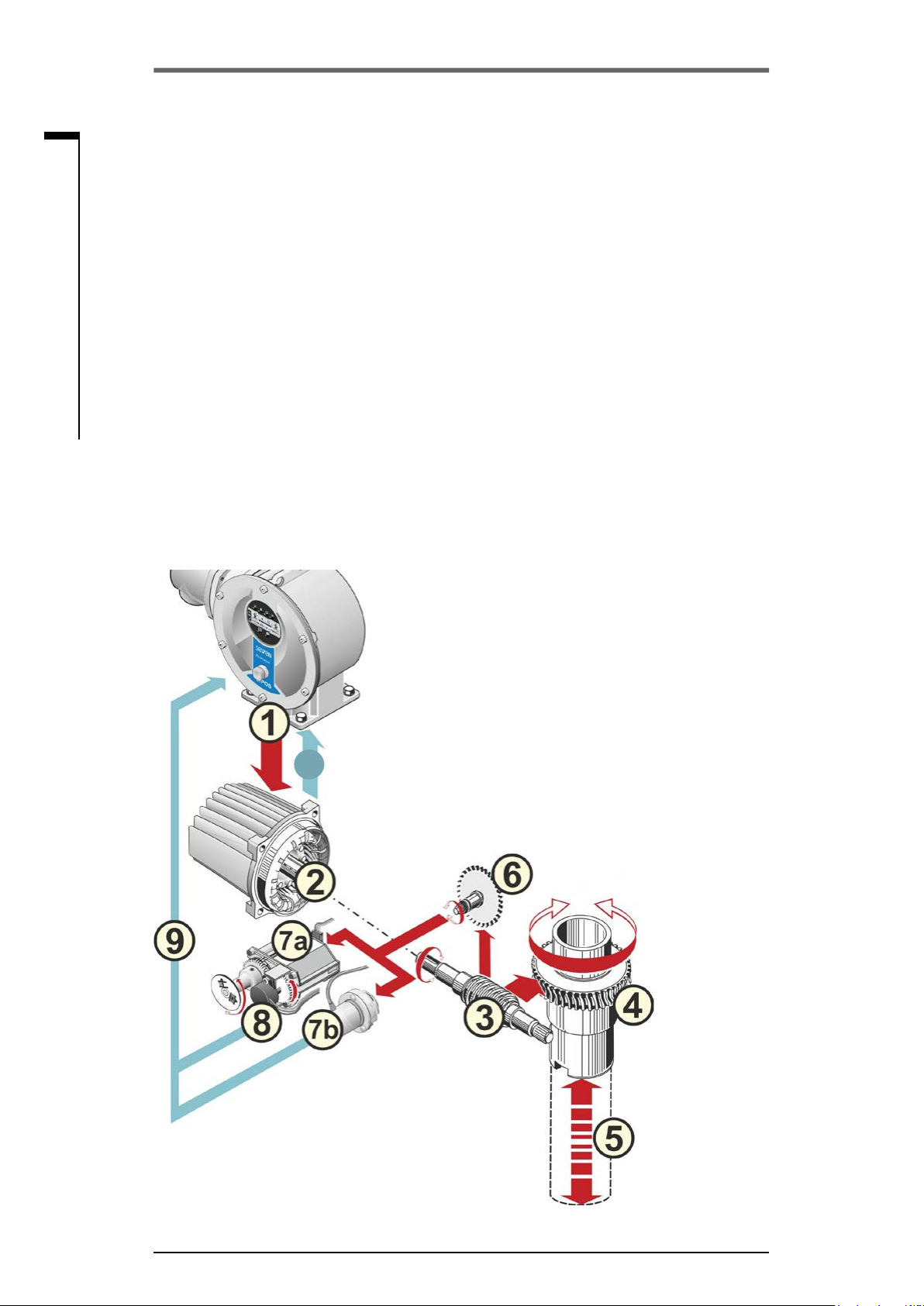
2�1 Functional principle
Description
The electronics with integral frequency converter (1) controls the motor (2). The motor turns the
output drive shaft (4) via the worm shaft (3). The output drive shaft (4) drives a gear or a valve stem
(5) via a stem nut.
The motion of the worm shaft (3) is transferred via the signaling shaft (6) to
■
The signaling gear (7a). The signaling gear reduces the movement and turns the potentiometer
(8)�
or:
■
The non-intrusive position encoder (niP) (7b) for "non intrusive“ version. The non-intrusive position encoder counts the number of rotations and records the position within one rotation. The
position recording is also performed without external power supply.
From the position of the potentiometer or the non-intrusive position encoder, the electronics recognizes the position of the output shaft (9) and therefore the position of the operated valve. The motor
is controlled according to the process requirements.
The torque detection (TD) is performed electronically.
TD
Fig�: Functional principle
Page 6 Y070.301/EN

Operation instructions
SIPOS SEVEN ECOTRON
2�2 Sub-assemblies
The actuators of the SIPOS SEVEN series
comprise two main assemblies: gear unit and
electronics unit.
For details, refer to chapter „Spare parts“.
The main sub-assembly gear consists
of the sub-assemblies:
1 Plug element electronic connection,
2 Motor
3 Gear unit
2 General information
2
4 Signaling gear or non-intrusive position en-
coder (not for 2SG7) with cover
5 Manual drive (with crank or hand wheel),
6 Possible mechanical extensions, depending
on the version
For the small 2SG7 and 2SQ7 part-turn
actuator, the signaling gear is omitted; the gear
unit has a different shape.
The main sub-assembly electronics unit
consists of the sub-assemblies:
1 Electrical connection (two versions available),
2 Plug element gear connection,
3 Electronic housing with cover
4 Power control PCB, including power module
5 Relay board (option)
6 Control PCB with display and eldbus con-
nection (as an option),
General information
Fig�: Gear unit sub-assemblies
Fig�: Electronics unit sub-assemblies
Y070.301/EN Page 7

2
Operation instructions
2 General information
SIPOS SEVEN ECOTRON
General information
2�3 Block diagram (electrical connections)
The block diagram shows the electronic sub-assemblies and the inputs and outputs for possible
customer-specic connections.
Fig�: Block diagram
Page 8 Y070.301/EN

Operation instructions
SIPOS SEVEN ECOTRON
3 Assembly and connection
3�1 Mount to valve/gear
If actuators are delivered mounted to a valve, this step has been done in the valve manufacturer’s
factory. However, the setting has to be checked during commissioning.
■
Heed safety information (refer to chapter 1.1)!
■
Prior to starting the assembly
– Make sure that the intended measures (possible operation of the valve, etc.) are not likely to
cause any injuries to persons or to interfere with the equipment.
– Heed the local ambient conditions, in particular the vibration load, which can be caused
when mounting an actuator to a vibrating valve
■
During assembly, the output shaft insert may fall out of the output drive shaft.
■
When disassembling the electronics cover, make sure the insert does not fall down.
3 Assembly and connection
3
It is recommended that the services and support of the responsible SIPOS Aktorik service centers
are utilized for all planning, installation, commissioning and service tasks.
3�1�1 General assembly instructions for all output shaft types
■
Mounting and operation is possible in any position. Heed the local ambient conditions, in particular the vibration load, which can be caused when mounting an actuator to a vibrating valve.
■
Do not apply force and avoid shocks!
■
Check that the end connection ange and the output shaft type match the valve/gear.
■
Thoroughly clean mounting faces of output mounting anges at actuator and valve/gear.
■
Slightly grease the connection points.
■
Place the actuator on the valve/gear, making sure it is properly centered.
■
Use bolts with at least 8.8 quality. If similar stainless steel bolts are used, they should be greased
slightly using petroleum jelly.
The depth of engagement should be at least 1.25 x the thread diameter.
■
Position the actuator on the valve/gear and tighten the bolts evenly in diagonally opposite sequence.
■
The housing of the actuator consists of an aluminum alloy which is corrosion resistant under
normal environmental conditions. If the paint was damaged during assembly, it can be touched
up with original paint supplied in small quantity units by SIPOS Aktorik.
3�1�2 Output shaft type A
Assembly and connection
Assembly instruction
The stem nut is screwed onto the valve stem by turning the crank handle or the hand wheel.
Spring-loaded A end shafts are subject to high pre-tension. Fitting and removal of the stem nut for
thread cutting must be performed in accordance with assembly instructions!
Fitting and removing the stem nut
If the stem nut was not ordered with a trapezoidal thread (sufx "Y18" to ordering number), or if the
stem nut is worn and has to be replaced, proceed as follows:
Y070.301/EN Page 9
Operation instructions
3 Assembly and connection
SIPOS SEVEN ECOTRON
3
Assembly and connection
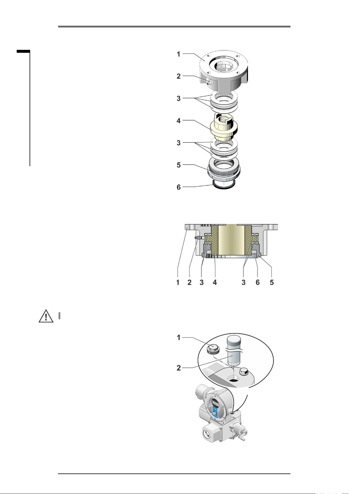
Output ange (g. item 1) does not have to
be removed from the rotary actuator!
1. Unscrew centering ring (g. item 5) from
output ange.
2. Take off stem nut (4) together with axial
needle-roller assembly and axial bearing
washers (3).
3. Remove the axial needle-roller assembly and
the axial bearing washers (3) from the stem
nut.
4. Only if the stem nut was delivered without
thread: Cut a thread in the stem nut (4)
(check the concentricity and the axial run-out
when clamping the stem nut) and clean it.
5. Lubricate axial needle-roller assembly and
axial bearing washers (3) with ball bearing
grease and t them on the new or machined
stem nut (4).
6. Insert stem nut (4) with axial needle-roller
assembly into output ange (claws have to
engage properly into the groove of the output
shaft of the actuator).
7. Screw in the centering ring (5) and tighten it
to the stop. Make sure that the radial shaft
seal (6) is inserted correctly.
8. Using a grease gun, press ball bearing
grease into the nipple until lubricant is discharged between the centering ring (5) and
the stem nut (4).
For output shaft form A, ensure that the valve stem is greased separately!
3�1�3 Mount stem protection tube
1. Remove fastener (g. item 1).
Fig�: Output shaft type A
assembly
Fig�: Output shaft type A
installed
2. Check that the extended stem does not exceed the length of the protective tube.
3. Apply sealing compound to the thread and
the sealing faces (e.g. 732 RTV from Dow
Corning, Munich, Germany).
4. Screw in the stem protection tube (2).
Fig�: Mounting the stem protection
tube
Page 10 Y070.301/EN

Operation instructions
SIPOS SEVEN ECOTRON
3�2 Electrical connection
The components are designed as to ensure that once connected correctly, uninsulated, live parts
cannot be touched directly; i.e. protection against electric shock is provided in accordance with
IP2X or IPXXB.
Dangerous voltages are also applied when the motor is at standstill. Before opening the terminal
cover or the connection hood, disconnect the supply voltage from the actuator.
Allow at least 1 minute for the capacitors to discharge and do not touch any contacts.
■
The supply voltage must always lie within the voltage range specied on the name plate.
■
For short-circuit protection and for disconnecting the actuator from the mains, fuses and
disconnect switches have to be provided by the customer.
■
Mains cable: Use metal cable glands for mains connection.
■
Signal cable: Use metal cable glands with cable shielding for the connection of the signal cable
to avoid the occurrence of electronic faults. The signal cable must be shielded and the shield
must be xed or grounded on both sides. Ensure careful connection of the screen within the
cable gland!
■
It must be ensured that the cable glands and seals (O-rings) are tted carefully and correctly in order to guarantee the enclosure protection. For details of the permissible conductor
cross-sections, see wiring diagram.
■
Cable glands and cables are not included in the scope of delivery.
3 Assembly and connection
3
Assembly and connection
3�2�1 Connection with round plug
1. Unscrew connection hood (g. item 2) with
plug element (1).
2. Unscrew screw plugs from the required cable
entries in the connection hood.
3. Unscrew plug element (1) from connection
hood (2).
4. Screw in the cable gland (3) only slightly and
insert the connecting cables (4).
5. Connect the connecting cables in accordance
with the circuit diagram enclosed in the connection hood, connecting the earth lead to the
provided terminal in the connection box.
6. Screw plug element (1) into the connection
hood (2) and then x connection hood.
7. Tighten cable glands (3).
Fig�: Connection with round plug
Y070.301/EN Page 11
Operation instructions
3 Assembly and connection
SIPOS SEVEN ECOTRON
3
Assembly and connection
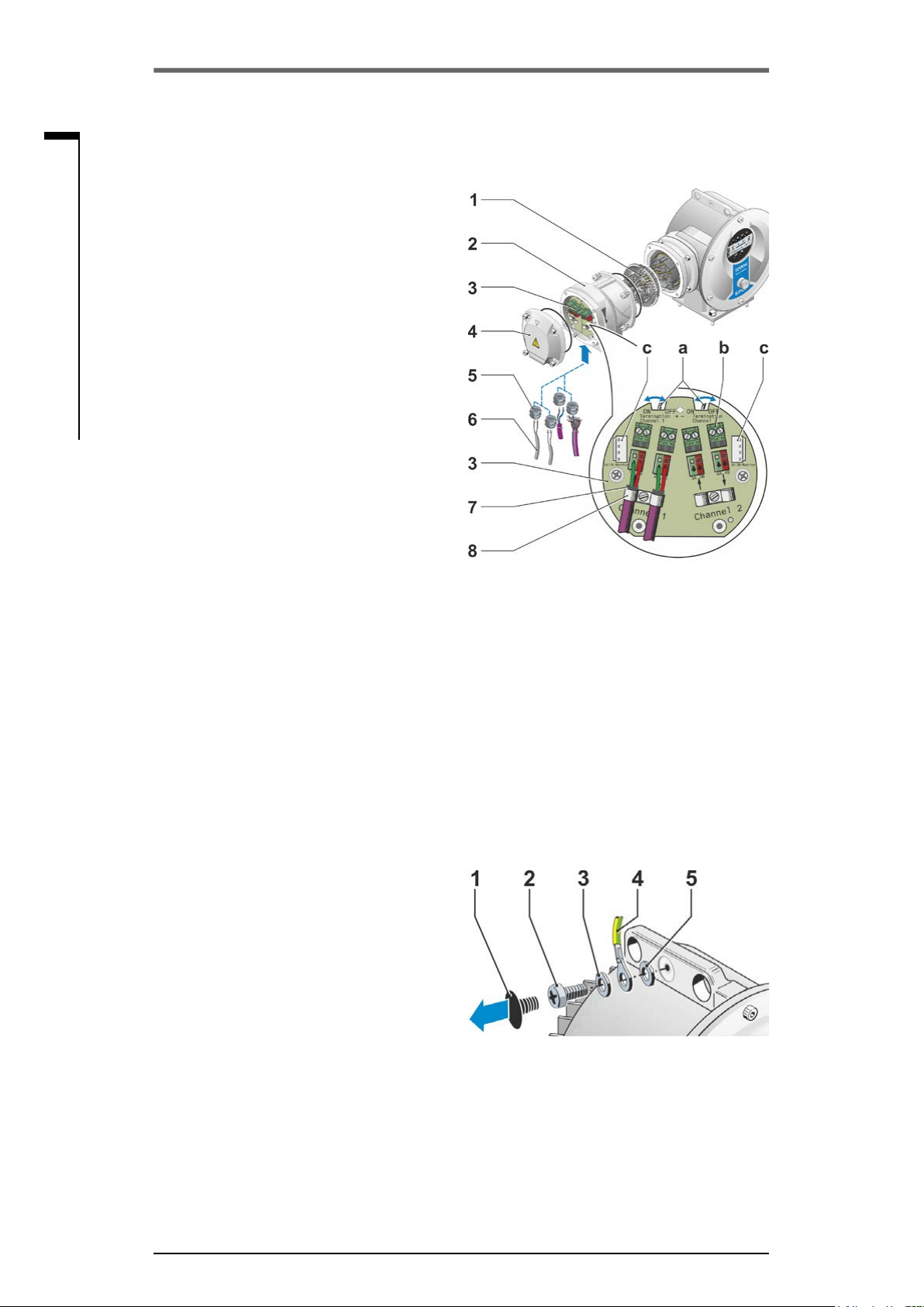
3�2�2 Fieldbus connection
1. Dismantle eldbus connection housing
(g. item 2) and connection cover (4).
2. Unscrew plug element (1) from eldbus con-
nection housing (2).
3. Unscrew screw plugs from the required cable
glands in the eldbus connection housing.
4. Screw in the cable glands (5) only slightly and
insert the connecting cables (6).
For eldbus cables, cable glands without
shield are sufcient, refer to point 7 below.
5. Connect the mains cables and, if required,
signal cables in accordance with the circuit
diagram enclosed in the connection housing,
connecting the earth lead conductor to the
provided terminal in the connection box.
6. Fit plug element (1) into eldbus connection
housing (2) again.
7. Connect eldbus connecting cables to the
bus termination PCB (3). Lead shielding (7)
under metal clamp (8).
8. Fit connection cover (4) and eldbus connec-
tion housing (2) again.
9. Tighten cable glands (5).
Fig�: Fieldbus connection
a = If the actuator is the last device of the bus
b = Connection for external 24 V power supply.
c = Connection for PROFIBUS DP bus monitor
3�2�3 External potential conductor connection
The external potential conductor connection
can be used for functional grounding and not for
protective grounding.
1. Remove plastic fastener (1) from the electronics housing.
2. Fit potential conductor (4) and gripping disc
(5) (shims point in direction of the housing!)
with M5 screw (2) and washer (3).
Fig�: Fit potential conductor
segment, the termination resistor must be
set to ON or a termination must be done
externally.
Enables communication even if the mains
are disconnected.
(Protocol Analyzer).
Page 12 Y070.301/EN
Operation instructions
SIPOS SEVEN ECOTRON
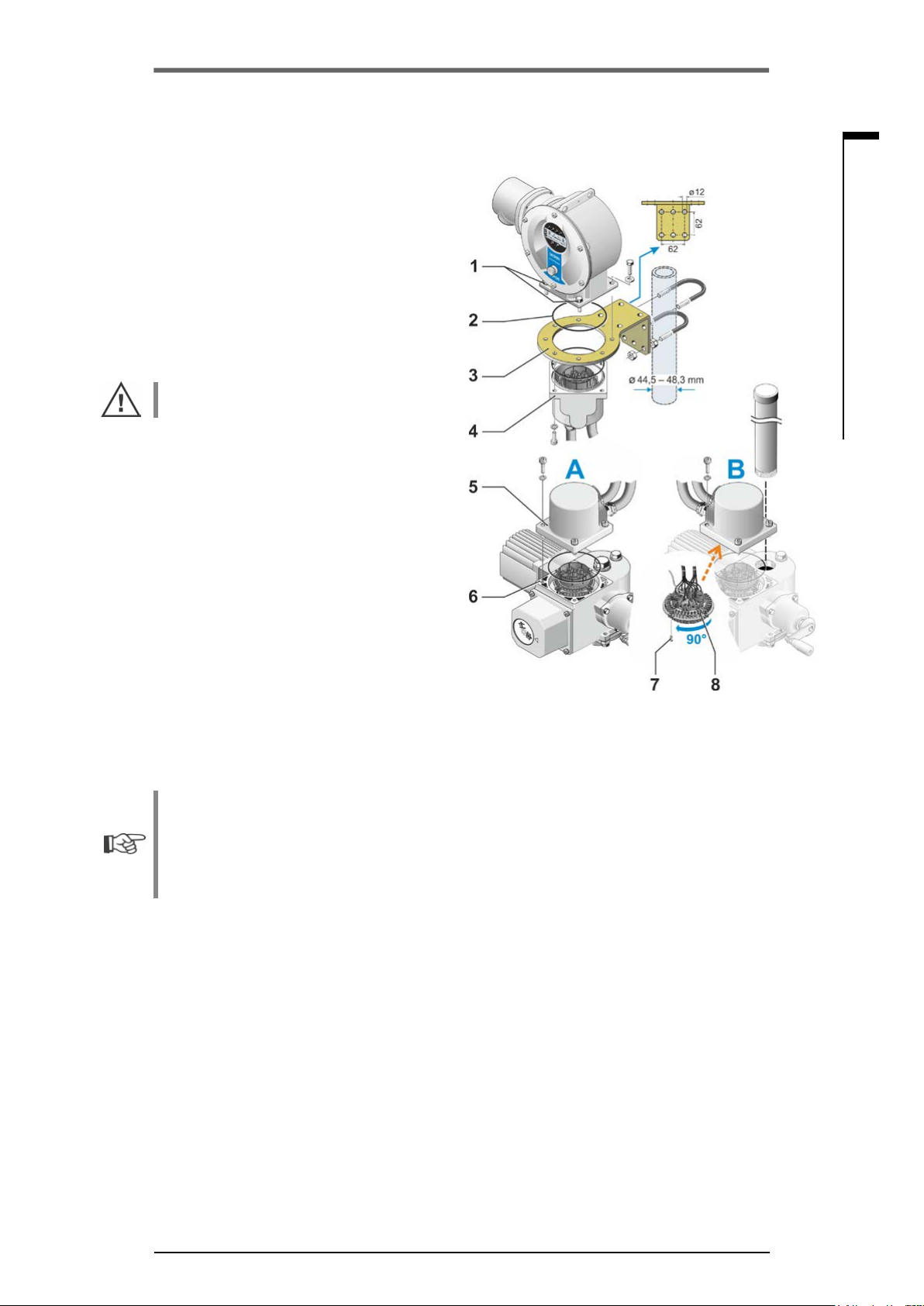
3�3 Separate mounting
If the ambient conditions such as extreme
vibration, high temperature and/or if access is
difcult, the electronics unit is to be mounted
separately from the gear unit.
The assembly kit for mounting the gear unit
and electronics unit separately can be ordered
directly with the actuator or separately as an
accessory (2SX7300-. . .). The assembly kit is
pre-assembled. If the assembly kit is ordered
directly with the actuator, it is included separately with the actuator.
Before starting the work, disconnect actuator
from the mains!
Procedure
1. Install mounting bracket (g. item 3) at the
mounting location of the electronics unit.
2. Remove electronics housing (1) from the gear
unit (6) and mount it on the mounting bracket
(3) with the O-ring (2).
3. Standard assembly, refer to A
Fit "Separate mounting“ assembly kit: Plug
cover with contact pins (4) on lower side of
wall bracket (3) and plug cover with contact
sockets (5) on the gear unit (6).
4. Assembly with stem protection tube, refer
to B
Turn connection hood by 90° or 180° to ensure that cables are not impaired by the stem
protection tube:
Remove screws (7) from round plug, turn
round plug by 90° to 180° and x screws
again. Continue as described in section 3.
3 Assembly and connection
3
Assembly and connection
Fig�: Separate mounting
A = Standard,
B = with stem protection tube
■
During installation, it is important to ensure that the O-rings are tted correctly in order to
guarantee the degree of protection.
■
Generally, it has to be ensured that movable parts, e.g those of the swing lever of the part-turn
actuator, are not impaired by the cables.
■
In exceptional cases, the motor might become very hot. Therefore the cables should not touch
the motor.
Specication of the connecting cable between the electronics unit and the gear unit
Mains connection: shielded and UV resistant, e.g. TOPFLEX®-611-C-PUR-4G1,5/11,3 cable.
TOPFLEX® is a trademark of HELUKABEL.
Control connection: Shielded and UV resistant, e.g. L IY11Y-7x2x0,5/11,4-S.
The connecting cables are available in different lengths:
■
Standard lengths: 3 m; 5 m; 10 m,
■
With additional equipment (lter) up to 150 m.
For separate mounting exceeding 10 m including lter, the value "Cable length exceeding 10 m
and connection via LC lter“ has to be activated for the "Separate mounting" parameter. Refer to
COM-SIPOS tab “Other"
Y070.301/EN Page 13

4
Operation instructions
4 Instructions on operator control and operation
SIPOS SEVEN ECOTRON
Instructions on operator control and operation
4 Instructions on operator control and operation
The COM-SIPOS PC programming software provides for comfortable programming and reading
of the actuator data, refer to „4.8 COM-SIPOS PC programming software“ on page 24.
4�1 Crank handle, hand wheel
■
Motor driven operation of the crank handle/hand wheel is not permitted.
■
After commissioning, the actuator must not be operated beyond the parameterized end positions using the crank handle/hand wheel.
■
When pressing in the crank handle/the hand wheel, make sure that the hand is removed between crank handle/ hand wheel and housing: Danger of crushing! See the following operation
step 3.
The crank handle/handwheel does not rotate during motor operation
Operation
Operation of all actuators except for 2SG7
and 2SQ7:
1. The actuator must be at standstill (1).
2. Remove the clamp (option) (2). The clamp
is used as protection against accidental
engaging of the crank handle/hand wheel, if
the actuator is exposed to heavy vibration or
water pressure (enclosure protection IP68-8).
3. Press crank handle/hand wheel in direction of
the gear housing against spring force (3) and
turn (4). (Caution: Danger of crushing when
engaging!)
If crank handle/hand wheel is pressed in, the motor stops. The actuator can only be operated electrically once the crank handle/hand wheel is released.
Fig�: Operate crank handle
If the actuator is operated manually in "REMOTE“ state and an operation command is present, the
actuator is immediately operated after releasing the crank handle/hand wheel.
For 2SG7 only:
Turn hand wheel without pressing it in. Manual operation interferes with motor operation: If the hand
wheel is turned during motor operation, the positioning time is either extended or reduced, depending on the direction of rotation.
For 2SQ7 only:
Only engage manual drive while motor is at
standstill. Manual operation is automatically
disengaged when switching on the motor.
Direction of rotation
Clockwise turning of crank handle/hand wheel
leads to
■
2SA7 rotary actuator: Clockwise rotation of the output drive shaft (exception: 2SA7.7. and
2SA7.8.)
■
2SG7, 2SQ7 part-turn actuator: With view on the mechanical position indicator: clockwise rotation
at the coupling or at the swing lever.
Depending on the potentially installed gear unit, the direction of rotation may vary.
Fig�: Engage manual operation for 2SQ7
Page 14 Y070.301/EN

Operation instructions
SIPOS SEVEN ECOTRON
4 Instructions on operator control and operation
4�2 Light emitting diodes (status and fault signals)
The actuator informs the user via
■
Light emitting diodes (LEDs)
■
Display (refer to chapter „4.3 Display“ on page 19).
This chapter contains an overview of light emitting diodes and the information they provide for the
user.
4�2�1 Overview of light emitting diodes
The LEDs indicate the state of the actuator:
4
1. Light emitting diode
The CLOSE LED is ashing if the actuator
moves in CLOSE direction and is continuously illuminated if the actuator is in end
position CLOSED.
2. Light emitting diode
The LOCAL LED is illuminated if "local operation” is selected.
3. Light emitting diode
The LOCAL LED is illuminated if "REMOTE
mode” is selected.
4. Light emitting diode
The OPEN LED is ashing if the actuator
moves in CLOSE direction and is continuously illuminated if the actuator is in end
position OPEN.
5. LED
operation, refer to “Status and fault signals“
overview below. During end position adjustment, it will be illuminated until the end
position adjustment is OK.
6. LED
is ready for operation. During end position
adjustment and when the crank handle/hand
wheel is operated as well as during faults of
the change over from REMOTE to LOCAL,
the green LED will be ashing. Refer also to
“Status and fault signals“ overview below.
(red) indicates a fault signal during
(green) is illuminated if the actuator
(CLOSE, yellow).
(LOCAL, yellow).
(REMOTE, blue).
(OPEN, green).
Instructions on operator control and operation
Fig�: LEDs
Y070.301/EN Page 15

Operation instructions
4 Instructions on operator control and operation
SIPOS SEVEN ECOTRON
4
Instructions on operator control and operation
4�2�2 Indication of control, operation direction, end position
When illuminated or by ashing, the light emitting diodes (LEDs) indicate
■
the control type: LOCAL mode or REMOTE mode,
■
the direction (OPEN or CLOSE) during operation,
■
the end position if the actuator is in one of the end positions (OPEN or CLOSED).
The states of the LEDs (off – illuminated – ashing) are represented in the operation instructions as
follows:
LED is not illuminated (off)
LED is illuminated
LED is ashing
Arrangement of the LEDs State of the LEDs Explanation
(yellow) (green)
(yellow)
(green)
(blue)
(red)
Both LEDs are not illuminated:
Actuator is at standstill and in mid-travel.
The CLOSE LED is ashing:
The actuator operates in CLOSE direction.
The OPEN LED is ashing:
The actuator operates in OPEN direction.
The CLOSE LED is illuminated:
The actuator is in end position CLOSED.
The OPEN LED is illuminated:
The actuator is in end position OPEN.
The actuator is in “LOCAL mode”.
The actuator is in “REMOTE mode”.
The LEDs indicate: "Ready" or "Fault" and
the states during commissioning. Refer to
"Status and fault signals" chapter below.
Page 16 Y070.301/EN
Operation instructions
SIPOS SEVEN ECOTRON
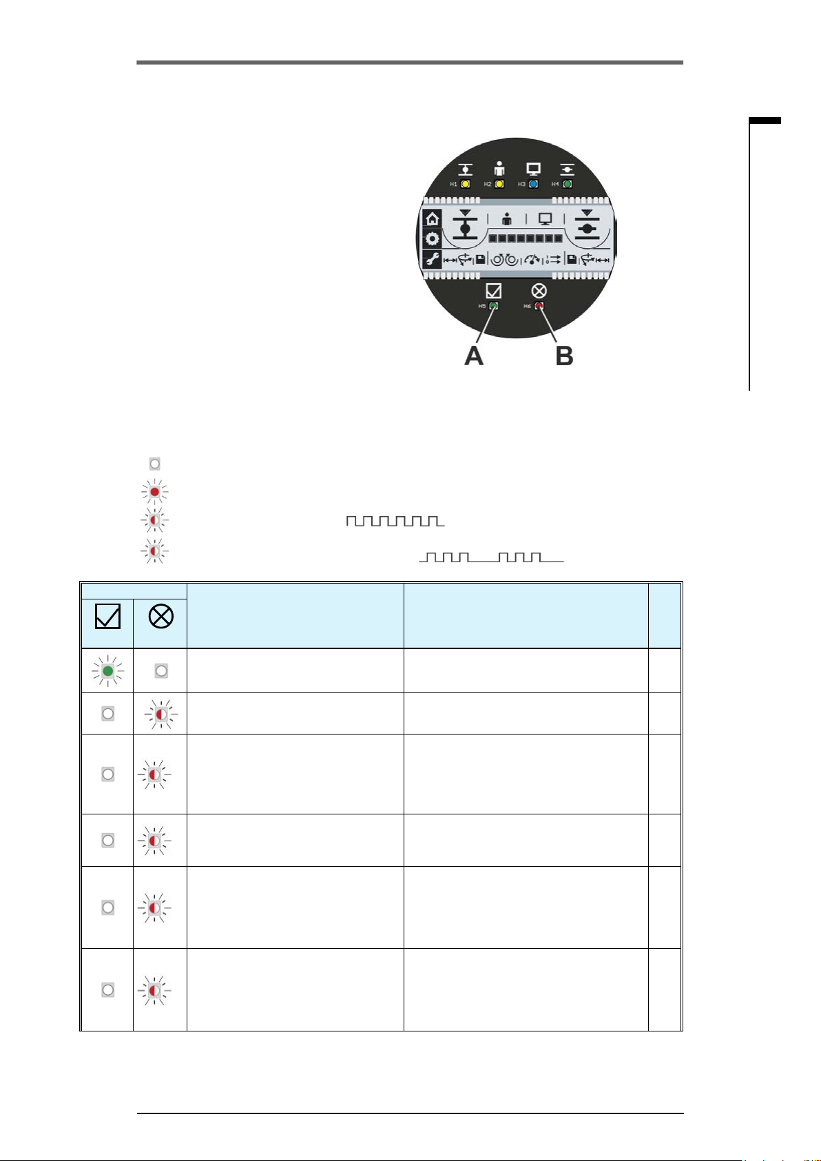
4�2�3 Status and fault signals
LEDs ”Ready“ (g. item A) and the ”Fault“
(Pos. B) indicate the device state and the
signals during faults. This enables an analysis
of the faults. Some of the "Fault signals” can be
reset, refer to right column "Fault type" in the
following table.
The symbols have the following meaning:
■
S – automatically resetting fault signals
Once the cause of the fault is eliminated, the
fault signal is automatically reset.
■
N – Non-resettable fault signals.
The cause of the fault must be eliminated.
The table below lists possible states of the
“Ready” and “Fault” LEDs and the respective
signications as well as corrective actions. The
states of the LEDs (off – illuminated – ashing)
are represented in the operation instructions as
follows:
4 Instructions on operator control and operation
4
Fig�: A = LED ”Ready“ and
B = LED ”Fault“
(green)
LED
= LED is not illuminated (off)
= LED is illuminated
= LED is continuously ashing
= LED is ashing periodically. The ashing, here 3 times, is repeated after a pause
3 x
of 1 s: 3 x ashing + pause = 1 period
Signication Corrective actions
(red)
The actuator is ready for operation.
Fault: commissioning is invalid
Fault:
2x
Motor temperature too high
Fault:
3x
Mains failure or excessive mains
voltage uctuations.
Fault: Open-circuit behavior of
■
Travel potentiometer/non-intrusive
4x
position encoder or temperature
sensor;
■
feed cables from REMOTE.
Fault:
Travel is blocked, i.e. tripping torque
5x
reached within travel.
Actuator can still be operated into the
opposite direction (leaving the block)
Fault
type
Perform commissioning.
Refer to „5 Commissioning“ on page 25.
■
Check valve for sluggishness.
■
Reduce number of starts.
■
Ambient temperature impermissibly high
■
Check "Separate mounting“ parameter
using COM-SIPOS.
Check supply voltages. S
■
Check cables for separate installation.
■
Check cables (eldbus, if applicable)
■
Check valve for sluggishness.
■
Increase torque values.
■
Check "Separate mounting“ parameter
using COM-SIPOS.
Instructions on operator control and operation
N
S
S
S
Y070.301/EN Page 17

4
Operation instructions
4 Instructions on operator control and operation
SIPOS SEVEN ECOTRON
Instructions on operator control and operation
(green)
LED
(red)
6x
1x
1x
1x 2x
2x
2x
3x
4x
Fault:
■
End positions were passed
■
Fault during runtime monitoring
Fault: Device failure. Service, repair necessary.
Actuator does neither respond
to remote control nor to Drive
Controller.
Commissioning (IBS) active:
End position adjustment OK
Commissioning active:
End position adjustment not OK
Commissioning active:
Commissioning not possible.
Crank handle/hand wheel operated.
Commissioning active:
Crank handle/hand wheel operated
during commissioning.
Commissioning active:
Commissioning via USB or eldbus
active, i.e. on-site commissioning
and operation via local control unit
not possible.,
Change-over from REMOTE to
LOCAL blocked.
Signication Corrective actions
■
Recommissioning.
■
Check signaling gear and travel potentiometer.
■
Check valve for sluggishness.
■
Increase torque values.
■
Check "Separate mounting“ parameter
using COM-SIPOS.
Slide BOOT switch (1) on control PCB
and press RESET (2).
--- ---
Perform commissioning. N
Abort commissioning and evaluate ash
pattern.
■
Release crank handle/hand wheel.
■
Check cables for separate installation.
Release crank handle/hand wheel. S
--- ---
Enable via eldbus. S
Fault
type
N
N
S
Page 18 Y070.301/EN

Operation instructions
SIPOS SEVEN ECOTRON
4�3 Display
The graphic segment display utilizes different symbols to indicate the actuator state during
operation, commissioning and parameterization. Clear representation and unambiguous symbols
enable simple operation. The Drive Controller (rotary push button) enables operation directly at the
actuator.
This chapter provides an overview of symbols in the display and the information they provide for the
user. Once acquainted with the signication of the symbols, actuator operation is quick and easy.
4 Instructions on operator control and operation
4
Fig�: Segment display
Item Description on page ▼
1
2
3
4
5
6
7
8
9
10
11
12
13
Parameterization menu 28
End position adjustment menu 37
Local operation menu 22
Indicates the cut-off mode in CLOSE
direction:
Travel dependent or
Torque dependent 38
Indicates that end position
CLOSED is selected
Tick conrms correct end position adjustment
Symbol for end position
CLOSED
LOCAL mode 22
REMOTE mode 22
Symbol for end position OPEN 37
Indicates that end position
OPEN is selected
Tick conrms correct end position adjustment
Indicates the cut-off mode in OPEN
direction:
Torque dependent or
38
37
37
37
37
37
37
Item Description on page ▼
Setting of the cut-off mode in end posi-
14
tion OPEN:
Travel dependent cut-off mode
or
Torque dependent cut-off mode 37
15
16
17
18
19
20
21
Save settings for end position
OPEN
Output signal set for binary
outputs and control mode
Speed 30
Scale shows
■
depending on the preselected
function; the setting for
– tripping torque
– output speed
– output signal set
– control mode
■
the position during travel
Closing direction adjustment:
clockwise or 37
counterclockwise 37
Save settings for end position
CLOSED
Setting of the cut-off mode in end
position CLOSED:
Torque dependent cut-off mode 28
37
37
37
31
28
30
31
32
21
37
Instructions on operator control and operation
Travel dependent 37
Y070.301/EN Page 19
Travel dependent cut-off mode 37
4
1
2
5
3
4
Operation instructions
4 Instructions on operator control and operation
SIPOS SEVEN ECOTRON
Instructions on operator control and operation
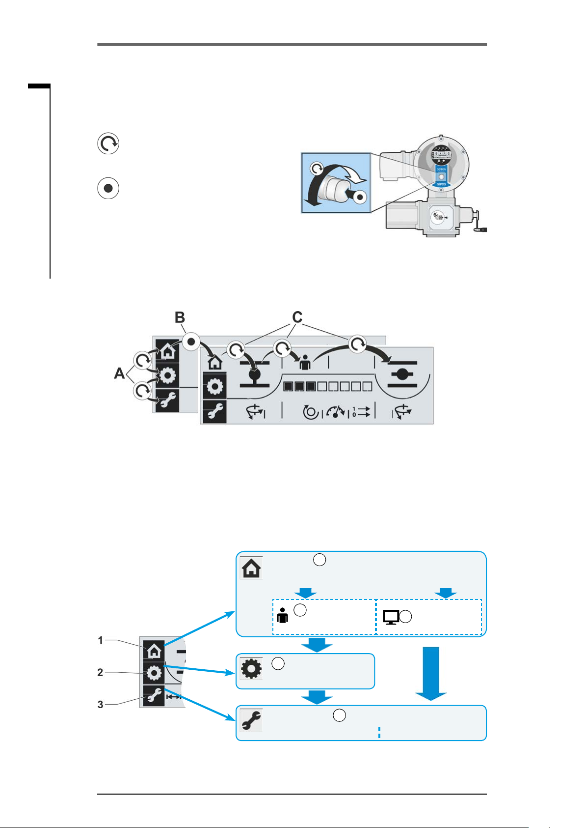
4�4 Navigation in the display
4�4�1 Operation of the ”Drive Controller“ rotary push button�
= Turn Drive Controller:
Select menu item,
end position, setting
= Press Drive Controller:
Conrm selection.
If the Drive Controller is not operated for
more than 10 minutes, the display illumination
changes to standby mode. Hold down Drive
Controller for 2 s or turn by 3 latching positions
to reactivate display.
Fig�: Operate the Drive Controller
4�4�2 Navigation through the menus
Fig�: Navigation in the display
A = Turn Drive Controller:
Selection between menus.
Selected menu is ashing.
4�5 Menu structure
The display proves three menus:
1 Local operation
2 End positions
3 Parameter
Fig�: Menus
B = Press Drive Controller:
Conrm selected menu. Actuator
changes to selected menu and
the menu symbol is no longer
presented inversely.
Localoperation menu
Change over between
LOCAL mode and Remote mode
LOCAL mode
Operate actuator
End position menu
End position adjustment
Change parameter View parameters
Page 22
Page 22
Page 35, 37
Page 28
C = Turn Drive Controller:
Change between menu
items within a menu.
Page 22
REMOTE mode
Parameters menu:
Page 21
Page 41
Page 22
Page 42
The overview shows the menu structure. The encircled digits refer to the explanation below, the
page numbers to the detailed description.
Page 20 Y070.301/EN
Operation instructions
SIPOS SEVEN ECOTRON
Explanation
Use the ’Local operation‘ menu to change over between ’LOCAL mode‘ and ’REMOTE mode‘.
The actuator can be operated manually in local operation.
The ’End position‘ menu is used to set the closing direction, end positions OPEN and
CLOSED and the respective cut-off mode.
If the ‘Parameter’ menu is selected in ‘LOCAL mode’, the parameter values can be modied.
If the ‘Parameter’ menu is selected in ‘REMOTE mode’, the set parameter values may be
viewed but cannot be modied.
4�6 Menu overview
4 Instructions on operator control and operation
4
The following descriptions show the display indications and functions available for the individual
menus.
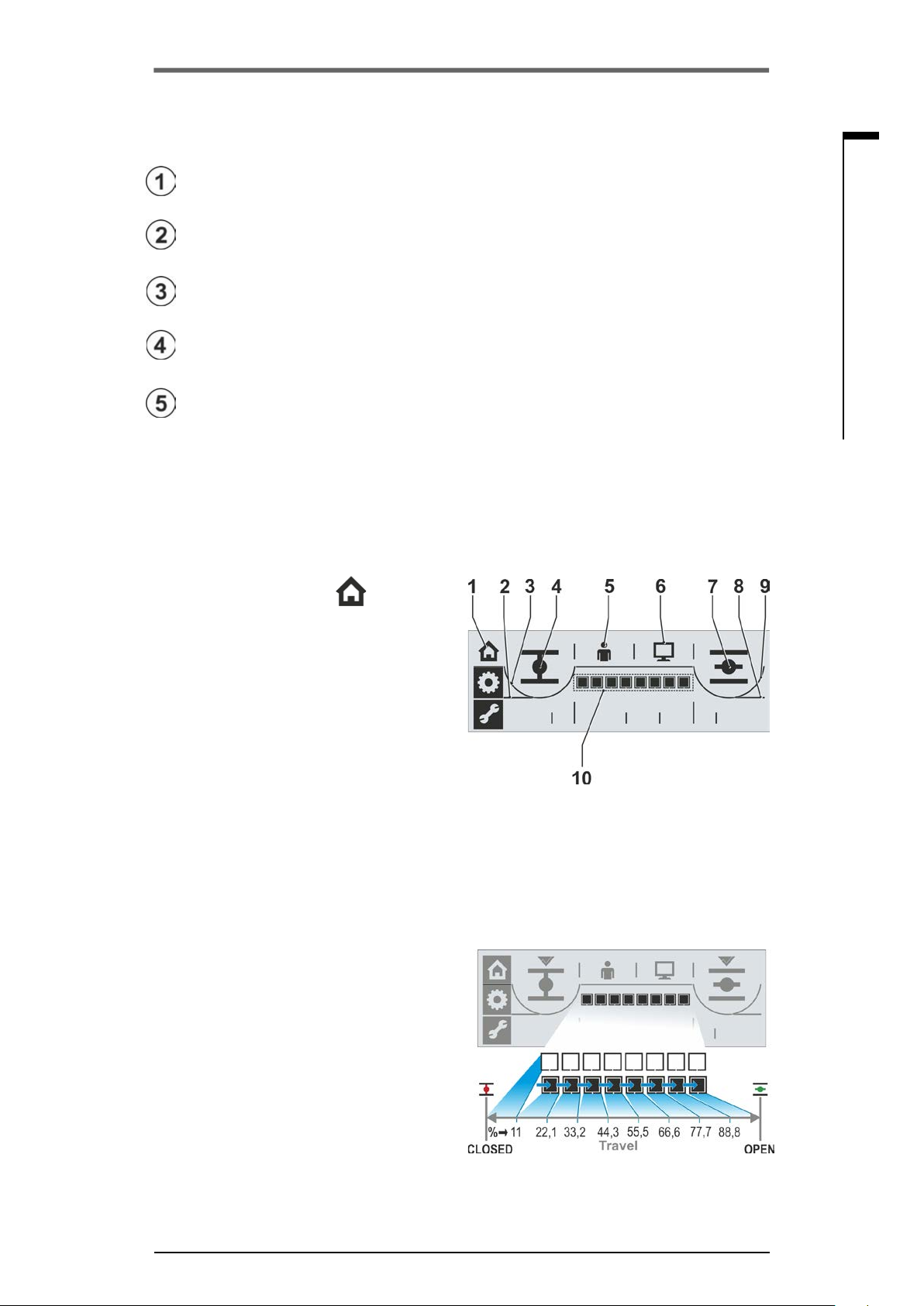
4�6�1 Local operation menu
1 ‘Local operation’ menu is active.
2 Cut-off mode in end position CLOSED is
travel dependent (straight line),
or
3 Cut-off mode in end position CLOSED is
torque dependent (bent line),
4 CLOSE symbol for selection of CLOSE direc-
tion into which the actuator is operated.
5 Control performed locally (LOCAL mode),
or
6 Control performed by DCS/control room (RE-
MOTE mode).
7 OPEN symbol for selection of OPEN direction
into which the actuator is operated.
8 Cut-off mode in end position OPEN is travel
dependent (straight line),
or
9 Cut-off mode in end position OPEN is torque
dependent (bent line),
10 Position indicator; the black rectangles
(segments) indicate how far the actuator has
moved in position OPEN. Each segment corresponds to approx. 11 % of the entire travel.
Refer to gure 2 on the right
Example:
■■■■□□□□ = position OPEN 44.3 – 55.5 %.
If there is no segment active, the actuator is
between CLOSED and 11 % OPEN.
Instructions on operator control and operation
Fig� 1: Local operation menu overview
Fig� 2: Position indicator
Y070.301/EN Page 21

Operation instructions
4 Instructions on operator control and operation
SIPOS SEVEN ECOTRON
4
Instructions on operator control and operation
4�6�2 End position menu
1 ‘End position‘ menu is active.
2 Indicates that end position CLOSED is
selected.
3 Cut-off mode in end position CLOSED:
a = travel dependent;
b = torque dependent
4 Save position for end position CLOSED.
5 Tick indicates that end position CLOSED
has been correctly saved.
6 Closing direction
a = counterclockwise;
b = clockwise.
7 Tick indicates that end position OPEN has
been correctly saved.
8 Save position for end position OPEN.
9 Cut-off mode in end position OPEN:
a = torque dependent;
b = travel dependent
10 Indicates that end position OPEN is
selected.
Fig�: End position menu overview
4�6�3 Parameter menu
1 ‘Parameter‘ menu is active.
2 Tripping torque in CLOSE direction,
3 Scale; indicates the setting of the respective
parameters.
4 Speed.
5 Output signal set selection for signaling
outputs and control modes.
6 Tripping torque in OPEN direction.
If the ‘Parameter’ menu is accessed in
´’REMOTE’ mode, the parameter values may
only be viewed.
4�7 ‘Local' actuator operation
The actuator can only be operated for valid end position setting! For local actuator operation,
‘LOCAL mode’ must be active and the ‘Local operation’ menu selected. The menu can be accessed
from “REMOTE mode” or one of the two other menus.
Change from ’REMOTE mode‘ to
’LOCAL mode‘ and operate the actuator�
The actuator is in the "REMOTE mode" state.
REMOTE LED is illuminated and the symbol for
REMOTE mode
is indicated (g. 1).
Fig�: Parameter menu overview
Fig� 1: Display indicates REMOTE
mode active
Page 22 Y070.301/EN

Operation instructions
SIPOS SEVEN ECOTRON
1. Select LOCAL mode: Turn Drive Controller
counterclockwise.
’LOCAL mode‘ symbol
ashing (g. 2).
appears and is
4 Instructions on operator control and operation
4
2. Conrm selection: Press Drive Controller.
LOCAL mode is active, the symbol for
LOCAL mode is continuously displayed
and the yellow Local LED is illuminated.
The symbol for REMOTE mode and the
REMOTE LED are not illuminated (g. 3).
3. Select operation direction:
– CLOSE > Turn Drive Controller coun-
terclockwise, until CLOSED symbol is
displayed.
– OPEN > Turn Drive Controller clockwise
until OPEN symbol is displayed.
4. Operate actuator: Press Drive Controller.
The actuator is operated in direction of
the selected end position
indicator is changing accordingly, see also
previous chapter 4.6.1.
If you hold down the Drive Controller for more than 3 sec., self-retaining starts.
Pressing the Drive Controller once again will stop the actuator.
1
and the position
Fig� 2: Change over to local operation
mode is selected
Fig� 3: Local operation mode is active
Changing from one of the menus to the
’Local operation‘ menu�
1. Complete end position adjustment or
parameterization and select ‘Local operation‘
(house symbol).
The house symbol is ashing inversely
(g. 4).
2. Conrm selection. Press Drive Controller.
The symbol is ashing normally (g. 5) and
the local operation menu is active.
3. Continue as described above from step 4.
Instructions on operator control and operation
Fig� 4: Local operation menu selected
Fig� 5: Local operation menu active
1
If the actuator has switched off automatically before reaching the end position, two causes are possible:
■
Sluggish nal closing element or unfavorable torque curve. In this case, cancel procedure or
■
Valve has reached mechanical stop, in this case readjust end positions (chapter 5)
Y070.301/EN Page 23
4
Operation instructions
4 Instructions on operator control and operation
SIPOS SEVEN ECOTRON
Instructions on operator control and operation
4�8 COM-SIPOS PC programming software
The COM-SIPOS PC parameterization program is a software tool for
■
Observe: Reading the actuator parameters and the device state;
■
Diagnosis: Trouble shooting;
■
Loading new rmware: Software update to the state-of-the-art;
■
Archiving: Saving of the actuator parameters on a PC/laptop;
■
Operation: Operation of the actuator in LOCAL mode;
■
Parameterization: Settings which can be changed in LOCAL mode in the display can
also be changed using COM-SIPOS. Furthermore, the following control types can be
set for REMOTE mode:
– Binary: Pulse contact
– Fieldbus: Permanent contact
– Binary: Permanent contact
■
For further settings via
COM-SIPOS, refer to chapter
„5.4 Further settings via
COM-SIPOS“ on page 32.
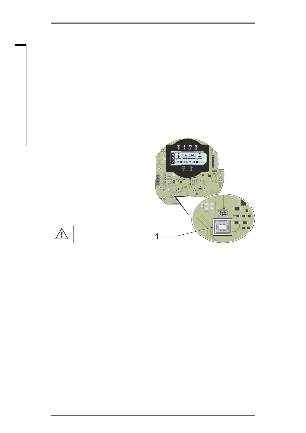
The connection between computer
and actuator is established via a USB
cable A/B. The USB port is located on
the control PCB, refer to g. item 1.
COM-SIPOS is available incl. USB
cable and user manual (on ash
drive); order number:
2SX7100-3PC02.
When disassembling the electronics
cover, make sure the insert does
not fall down.
Fig�: USB connnection on control PCB
Page 24 Y070.301/EN

Operation instructions
SIPOS SEVEN ECOTRON
5 Commissioning
5�1 General information
5�1�1 Observe the following notes
■
Before performing any work on the installed actuator, check with the plant personnel in charge
that the commissioning may not cause any fault of the plant or hazards to persons.
■
If a cut-off mode is selected that is not appropriate for the valve, the valve may be damaged!
■
There are hazardous voltage levels within the actuator.
■
When changing to 'REMOTE' mode, the actuator moves once an operation command from the
DCS is present!
It is recommended that the services and support of the responsible SIPOS Aktorik service centers
are utilized for all planning, installation, commissioning and service tasks.
5�1�2 Ensuring prerequisites for commissioning
5 Commissioning
5
Commissioning
Check and ensure the following points after assembly or during revision and inspection:
■
The actuator is correctly assembled.
■
All xing screws and connecting elements are rmly tightened.
■
The grounding and equipotential bonding has been correctly implemented.
■
The electrical connections have been correctly implemented.
■
All protection against accidental contact has been implemented for moving or live parts.
■
Neither the actuator nor the valve is damaged.
■
The permitted temperature range for the actuator is maintained and heat dissipation from the nal
control element is also taken into account.
Further checks are also necessary in accordance with the plant-specic conditions.
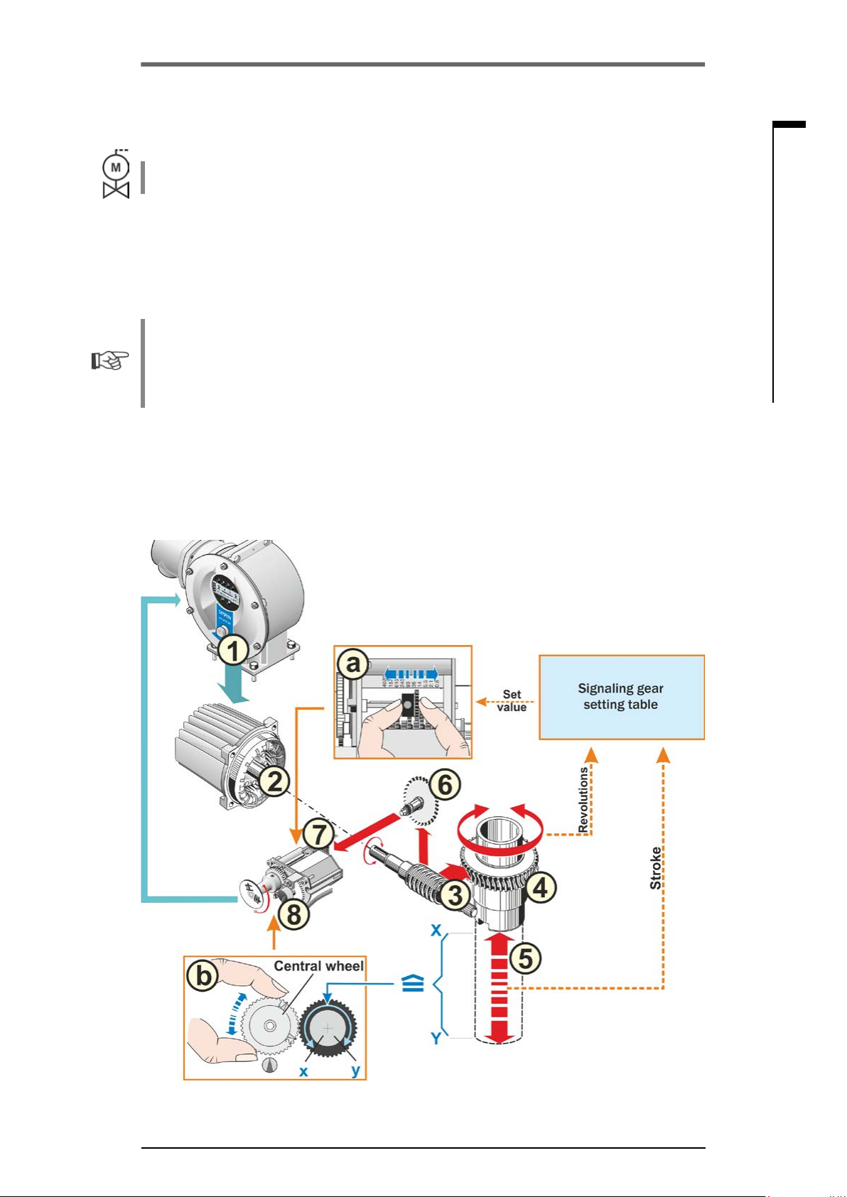
5�2 Procedure for commissioning
Commissioning is divided into 4 main steps:
1. Change actuator to LOCAL mode
2. Check/set parameters
3. For version with signaling gear: Check/adjust signaling gear ratio.
4. Adjust end positions including closing direction and cut-off mode
Y070.301/EN Page 25

Operation instructions
5 Commissioning
SIPOS SEVEN ECOTRON
5
Commissioning
The following overview shows the individual steps of commissioning�
The numbering of the pages indicate the detailed description.
local operation.
tripping torque
Action Explanation
Switch actuator to LOCAL mode
Change to ‘Local operation’ menu
and
select
Check/set valve parameters
Program
Select local operation Page 22
Change to ‘Parameter’ menu Page 28
■
Program in end position
CLOSED and end position
OPEN.
■
For 2SQ7, set at torque switch
mechanism
For a
description,
refer to:
Page 28
Supp. instr.
Page 5
Program speed or
positioning time
Select output signal set
and control mode
For version with signaling gear: Adjust signaling gear ratio
Adjust
signaling gear
Check/program speed or
positioning time.
■
Select one of the 4 output signal
sets and determine the assignment at the 5 signal outputs.
(Determine predened signals).
■
Select control mode:
–
binary: pulse contact
–
binary: permanent contact
–
eldbus: permanent contact
Check/adjust signaling gear ratio. Page 36
Adjust end positions including closing direction and cut-off mode
Change to ‘End position’ menu Page 37
Select closing
direction
Select rst
end position
/
/
Check/adjust closing direction:
counterclockwise or clockwise
Cannot be selected for 2SQ7.
Select symbol for end position
OPEN or CLOSED. (In our
example end position OPEN. It is
not relevant which end position is
set rst.)
Page 30
Page 31
Page 32
Page 38
Page 38
Cut-off mode 1. Program
Page 26 Y070.301/EN
end position
/
Check/program cut-off mode in the
rst end position; travel-dependent
or torque dependent.
Page 38

Operation instructions
SIPOS SEVEN ECOTRON
Action Explanation
Turn
central wheel
to mid position
5 Commissioning
5
For a
description,
refer to:
Signaling gear only:
1
1
2
2
2
1
Turn central wheel so that arrows 1
and 2 point in upward direction.
Page 38
Approach position
of rst end position
Adjust
central wheel
Save position
of rst end position
Adjust position
indicator
Cut-off mode 2. Program
end position
Approach position of
second end position.
Approach position of rst end
position (here end position OPEN).
Commissioning
1
2
2
2
1
1
Signaling gear only:
Turn central wheel until arrow
points downward and the save
symbol appears in the display.
Turn Drive Controller until Save
symbol starts to ash. Press Drive
Controller.
If mechanical position indicator is
available, check/adjust position
OPEN.
Check/program cut-off mode in the
second end position; travel-
/
dependent or torque dependent.
Move actuator to second end
position (Here end position
CLOSED).
Page 39
Page 40
Page 39
of second end position
Save position
Select Save symbol and
acknowledge.
If mechanical position indicator is
Page 40
available, check/adjust position
Adjust position
CLOSED.
indicator
Change over to
REMOTE control
Change to REMOTE mode in the
‘Local operation’ menu.
Page 22
You do no have to perform all settings. Depending on whether settings have already been
specied when ordering the actuator or whether the actuator was delivered mounted to the valve,
checking the settings will be sufcient.
Y070.301/EN Page 27
5
Operation instructions
5 Commissioning
SIPOS SEVEN ECOTRON
Commissioning
5�3 Check/set parameters
Parameters ‘Cut-off torque CLOSE‘, ’Cut-off torque OPEN‘ ’Speed‘, and ’Signal set‘ are set/programmed via the ’Parameter‘ menu. The sequence of the programming steps is not binding. In the
following descriptions, the sequence complies with the indication in the display.
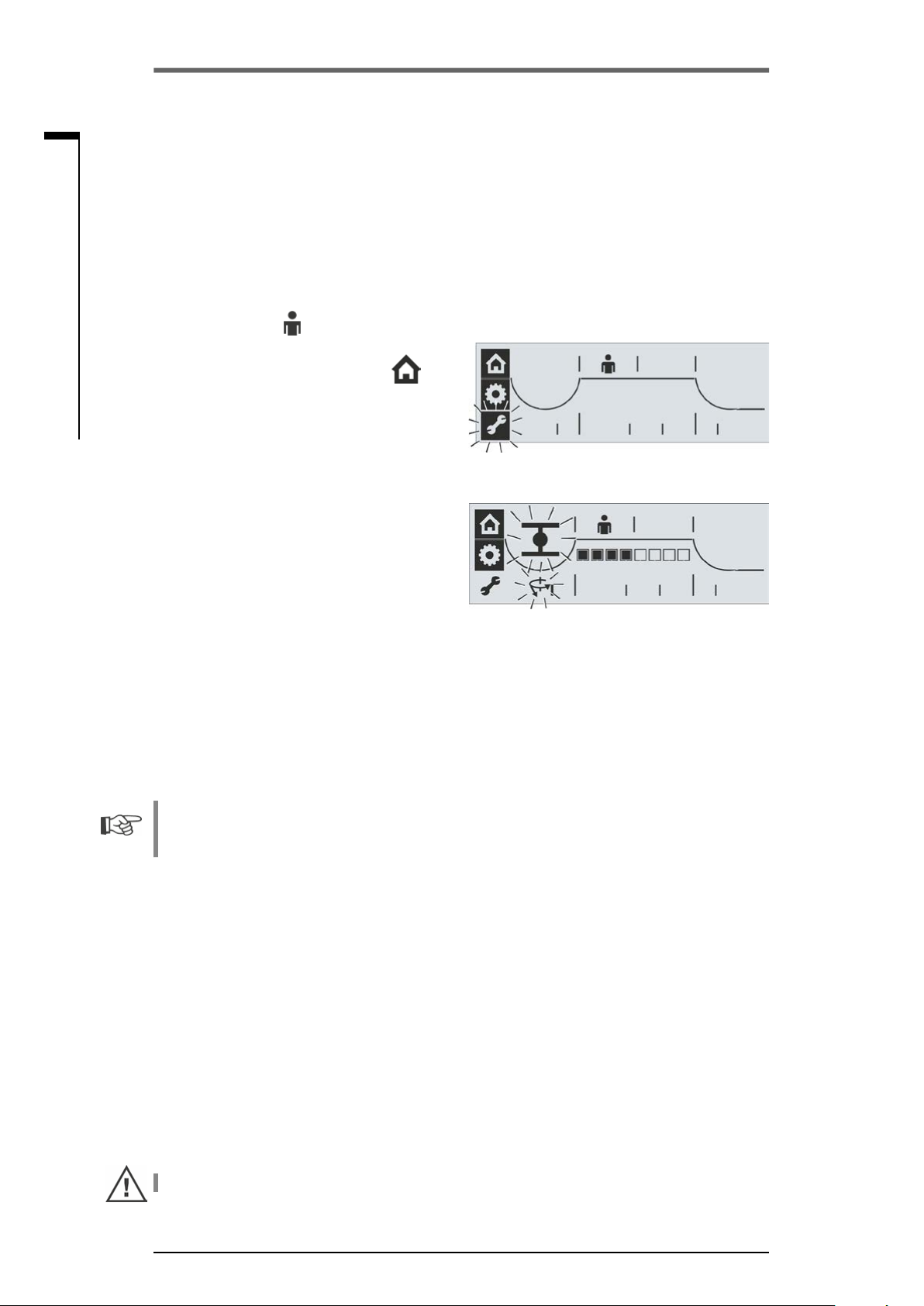
5�3�1 Access to the Parameter menu
1. Change to the ’LOCAL mode‘ state:
a. Select symbol
b. Conrm selection: Press Drive Controller.
2. Select symbol for ‘Local operation‘ Turn
Drive Controller.
The symbol is blinking.
3. Conrm selection: Press Drive Controller.
The ’Local operation‘ symbol is blinking
inversely.
4. Select ‘Parameter’ menu:
Turn Drive Controller until wrench symbols
starts to ash inversely (g. 1).
5. Conrm selection: Press Drive Controller.
The actuator is in the ‘Parameter‘ menu,
the wrench symbol is continuously illuminated and the symbol for the rst parameter is blinking, here torque in end position
CLOSED (g. 2).
Now the individual parameters can be selected
(turn Drive Controller).
: Turn Drive Controller.
Fig� 1: Select Parameter menu
Fig� 2: Parameter menu active
Select and conrm wrench symbol to quit the
‘Parameter’ menu.
5�3�2 Adjust tripping torques
■
For 2SQ7 actuators, the tripping torque can be set at the torque switching mechanism, refer to
supplement to operations instructions Y070.449
■
For 2SG7 actuators, the tripping torque cannot be changed.
Tripping torque
The setting determines the torque to be achieved in relation to the load, to cause the motor to trip.
This applies to torque-dependent tripping in the end position as well as to a block. Therefore, the
tripping torque also has to be adjusted for travel-dependent cut-off mode.
The tripping torque of an actuator is based on the sizing, dened by the application. The tripping
torque range of the actuator is listed on the name plate.
For
■
actuators of duty classes A (OPEN-CLOSE duty) and B (inching/positioning duty) between
30 – 100 % and for
■
actuators of duty class C (modulation duty) between 50 – 100 %,
the tripping torque can be set in steps of 10% of the max. torque. Default setting is the lowest
possible value (typically 30 % of the maximum value for classes A and B, and 50 % of the maximum
value for class C).
The following table shows the possible setting values.
If a cut-off mode is selected that is not appropriate for the valve, the valve may be damaged!
Page 28 Y070.301/EN

Operation instructions
SIPOS SEVEN ECOTRON
5 Commissioning
Tripping torques
Tripping range
[Nm]
Indication in the
display ►
Classes A and B (type of duty in compliance with EN 15714-2) – 2SA70���/2SA73���
9 – 30 9 12 15 18 21 24 27 30
18 – 60 18 24 30 36 42 48 54 60
37 – 125 37 50 62 75 87 100 112 125
75 – 250 75 100 125 150 175 200 225 250
150 – 500 150 200 250 300 350 400 450 500
300 – 1,000 300 400 500 600 700 800 900 1,000
600 – 2,000 600 800 1,000 1200 1400 1600 1800 2000
1200 – 4,000 1200 1600 2000 2400 2800 3200 3600 4000
Class C (type of duty in compliance with European Standard EN 15714-2) – 2SA75���
10 – 20 10 12 14 16 18 20
20 – 40 20 24 28 32 36 40
40 – 80 40 48 56 64 72 80
87 – 175 87 105 122 140 157 175
175 – 350 175 210 245 280 315 350
350 – 700 350 420 490 560 630 700
700 – 1,400 700 840 980 1120 1260 1400
1400 – 2,800 1400 1680 1960 2240 2520 2800
30 % 40 % 50 % 60 % 70 % 80 % 90 % 100 %
■□□□□□□□ ■■□□□□□□ ■■■□□□□□ ■■■■□□□□ ■■■■■□□□ ■■■■■■□□ ■■■■■■■□ ■■■■■■■■
▲30 % are set as standard
Possible values for setting in Nm of Md
▲50 % are set as standard
max
5
Commissioning
Operation sequence
1. Call up ’Parameter‘ menu; the wrench
symbol
„5.3.1 Access to the Parameter menu“
on page 28.
2. Conrm; press Drive Controller.
The symbol for tripping torque (1) in end
position CLOSED (2), both blinking, as
well as the scale (4) with the setting range
between 30 % and 100 % will be displayed.
The segments (black triangles) (3) indicate
the current setting, one segment represents
a step of 10 %. The illustration on the right
indicates that the adjusted tripping torque
amounts to 60 % of the maximum torque.
3. To change the indicated setting, press the
Drive Controller.
The symbols for tripping torque and
end position CLOSED are continuously
illuminated and the black segments of the
scale are blinking.
4. Turn Drive Controller, to change the setting
(for actuator classes A and B: 30 % – 100 %;
for actuator class C: 50 % – 100 %).
For the setting values per level, refer to the
table above.
The scale (g. 2, item 1) indicates the modication.
5. Press Drive Controller; the changed setting
is accepted and the symbols for end position
CLOSED and tripping torque will be ashing
again.
Proceed accordingly to set tripping torque in end
position OPEN. Select the symbol for tripping
torque in end position OPEN (g. 3, item 1) and
continue from step 3 as described above.
is blinking. Refer also to
Fig� 1: Set tripping torque in end position
CLOSED
Fig� 2: Tripping torque scale
Fig� 3: Tripping torque in end position
OPEN
Y070.301/EN Page 29

Operation instructions
5 Commissioning
SIPOS SEVEN ECOTRON
5
Commissioning
5�3�3 Adjust speeds/positioning times
Adjust the speed/positioning time to dene the speed at which the actuator is operated. Depending
on the actuator type, different values can be set for speed/positioning time, refer to table below (actuator type and the adjustable speed range is also indicated on the name plate). New actuators are
set in the factory. Unless requested otherwise by the customer, the default parameter for CLOSE
and OPEN directions is level 4 of the 7-level setting range (step-up factor: 1.4).
If the current values are to be retained, continue with chapter „5.3.4 Select output signal set“ on
page 31.
Speed
ranges
Indication in the
display ►
1,25 – 10 1.25 1.75 2.5 3�5 5 7 10
2,5 – 20 2.5 3.5 5 7 10 14 20
5 – 28 5 7 10 14 20 28 --5 – 40 5 7 10 14 20 28 40
10 – 80 10 14 20 28 40 56 80
20 – 112 20 28 40 56 80 11 2 ---
20 – 160 20 28 40 56 80 112 160
Positioning time
range
80 – 10 80 56 40 28 20 14 10
■□□□□□□□ ■■□□□□□□ ■■■□□□□□ ■■■■□□□□ ■■■■■□□□ ■■■■■■□□ ■■■■■■■□
Positioning time for part-turn actuator 2SG7 and 2SQ7
Possible values for speed [rpm]
Possible values for positioning time [s/90°]
Operation sequence
The actuator is in the ‘Parameter‘ menu.
1. Turn Drive Controller until symbol for speed
is blinking (g. 1, item 2).
The black segment in the scale, g. 1,
item 1, indicates the currently set speed/positioning time level, see also table above.
2. Press Drive Controller.
The black segments in the scale are
blinking (g. 2).
3. Turn Drive Controller and selected desired
speed/positioning time level.
The scale indicates the selected level (g. 2,
item 1).
4. Press Drive Controller.
The parameter value of the selected level is
accepted and the speed symbol is blinking.
Now, one of the 4 output signal sets can be
selected. Turn Drive Controller until the symbol
for signal set is indicated.
▲
Level 4 is set as standard.
Fig� 1: Speed/positioning time level
Fig� 2: Change speed/positioning time level
Page 30 Y070.301/EN

Operation instructions
SIPOS SEVEN ECOTRON
5�3�4 Select output signal set
You may dene which output signals are present at the 5 signal outputs. You may choose between
4 output signal sets (consisting of predened output signals for each of the 5 signaling outputs).
Output signal
sets
Indications on
display
Set 1
(defaut setting)
■□□□□□□□
Set 2
□■□□□□□□
Set 3
□□■□□□□□
Set 4
□□□■□□□□
* H = active high: supply voltage binary output,
L = active low: 0 V).
Level active high or active low is set when reaching the status.
** for 2SG7... “Fault motor temperature”
Level*
outputs
Signaling
H a Travel OPEN
1
H b Travel CLOSE
2
L c Torque OPEN/CLOSE reached
3
H d Ready + REMOTE
4
L e Warning motor temperature**
5
H f End position OPEN
1
H g End position CLOSED
2
H h Blinker
3
H d Ready + REMOTE
4
L i Warning motor temperature**
5
H f End position OPEN
1
H g End position CLOSED
2
L j Fault
3
H k Local
4
L i Warning motor temperature**
5
H a Travel OPEN
1
H b Travel CLOSE
2
H d Ready + REMOTE
3
L l Torque OPEN reached
4
L m Torque CLOSE reached
5
Signal Explanation
5 Commissioning
a Travel OPEN:
For travel-dependent cut-off in position 100 % OPEN;
for torque-dependent cut-off in position >= 98 % OPEN.
b Travel CLOSE:
For travel-dependent cut-off in position 0 % ;
for torque-dependent cut-off in position >= 2 % OPEN.
c Torque OPEN/CLOSED reached:
For torque-dependent cut-off within end position range OPEN
or CLOSED.
Ready + REMOTE
d
If the actuator can be operated from REMOTE.
e Warning motor temp�:
If the set motor warning temperature (default: 135 °C) has
been reached.
f, g End position OPEN, end position CLOSED:
For travel-dependent cut-off in position 100 % OPEN/ 0 %
OPEN.
For torque-dependent cut-off,
if tripping torque within end position range (>= 98 % OPEN/
<= 2 % OPEN) is reached.
h Blinker:
0.5 Hz-change between high/low level if the actuator is
operated (low at standstill).
j Fault:
If a fault has occurred.
k Local:
Actuator is in position Local.
Torque OPEN reached:
l
If tripping torque in OPEN direction is reached.
m Torque CLOSE reached:
If tripping torque in CLOSE direction is reached.
5
Commissioning
Operation sequence
1. Turn Drive Controller in the ‘Parameter’
menu until symbol for speed is blinking
(g. 1, item 2).
A black segment indicates the current
set within the rst four digits of the scale
(item 1); in g.1, set 4 is selected (see also
table above).
2. Press Drive Controller.
The black segment, which indicates the ad-
justed output signal set, is ashing (g. 2).
3. Turn Drive Controller and select desired
signaling set (g. 2, item 1).
The segment in the scale indicates the se-
lected output signal set; the rst position on
the left stands for output signal set 1.
4. Press Drive Controller.
The parameter values of the selected output
signal set are accepted and the black
segment for the selected output signal set
is continuously illuminated and the control
mode options are available.
Refer to following section.
Y070.301/EN Page 31
Fig� 1: Indication of output signal sets
Fig� 2: Output signal set selection
Operation instructions
5 Commissioning
SIPOS SEVEN ECOTRON
5
Commissioning
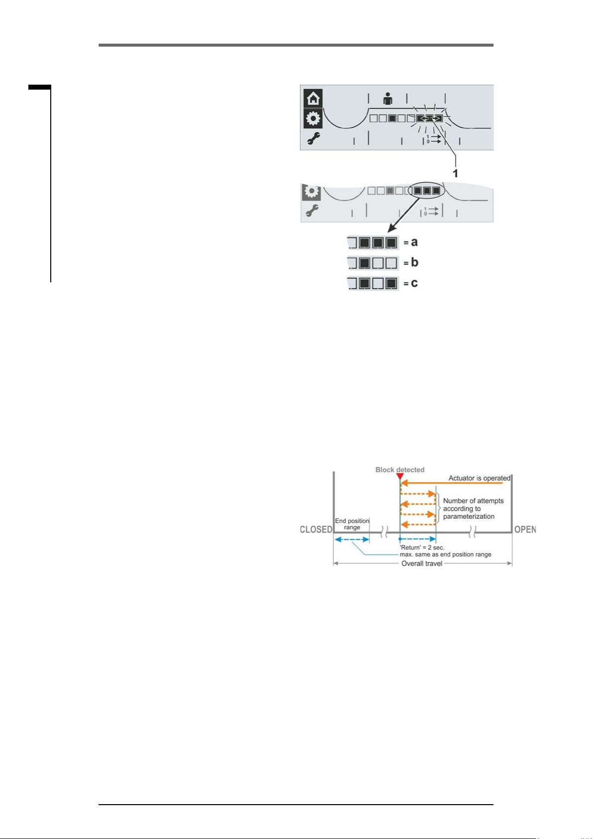
5�3�5 Set control mode
After an output signal set has been selected,
as a next step the setting of the control mode
is enabled; in the display one, two or three
segments will be ashing (see g. 1, item 1).
Operation sequence
1. Turn Drive Controller until the segment(s)
for desired control mode is/are ashing
(see g. 2):
a = Binary: Permanent contact (default
setting)
b = Binary: Pulse contact,
c = Fieldbus: Permanent contact
(only available with eldbus hardware).
2. Press Drive Controller.
The selected control mode is accepted and
the segment(s) for the selected control mode
is/are continuously illuminated.
Fig� 1: Control mode indication
Fig� 2: Control mode selection
5�4 Further settings via COM-SIPOS
Other parameters can be set using the COM-SIPOS PC parameterization program. Some are
described in the following. For further information refer to „4.8 COM-SIPOS PC programming software“ on page 24.
Retry torque block
If the actuator is blocked in move (block outside the end position range), the actuator is tripped and
the red LED ashes periodically 5 times. The actuator is still "ready" since it can still be operated
into the opposite direction.
If the value for the "retry torq.block" parameter
is not equal to zero, the actuator is automatically operated into the opposite direction once
a block has been detected and then again in
the direction of the block. The partial stroke for
this opposite movement will be corresponding
to the setting of the end position range it was
moving to, but not longer than 2 seconds. Then
the movement reverses automatically back. This
happens until the block has been overcome
or the programmed number of tries has been
reached.
Default setting is 0.
Fig�: Retry torque block
Motor temperature warning
A warning is issued once the motor temperature has reached a preset value.
A value between 0 and 155 °C can be set.
The warning signal can be provided via binary signal and eldbus protocol.
Default value is 135 °C.
This parameter is not available for the part-turn actuator 2SG7.
Motor heating
The motor heating can be switched on to prevent condensation. When the heater is activated, the
motor can be heated with DC current. The heating up depends on the difference between motor
temperature and ambient temperature.
The heater is switched off as standard.
If exposed to strong climatic uctuations, the actuator should be operated with the motor heater
switched on.
Page 32 Y070.301/EN

Operation instructions
SIPOS SEVEN ECOTRON
Motor protection
The motor is equipped with full electronic motor protection against thermal damage. The motor
protection is activated in the factory.
5 Commissioning
End position range
Within the end position range, travel is at a low
speed (positioning speed or long positioning
time). In the event of torque dependent actuator
tripping outside this range, a fault is detected
(„Status and fault signals“ on page 17).
5
5�4�1 DC link voltage limitation
During actuator standstill, high connection voltages (operating voltage above the voltage tolerance
of up to +15 %) will increase the DC link voltage, which will be electronically limited to a permissible
value.
Deactivating this function is only useful for very specic plant conditions and should only be performed after consulting SIPOS!
5�4�2 Runtime monitoring
As standard, SEVEN actuators are equipped with runtime monitoring. When running the actuator
for the rst time over a distance of at least 3 % of the entire travel after setting the end positions, the
runtime is measured and stored in a non-volatile memory. The actual motor frequency or speed is
taken into account during the measurements.
During future operation, it will be checked whether the position reached after the runtime is plausible. Tolerances due to different loads and measurement inaccuracies during position measurement
are taken into account. If the expected position is not reached in time, the actuator changes over to
the “fault” state and signals “runtime error”.
This internal monitoring can be deactivated, i.e. exceeding the runtime will not cause a fault signal.
This can prove useful for special applications.
Commissioning
Fig�: End position ranges
Runtime monitoring is activated on delivery.
5�4�3 End position speed
Within the end position ranges, the actuator operates at an end position speed dened for each
device to change to the dened speed when leaving the end positions.
For extremely long total runtimes, it may be desired that the actuator changes as quickly as
possible, even before leaving the end position range to the adjusted, typically high speed. It may,
however, also be required that the actuator operates as long as possible at the dened speed when
approaching the end position to be able to quickly stop in the end position.
Refer also to “End position range“ on the previous page and chapter „Adjust speeds/positioning
times“ on page 30.
Y070.301/EN Page 33

Operation instructions
5 Commissioning
SIPOS SEVEN ECOTRON
5
Commissioning
Normal
for travel and torque-dependent cut-off mode,
the actuator runs
■
from the end position at the lowest speed,
approx .1 sec. (g. 1: curve a), to change to
the end position speed, refer to b;
■
after the end position range with the set
speed. This speed is usually higher than the
end position speed (curve c). It can also be
set lower, refer to curve d.
■
to the end position with the “normal“ end position speed (e).
Quick start
Leaving the end position:
■
For travel-dependent cut-off, it will be immediately changed to the set speed to keep the
runtime as short as possible. Refer to g. 2,
curve a.
■
For torque-dependent cut-off, the end
position is left at the lowest possible speed
for approx. 1 sec. prior to changing to the set
speed; refer to curve b.
Fig� 1: End position speed ’Normal‘
The speed can however be lower than the end
position speed, refer to curve c.
Approaching the end position:
Shortly before reaching the end position range
(independent of the cut-off mode), the speed will
be reduced to the end position speed as for the
“Normal” setting.
Quick start/stop
Leaving the end position is identical to ’Quick
start‘ setting.
Approaching the end position:
■
For travel-dependent cut-off, the speed will
be reduced shortly before reaching the end
position so that the actuator is at standstill;
refer to g. 3, curve a.
■
For torque-dependent cut-off, the speed will
still be changed to the end position speed
before actually reaching the end position
range to avoid excessive torque and potential
damage to the valve, refer to curve b.
End position speed “Normal” is set in the factory.
Fig� 2: End position speed ’Quick start‘
Fig� 3: End position speed ’Quick start/stop‘
Page 34 Y070.301/EN
Operation instructions
SIPOS SEVEN ECOTRON
5�5 Adjust end positions
If actuators are delivered mounted to a valve, this step has been done in the valve manufacturer’s
factory. The setting has to be checked during commissioning.
ECOTRON actuators are available in various versions:
■
using signaling gear or
■
the non-intrusive position encoder
■
2SG7..., 2SQ7... part-turn actuator
End position adjustment differs for the variant with signaling gear. This is indicated in the following
description.
Adjustment of the signaling gear reduction ratio is neither required for the non-intrusive version
nor for 2SG7... and 2SQ7... part-turn actuators. These actuators are not equipped with an
adjustable signaling gear.
5�5�1 Position recording with signaling gear - functional principle
5 Commissioning
5
Commissioning
By setting the signaling gear ratio and the end positions, it is ensured that length as well as start
and end of the valve travel (end positions OPEN and CLOSED) are correctly signaled to the
electronics unit.
Fig�: Schematic representation of the settings: Signaling gear ratio and end positions
Y070.301/EN Page 35

Operation instructions
5 Commissioning
SIPOS SEVEN ECOTRON
5
Commissioning
5�5�2 Sequence during end position adjustment:
Explanation
The signaling gear (7) reduces the rotations of the output shaft (4) required for the complete travel
[(5) X –Y] to a rotary movement of less than one full revolution (max. rotation angle of the potentiometer (x - y) (Setting (a), refer to following chapter, "Adjust signaling gear ratio“).
From the position of the potentiometer, the electronics unit recognizes the position of the output
drive shaft and therefore the position of the connected valve.
To this end, the potentiometer has to be set so that one of the mechanical end positions of the valve
(X or Y) corresponds to one limit of the electric setting range of the potentiometer (x or y) (Setting
(b), refer to the following chapter "Adjust end positions“.)
1. Adjust signaling gear reduction ratio (only for variant with signaling gear).
2. Adjust end positions (“End positions” menu)
a) Select closing direction.
b) Program/adjust rst end position:
– travel or torque dependent cut-off,
– Position of rst end position.
c) Program/adjust second end position:
– travel or torque dependent cut-off,
– Position of second end position.
5�5�3 Adjust signaling gear ratio (version with signaling gear)
The number of revolutions required to cover the whole travel should be known. The data is provided by the valve manufacturer. If this information is not available, see note below. For the required
setting of the signaling gear, refer to the "Signaling gear setting" table below.
Intermediate values of rev/stroke are rounded up to the next incremental value (e.g. for 30 rev/
stroke, the incremental value 36 has to be set).
Signaling gear setting
Actuator type Valve travel rev/stroke
2SA7.1/2/3/4/5/6 0.8 2.1 5.5 14 36* 93 240 610 1575 4020
2SA7.7/8 0.2 0.52 1.37 3.5 9 * 23.2 60 152 393 1005
10 possible settings at
the signaling gear (scale) ►
If the number of revolutions per stroke is not known, because, for example, the actuator is to be
operated on an available "old" valve, operate the actuator over the whole travel and note the number of revolutions of the output drive shaft.
If it is not possible to monitor the output drive shaft, skip this chapter. Observe the note on the
signaling gear in the "Prerequisite for end position adjustment" section in chapter 5.5.4, "Adjust
end positions".
▼ ▼ ▼ ▼ ▼ ▼ ▼ ▼ ▼ ▼
0.8 2.1 5.5 14 36 93 240 610 1575 4020
*Default setting, unless required otherwise by the customer
Page 36 Y070.301/EN

Operation instructions
SIPOS SEVEN ECOTRON
Procedure
1. Loosen 4 screws (item 1)
from the signaling gear cover and remove
cover.
2. Round up rev/stroke to the next incremental
value (for incremental values refer to table
above).
3. Adjust the slide wheel (2) so that the gear rim
faces the desired incremental value on the
scale.
Push the slide wheel in the desired direction,
applying only little pressure.
Adjusting the slide wheel is facilitated by a
slight movement of the central wheel (3).
Do not yet t signaling gear cover.
The end positions have to be set and, if available,
the mechanical position indicator.
5 Commissioning
5
Commissioning
Fig�: Adjust signaling gear ratio
5�5�4 Adjust end positions
The end positions are directly set at the actuator.
Prerequisite for adjustment
■
The valve must not be jammed. Use the crank handle/hand wheel for release, if necessary. For
crank handle operation, refer to chapter “4.1 Crank handle, hand wheel“ on page 14.
■
For version with signaling gear only:
– The signaling gear should be set, refer to previous chapter "Adjust signaling gear ratio".
– If the signaling gear ratio was not set because the number of revolutions/stroke is not known,
proceed nevertheless as described in the following. Observe the note for operation step 15.
■
Abortion of end position setting
– Version with signaling gear: Once the central wheel (friction coupling) has been displaced,
abortion is no longer possible. Turn Drive Controller several times in ccw direction.
– Version without signaling gear:
The former end position setting remains unchanged unless another end position is set.
■
The end positions must not be set according to a specic sequence. The following operation
steps describe end position OPEN adjustment.
Access to the ’End position‘ menu
The ‘End position’ menu can only be accessed
in ‘Local operation’ mode (according to „Access
to the Parameter menu“ on page 28).
1. Select ‘End position’ menu: Turn Drive Controller until the frame of the gear wheel sym-
bol starts to ash (g. 1). Gear wheel symbol
is shown as inverted representation.
2. Conrm selection: Hold down Drive
Controller for approx� 3 s!
Gear wheel is continuously illuminated and
– the symbol of the currently set closing
direction is blinking (g. 2).
– the OPEN symbol is blinking for 2SQ7.
Continue with step 5.
Y070.301/EN Page 37
Fig� 1: Select End position menu
Fig� 2: End position menu is active, ccw
closing direction

Operation instructions
5 Commissioning
SIPOS SEVEN ECOTRON
5
Commissioning
Program closing direction
3. Select closing direction: Turn Drive
Controller.
In the display, the closing direction changes
– in our example from ccw to cw closing
direction (g. 3).
4. Accept selected closing direction: Press
Drive Controller.
The selected closing direction is saved and
the display changes to end position OPEN;
the OPEN symbol starts to ash (g. 4).
Adjust rst end position
5. Select end position to be adjusted rst:
– If end position OPEN is to be adjusted rst,
continue with step 6.
– If end position CLOSED is to be adjusted
rst, turn Drive Controller. The CLOSED
symbol starts to ash.
In our example, end position OPEN (g. 4) is
to be adjusted rst.
6. Conrm selected end position:
Press Drive Controller.
The display changes to cut-off mode adjustment for the selected end position. The
current cut-off mode ashes (g. 5):
= travel dependent
= torque dependent
7. Save cut-off mode:
– Accept displayed cut-off mode: Press
Drive Controller,
or
– change cut-off mode: First turn, then press
Drive Controller.
Fig� 3: End position menu active, cw closing
direction
Fig� 4: End position OPEN is selected
Fig� 5: Indication of active cut-off mode
a = torque dependent
b = travel dependent
Different lines indicate the active cut-off
mode in the display (g. 5):
a = torque dependent
b = travel dependent
8. Signaling gear only: Turn central wheel at
signaling gear to mid position; markers 1
and 2 point in upward direction and the end
position symbol of the selected end position
starts to blink (g. 6).
9. Operate actuator to rst end position: Press
Drive Controller.
The end position symbol is blinking.
If you hold down the Drive Controller for
more than 3 sec., self-retaining starts.
Press Drive Controller once again to stop
operation.
Important: During operation
– heed valve position as well as
– Signaling gear only: heed direction of
rotation of the central wheel (g. 7), this is
important for step 10.
Page 38 Y070.301/EN
Fig� 6: Turn central wheel to mid position
until end position symbol is ashing
Fig� 7: Monitoring direction
of rotation

Operation instructions
SIPOS SEVEN ECOTRON
For travel dependent cut-off mode:
Operate the actuator until the valve has
reached the end position. Changing the
operation direction enables precise end
position adjustment.
For torque dependent cut-off mode: Hold
down Drive Controller for more than 3 s. The
actuator automatically moves until reaching
the end position.
10. Signaling gear only: Slowly turn the central wheel into the same direction as it has
turned when approaching the end position
(refer to “Important” in operation step 9), until
"Save” symbol is shown in the display (g. 8
item a).
If the central wheel has already reached the
stop, turn in the opposite direction.
11. Select Save: Turn Drive Controller until Save
symbol starts to blink, refer to g. 9.
12. Save end positions: Press Drive Controller.
Tick symbol conrms saving of the rst end
position. The display changes to the other
end position (in our example to end position
CLOSED) and for programming the cut-off
mode – the symbol for the currently set cutoff mode, travel or torque dependent, in end
position CLOSED is blinking refer to g. 10.
13. If the actuator is equipped with a mechanical
position indicator, we recommend setting it
now. Separate approaching of the end position can thereby be avoided. For the setting,
refer to the following chapter 5.5.5.
14. Set cut-off mode - ‘travel dependent‘ or
’torque dependent‘- in the second end position (in our example end position CLOSED).
Proceed in the same way as for cut-off mode
adjustment in the rst end position (OPEN).
Follow the instructions of operation step 7.
15. Move actuator to second end position
Refer to operation step 9.
Operate the actuator until the Save symbol
is displayed, refer to g. 11.
Signaling gear only:
If the actuator reaches the end position
before the Save symbol is displayed, the
signaling gear setting has to be changed to
a lower value.
If the central wheel turns to the stop before
reaching the end position, the signaling
gear setting has to be changed to a higher
value.
Repeat complete end position adjustment!
5 Commissioning
5
Commissioning
Fig� 8: Turning central wheel until Save
symbol (a) is displayed
Fig� 9: Saving the end position is active
Fig� 10: Torque dependent cut-off mode
in end position CLOSED
Fig� 11: Operate the actuator until Save
symbol is displayed
Y070.301/EN Page 39

Operation instructions
5 Commissioning
SIPOS SEVEN ECOTRON
5
Commissioning
16. Select Save symbol: Turn Drive Controller
cw until the Save symbol starts to blink,
g. 12.
17. Conrm saving: Press Drive Controller.Two
ticks, refer to g. 13, conrm correct end
position adjustment and the green LED
“Ready” is illuminated.The “End position”
menu symbol is blinking in the display.
18. If the actuator is equipped with a mechanical
position indicator, end position CLOSED of
the mechanical position indicator must be
set, refer to chapter 5.5.5
Fig� 12: Select Save symbol
Now the other menus can be selected (turn
Drive Controller).
After setting the end positions, the central wheel must no longer be moved! Otherwise, the complete end position adjustment must be performed once again.
5�5�5 Adjust mechanical position indicator
The mechanical position indicator indicates
the valve position. The
OPEN and the
to illustration).
The mechanical position indicator is available as
an option (standard for 2SG7... and 2SQ7...).
If the actuator was delivered mounted on a
valve, the setting may already be performed
by the manufacturer. Verifying the adjustment
during commissioning is imperatively required.
If the mechanical position indicator was not yet
set with the end positions, adjust the indicator as
follows.
symbol for CLOSED (refer
Operation sequence
symbol stands for
Fig� 13: Correct end position adjustment
Fig� 1: Position indicator symbols
1. Operate the actuator into the end position
CLOSED.
2. Unscrew signaling gear cover.
3. Turn white disc with CLOSED symbol (g. 2,
item 1), until the symbol and the arrow (3) are
aligned in the indicator glass of the cover.
4. Operate actuator to position OPEN.
5. Hold white disc (1) in position and turn trans-
parent disc (2) so that the OPEN symbol and
the arrow (3) are aligned.
6. Fit signaling gear cover with screws, make
sure the seals have been correctly tted.
Page 40 Y070.301/EN
Fig� 2: Adjust position indicator
Fig� 3: Position indicator for 2SG7
Fig� 4: 2SQ7 position indicator
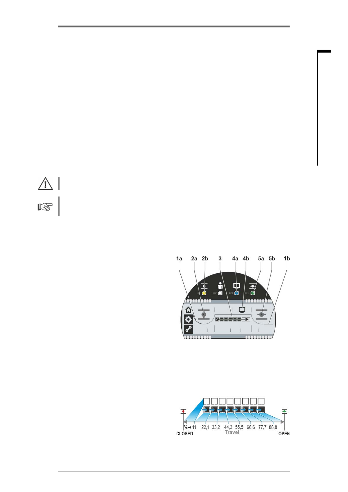
Operation instructions
SIPOS SEVEN ECOTRON
6 REMOTE mode (Remote control)
6�1 REMOTE control
REMOTE control of actuators depends on the automation system and can be performed via
■
Conventional connection
3 binary inputs 24/48 V DC: OPEN, CLOSE and STOP (control is performed via permanent
contact signal)
or
■
Fieldbus (e.g. PROFIBUS DP or MODBUS RTU).
Each actuator (device) on the bus is accessed via its bus address. On delivery, the bus address
is preset for all devices: 126 for PROFIBUS and 247 for MODBUS, unless ordered otherwise
using the programming form, add. version "Y11“.
The operation via a eldbus interface is also described in separate operation instructions, refer
also to chapter 1.5 "Supplementary operation instructions".
The change-over from "REMOTE mode" to "LOCAL mode" can be disabled via eldbus.
An EMERGENCY command received via eldbus will in any case be performed by the actuator,
even if the actuator is subject to conventional (binary) control.
6 REMOTE mode
6
REMOTE mode
If control is to be performed as pulse contact or via eldbus, the control mode has to be set with
the COM-SIPOS PC parameterization program (click ‘REMOTE control‘ in the ’Input/Output‘
tab), or indicated when ordering the actuator.
6�2 Display and LED indications in REMOTE mode
During REMOTE mode, the following actuator
information is displayed:
■
REMOTE LED (g. 1, item 4a) is illuminated
and the REMOTE symbol (item 4b) is
activated in the display.
■
Cut-off mode depending on the end position:
– Torque dependent - bent line (item 1a) or
– Travel dependent - straight line (item 1b).
■
Actuator is in end position CLOSED:
CLOSED symbol (2a) is displayed and the
CLOSED LED (2b) is illuminated.
■
Actuator is in end position OPEN:
OPEN symbol (5b) is displayed and the OPEN
LED (5a) is illuminated.
■
Actuator is in mid-travel:
8-segment position scale (3) indicates the
position in 9 steps, refer to gure 2.
Each segment corresponds to a travel of
approx. 11 %.
Example:
■■■■□□□□
If there is no segment active, the actuator is
between CLOSED and 11 % OPEN.
■
Actuator operation:
Depending on the direction of operation of
the actuator, the respective LED (OPEN or
CLOSE) and the end position symbol in the
display are ashing.
= position OPEN 44.3 – 55.5 %.
Fig� 1: REMOTE mode
Fig� 2: Position scale
Y070.301/EN Page 41

6
Operation instructions
6 REMOTE mode
SIPOS SEVEN ECOTRON
REMOTE mode
6�3 View parameter settings in REMOTE mode
Viewing the parameter settings is possible without interrupting the REMOTE mode. Refer also to
„Check/set parameters“ on page 28.
Operation sequence
The actuator is in REMOTE mode, the
symbol is active and the REMOTE LED is
illuminated.
1. Select ’Local operation‘ menu: Turn Drive
Controller (do not press!) until ‘Local operation’ symbol
2. Conrm selection: Press Drive Controller.
The ’Local operation‘ symbol is ashing
inversely (g. 2).
3. Select ’Parameter‘ menu: Turn Drive
Controller, until the ’Parameter‘ symbol
starts to ash (g. 3).
4. Conrm selection: Press Drive Controller.
The ’Parameter‘ symbol (g. 4, item 1) is
active: both parameters and settings will
be displayed one after the other, refer to
gure 4:
a. Tripping torque in CLOSE direction,
b. Scale; indicates the setting of the
respective parameters,
c. Speed,
d. Output signal set selection for binary
outputs and the control mode,
e. Tripping torque in OPEN direction.
5. Press the Drive Controller to quit the
parameter view.
The ‘Parameter’ symbol is blinking inversely.
Now, the ‘Local operation’ menu can be
selected.
starts to ash.
Fig� 1: REMOTE mode
Fig� 2: Access to the menu
Fig� 3: Select Parameter menu
Fig� 4: View parameters
Page 42 Y070.301/EN

Operation instructions
SIPOS SEVEN ECOTRON
7 Maintenance, inspection, service
7 Maintenance, inspection, service
Before any work is carried out on the actuator, ensure that
■
the planned measures (possible operation of valves, etc.) will not result in injury to persons or
faults in the plant,
■
the actuator or plant section is properly isolated. In addition to the main circuits, also check that
any additional or auxiliary circuits are disconnected!
■
Furthermore, the general safety regulations have to be observed:
– Disconnect all poles (also 24 V DC). This can also be achieved by removing the
connection hood.
– Prevent accidental reconnection.
– Conrm that equipment is not live.
– Ground and short-circuit equipment.
– Fit barriers or covers to neighboring live components.
7�1 General information
7
The actuators are virtually maintenance-free (for relubrication intervals,
refer to chapter „7.2 Lubrication intervals and lubricants“).
We recommend submitting the actuators after commissioning or after approx. 50 operation hours to
a general inspection to verify that
■
correct functioning is guaranteed,
■
no unusual noises/vibration occur,
■
the xing components have not become loose,
■
no leakages occur.
The housing of the SEVEN actuator consists of an aluminum alloy which is corrosion resistant under normal environmental conditions. If the paint was damaged during assembly, it can be touched
up with original paint supplied in small quantity units by the service.
This list cannot cover every eventuality. Further checks may be necessary in accordance with the
plant-specic conditions. Any impermissible deviations or changes detected during inspection must
be rectied immediately.
Under normal operation conditions, service or inspection of the devices is recommended every
8 years, including storage time. The following maintenance work also has to be performed:
■
Replace lubricant within gear housing,
■
replace seals,
■
check all parts within the direct power drive for wear,
■
tighten screw connections of electrical connections.
Depending on the operation conditions, shorter maintenance intervals may be required
Maintenance, inspection, service
This applies in particular to actuators in high temperature version – add. version T09. They have to
be checked for proper condition by the service every 2 years and wear parts have to be replaced!
Replace all seals after continuous immersion within the framework of an inspection.
It is recommended that the services of the local SIPOS Aktorik service center are utilized for this
purpose.
Please contact SIPOS Aktorik GmbH for any service requests. You can nd the address and the
phone number of your competent contact at www�sipos�de. You may also send your requests
directly via e-mail to service@sipos�de.
Y070.301/EN Page 43
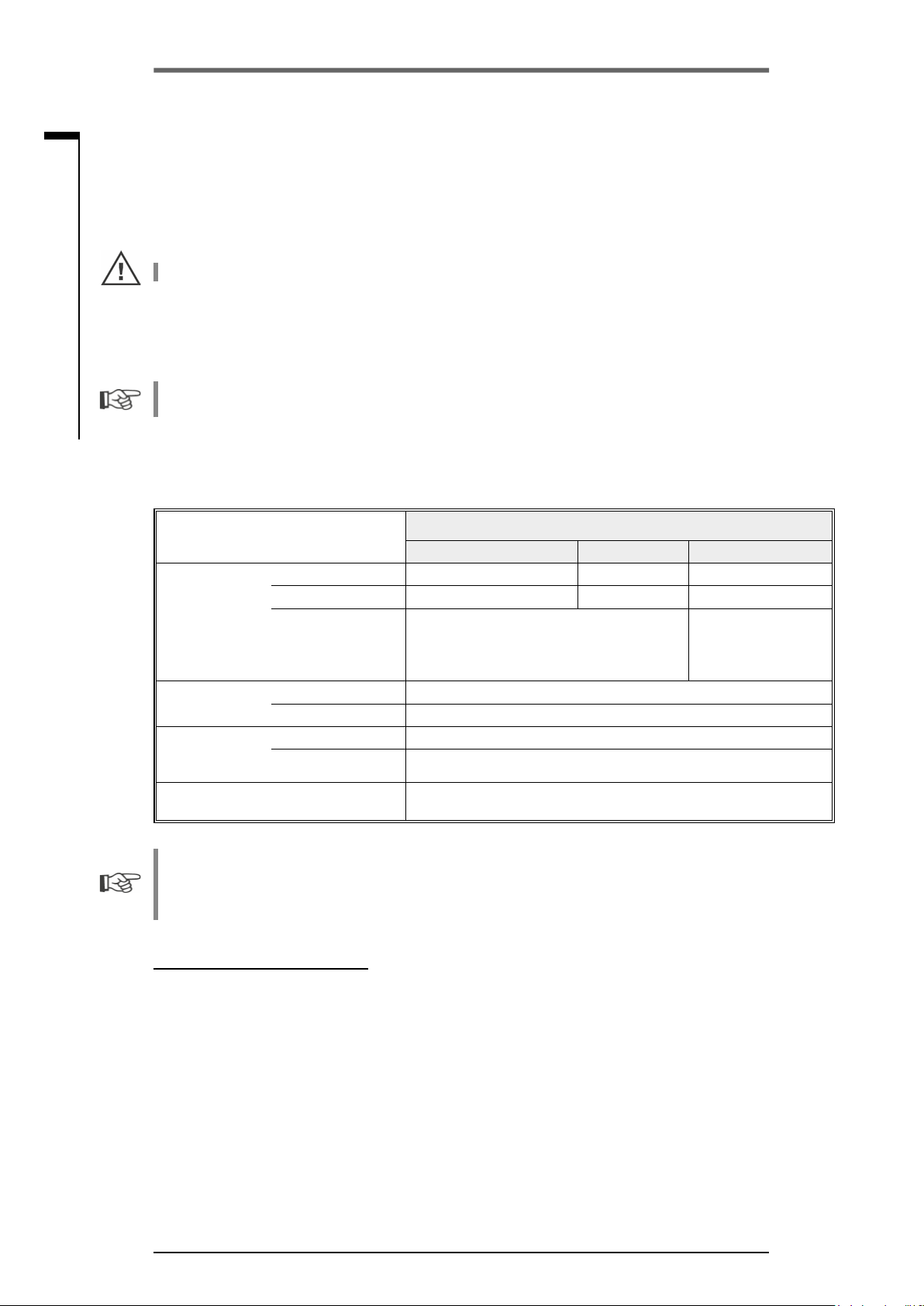
7
Operation instructions
7 Maintenance, inspection, service
SIPOS SEVEN ECOTRON
Maintenance, inspection, service
7�2 Lubrication intervals and lubricants
7�2�1 Lubrication intervals
Perform service or inspection after approx� 8 years (refer to 8.1).
After 50 operating hours or 1 year, regrease coupling shaft A, if available, at the greasing nipple.
For output shaft form A, ensure that the valve stem is greased separately!
These intervals are valid for normal load. When exposed to more intensive loads, the maintenance
intervals are reduced accordingly.
Actuators in high temperature version – add. version T09 – have to be checked for proper condition
by the SIPOS service every 2 years and wear parts have to be replaced!
Whenever the covers and hoods are removed, the seals must be inspected for damage. Replace
and regrease if necessary.
7�2�2 Lubricant assignment and quantity:
2SA7.1/2 2SA7.3/4 2SA7.5/6/7/8
3
Klübersynth GH 6 – 220 N (by Klüber)3 or
Alphasyn PG 220 Polyglycol (by Castrol),
Berusynth EP 220 (by Bechem),
Panolin EP gear synth 220 (by Kleenoil).
3
Lubrication grease AR1 (ZEPF)
3
Commercial ball bearing grease
virtually maintenance-free (The recommendations for the actuators
should also be observed here.)
Gear oil
Other lubrication
4
points
Output shaft type
5
A
(2SA7)
2SG7..., 2SQ7...
part-turn actuator
Lubricant quantity 760 cm
Filling level 1 max. 46 mm max. 58 mm 23 – 27 mm
Lubricant
2
Lubricant quantity 50 cm
Lubricant
2
Lubricant quantity 2 cm
Lubricant
2
Actuator type
1,600 cm
3
2,400 cm
3
Mobil SHC Gear 2203
(refer to identication
at the equipment)
■
The manufacturer's instructions and relevant regulations are to be observed when handling and
disposing of lubricants. Technical information concerning lubricants is available on request.
■
Before using a new alternative lubricant (other than the lubricant lled in the factory), the gear
units and gear parts have to be rinsed and cleaned (avoid mixing the oils).
1
Measured from the lubricant surface to the external wall of the housing at oil lling screw.
2
Ambient temperature range -20 – +60 °C.
3
Lubricant used in the factory.
4
e.g. sealing rings, gear systems, bearings, feather keys, uncoated surface etc.
5
If applied.
Page 44 Y070.301/EN
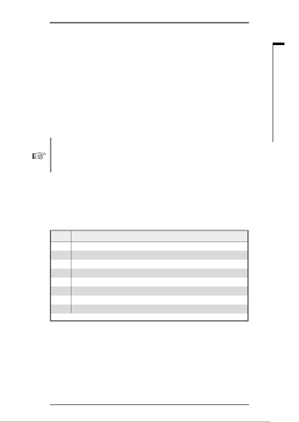
Operation instructions
SIPOS SEVEN ECOTRON
8 Spare parts
8�1 General information
With the exception of standardized, generally available components, only original spare parts may
be used. Spare parts are usually supplied as complete sub-assemblies (see list below). In the
following representation drawings, designations with 3 digits are listed. These numbers are prexed
with "2SY7" to give the full spare parts designation.
When ordering spare parts, always provide the following information:
1. Order number and serial number of the actuator (refer to name plate),
2. Spare parts designation 2SY7 . . . (refer to following list),
3. Quantity required.
■
All external metallic housing parts are made of a corrosion resistant aluminum alloy, painted
with color similar to RAL 7037 (silver-gray) as standard and meet the requirements up to
corrosivity category C5.
■
Other nish paint color ► add. version Y35
■
Very high corrosion protection
corrosivity category C5 with long protection duration ► add. version L38
8 Spare parts
8
Spare parts
8�2 Spare parts list
SEVEN actuators are designed for fault-free operation within the maintenance intervals. As we
know from experience, external causes may damage the actuator already during commissioning
stage. For such events, the recommended spare parts are listed in the following table. If you require
other parts, please contact the Service department.
No� Designation
2SY7001 Electronics unit (010 – 042)
2SY7041 Cover for electronic housing
2SY7218 Sealing kit (without illustration)
2SY7219 Non-intrusive position encoder (niP)
2SY7220 Signaling gear
2SY7225 Signaling gear cover
2SY7250 Manual drive
2SY7252 Handle
▲▲▲ = The last three digits indicate the part numbers in the exploded views.
Y070.301/EN Page 45
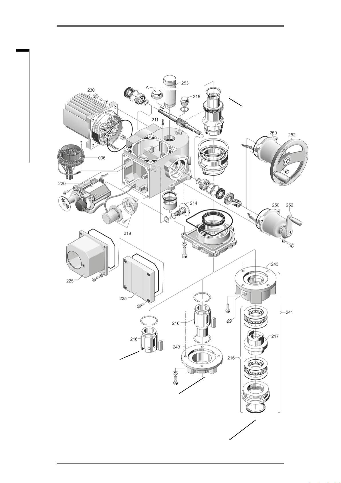
8
Operation instructions
8 Spare parts
SIPOS SEVEN ECOTRON
Spare parts
8�3 Exploded views
8�3�1 Gear unit 2SA7�1/2/3/4�-
Output shaft B1
Output shaft
insert
Reducing ange
Output shaft A
Page 46 Y070.301/EN

Operation instructions
SIPOS SEVEN ECOTRON
8�3�2 Gear unit 2SA7�5/6/7/8�-
8 Spare parts
8
Spare parts
Y070.301/EN Page 47
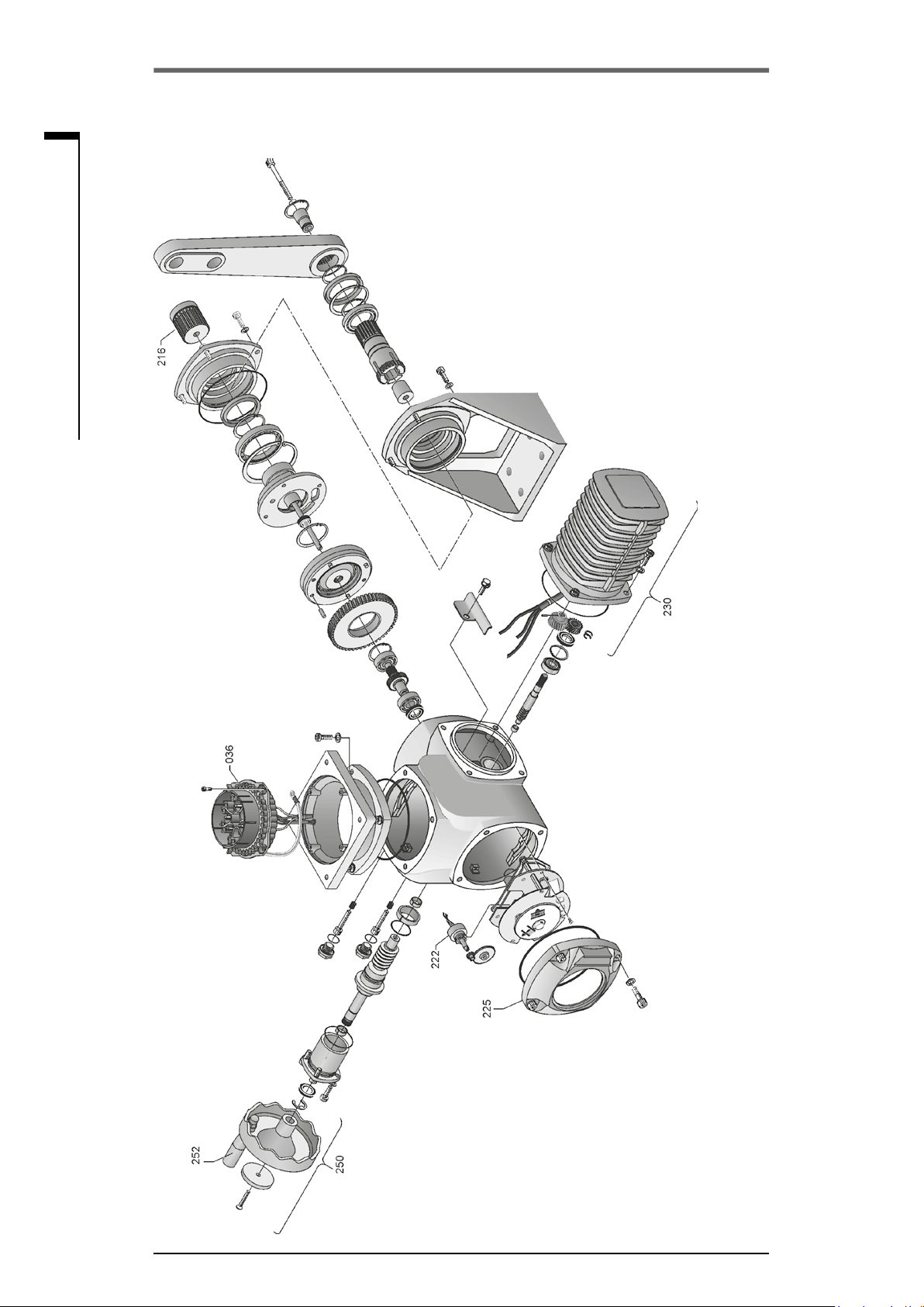
Operation instructions
8 Spare parts
SIPOS SEVEN ECOTRON
8
Spare parts
8�3�3 Small part-turn gear unit 2SG7���-
Page 48 Y070.301/EN

Operation instructions
SIPOS SEVEN ECOTRON
8�3�4 Small part-turn gear unit 2SQ7���-
8 Spare parts
8
Spare parts
Y070.301/EN Page 49
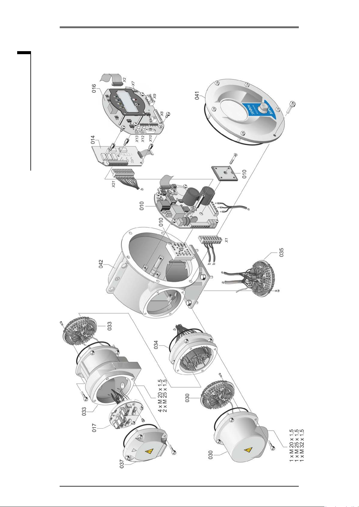
Operation instructions
8 Spare parts
SIPOS SEVEN ECOTRON
8
Spare parts
8�3�5 Electronics unit (motor up to 1�5 kW)
Page 50 Y070.301/EN
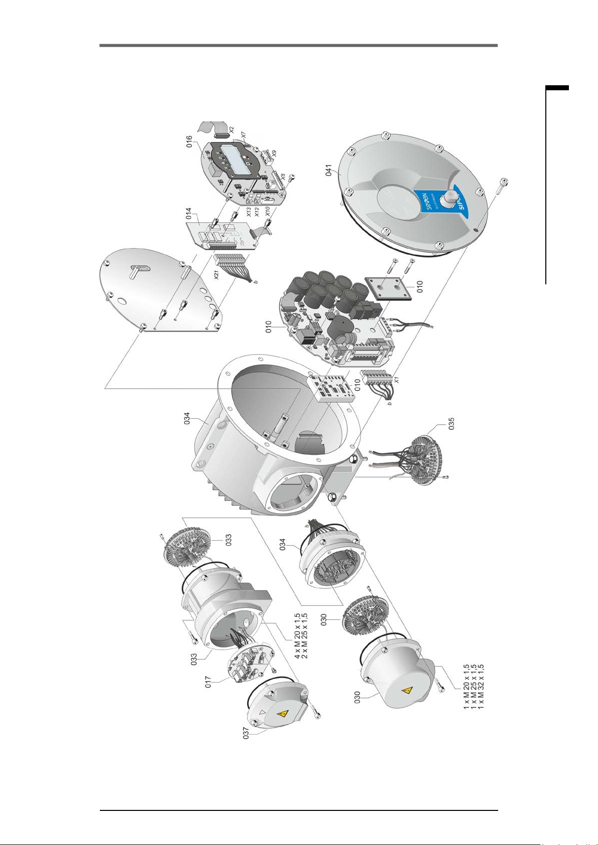
Operation instructions
SIPOS SEVEN ECOTRON
8�3�6 Electronics unit (motor from 3 kW)
8 Spare parts
8
Spare parts
Y070.301/EN Page 51

9
Operation instructions
9 Index
SIPOS SEVEN ECOTRON
Index
Index
A
Adjustment
Set control mode. .................. 32
Analog inputs. ........................ 8
Assembly kit for separate mounting. ..... 13
B
Binary permanent contact. ............. 32
Binary pulse contact. ................. 32
Block diagram. ....................... 8
C
Cable glands. ....................... 11
Central wheel. . . . . . . . . . . . . . . . . . . . . . . . 35
Check/set parameters. ................ 28
CLOSE direction. ................. 35, 38
Commissioning. .................. 25, 26
General information. ................ 25
Prerequisites. ..................... 25
Sequence of the measures. .......... 26
COM-SIPOS. ....................... 24
Connection
Fieldbus. ......................... 12
Potential conductor. . . . . . . . . . . . . . . . . . 12
Connection with round plug. ............ 11
Control board. ..........................
. . . . . . . . . . .see Electronics unit sub-assembly
Crank handle. ....................... 14
Danger of crushing. ..see Safety instructions
Operation. ........................ 14
D
DC link voltage. ..................... 33
DC link voltage limitation. .............. 33
Degrees. ...............see Signaling gear
Display. ............................ 19
Cut-off mode. ..................... 38
Fault. ............................ 17
LEDs. ........................... 15
Navigation. ....................... 20
Symbols. ......................... 20
Valve position. .................. 21, 40
Disposal. ............................ 4
Drive Controller. ..................... 20
E
Electrical connection. ................. 11
Connection with round plug. .......... 11
Fieldbus connection. ................ 12
Electrical connections. ....see Block diagram
Electronics unit. ...................... 7
. . . . . . . . . . . . . . . . . . see also Exploded views
End position adjustment. .............. 35
Versions. ......................... 35
End position speed. .................. 33
Exploded views. ..................... 46
Electronics unit. .................... 50
Gear unit. ........................ 46
F
Fault signals. .................... 15, 17
Fieldbus. ........................... 41
Fieldbus board. .........................
. . . . . . . . . see Electronics unit sub-assemblies
Fieldbus permanent contact. ........... 32
Functional principle. ................... 6
Block diagram. ..................... 8
non-intrusive position encoder. ......... 6
Position recording with signaling gear
functional principle. ................. 35
Signaling gear. ..................... 6
G
Gear unit. ........................... 7
. . . . . . . . . . . . . . . . . . see also Exploded views
H
Hand wheel. ........................ 14
Heater. ................ see Motor heating
I
Inspection. ......................... 43
L
Light emitting diodes (LED). ............ 15
Status and fault signals. ............. 17
‘Local’ actuator operation. ............. 22
Local operation. .................. 22, 23
Lubricants. ......................... 44
Lubricant quantities. ................ 44
Lubrication intervals. ................ 44
Page 52 Y070.301/EN

Operation instructions
SIPOS SEVEN ECOTRON
9 Index
9
M
Maintenance. .................... 19, 43
Mechanical connection. ................ 9
Menu
End positions. .................. 22, 37
Local operation. . . . . . . . . . . . . . . . . . . . . 21
Parameter. . . . . . . . . . . . . . . . . . . . . . 22, 28
Menu structure. . . . . . . . . . . . . . . . . . . . . . . 20
MODBUS. .......................... 41
MODBUS operation instructions. ......... 5
Motor heating. . . . . . . . . . . . . . . . . . . . . . . . 32
Motor protection. . . . . . . . . . . . . . . . . . . . . . 33
Motor temperature warning. ............ 32
Mount electronics and gear unit separately. 13
N
Navigation in the display. .............. 20
Non-intrusive position encoder. .......... 6
O
Operation
Crank handle. ..................... 14
Hand wheel. ...................... 14
Local actuator operation. . . . . . . . . . . . . . 22
Navigation through the menus. ........ 20
Remote control. .................... 41
Output shaft. .................... 6, 9, 47
Drawing. ......................... 47
General assembly instructions. ......... 9
Type A. ........................... 9
Output signal sets. ................... 31
Overview
Display symbols. ................... 20
Menu structure. .................... 20
P
Packaging. .......................... 4
Part-turn actuator 2SQ7
Manual operation. .................. 14
Position indicator. .................. 40
Positioning time. ................... 30
Spare parts. . . . . . . . . . . . . . . . . . . . . . . . 49
Permanent contact. .................. 32
Position. ............................ 8
Position indicator. .............. 21, 39, 40
Positioning times. .................... 30
Potential conductor connection. ......... 12
Potentiometer. ....................... 6
Power module. .........................
. . . . . . . . . see Electronics unit sub-assemblies
PROFIBUS. ........................ 41
Pulse contact. ....................... 32
Q
Quick start. ...................... 33, 34
Quick start/stop. ..................... 33
R
Ready. ............................ 17
Recommended spare parts. ............ 45
Relay board
Electronics unit sub-assemblies. ........ 7
Exploded view. .................... 50
Remote control. ..................... 41
COM-SIPOS. ...................... 24
REMOTE mode. ..................... 41
Indications in the display. ............ 41
Viewing parameters. ................ 42
Retry torque block. ................... 32
Revs/stroke. ............see Signaling gear
Round plug. ........................ 11
Runtime monitoring. .................. 33
S
Safety information. .................... 3
Safety instructions. .................... 3
Maintenance. . . . . . . . . . . . . . . . . . . . . . . 43
Separate mounting. .................. 13
Cable lengths. ..................... 13
Specication. ...................... 13
Service. . . . . . . . . . . . . . . . . . . . . . . . . . . . . 43
Set control mode. .................... 32
Setting
End position adjustment. ............. 35
Parameter. . . . . . . . . . . . . . . . . . . . . . . . . 28
Index
Y070.301/EN Page 53

9
Index
Operation instructions
9 Index
SIPOS SEVEN ECOTRON
Signal cable. ........................ 11
Signaling gear. ....................... 6
Prerequisite for adjustment. .......... 36
Transmission ratio. ................. 36
Transmission ratio adjustment. ........ 36
Signaling gear ratio. .................. 36
Signals
Status. ........................ 16, 17
Spare parts. ........................ 45
Spare parts list. . . . . . . . . . . . . . . . . . . . . . . 45
Special parameters
DC link voltage limitation. ............ 33
End position speed. . . . . . . . . . . . . . . . . . 33
Runtime monitoring. ................ 33
Speed. ..................... see Speeds
Speed in end positions. ............... 33
Speeds. ........................... 30
State indications. ................. 16, 17
Status and fault signals. ............... 17
Status indication (LED). ............... 16
Stem protection tube. .............. 10, 13
Storage. ............................ 4
Storage temperature. .................. 4
Sub-assemblies. ...................... 7
Electronics unit. ..................... 7
Gear unit. ......................... 7
Supplementary operation instructions. ..... 5
Symbols. ............................ 4
Electrostatics. ...................... 4
In the display. ..................... 19
LEDs. ........................... 15
Notice. ............................ 4
Warning. .......................... 4
Working steps by valve manufacturers. .. 4
Symbols in display. ................... 19
T
Temperature during storage. ............ 4
Transport. ........................... 4
Tripping torque. ..................... 28
U
USB port. .......................... 24
V
Valve travel. ........................ 36
Viewing parameter settings. ............ 42
W
Warnings on the device. ................ 3
Page 54 Y070.301/EN

EU Declaration of conformity/Declaration of incorporation
in accordance with Machinery Directive
for electric actuators of the following type designations:
2SA5…, 2SB5…, 2SC5…, 2SG5…
2SA7..., 2SG7…, 2SQ7...
in versions:
ECOTRON
PROFITRON
HiMod
SIPOS Aktorik GmbH as manufacturer declares herewith that the above mentioned actuators meet the basic
requirements of the following Directives:
2014/30/EU (EMC Directive)
2006/42/EC (Machinery Directive)
The following harmonized standards in terms of the specied directives have been applied:
Directive 2014/30/EU
EN 61800-3: 2004 /A1: 2012
Directive 2006/42/EC
EN ISO 12100:2010
EN ISO 5210:1996
EN ISO 5211:2001
DIN 3358:1982
SIPOS actuators are designed for the operation of industrial valves. Putting into service is prohibited until the
nal machinery has been declared in conformity with the provisions of Directive 2006/42/EC.
The following basic requirements in compliance with Annex I of the Directive are respected:
Annex I, articles 1.1.2, 1.1.3, 1.1.5, 1.2.1, 1.2.6, 1.3.1, 1.3.7, 1.5.1, 1.6.3, 1.7.1, 1.7.3, 1.7.4
The manufacturer shall be obligated to electronically submit the documents for the partly completed machinery to national authorities on request. The relevant technical documentation pertaining to the machinery
described in Annex VII, part B has been prepared.
Authorized person for documentation: Dr. Thomas Suckut, Im Erlet 2, 90518 Altdorf, Germany
Furthermore, the essential health and safety requirements in compliance with Directive 2014/35/EU (Low
Voltage Directive) are fullled by applying the following harmonized standards, as far as applicable for the
products:
EN 60204-1:2006 / A1:2009 / AC:2010
EN 60034-1:2010 / AC:2010
EN 50178:1997
Altdorf, 2017-07-18
Dr. Thomas Suckut
Managing Director
This declaration does not contain any guarantees. The safety instructions in product documentation supplied with the devices
must be observed. This declaration shall lose its validity in the event of unauthorized modication of the equipment.
Certicates are valid as from the indicated date of issue. Subject to changes without notice! The
latest versions are available for download at http://www.sipos.de.
Y070.301/EN Page 55

Issue: 11.18 Y070.301/EN
Subject to changes without notice!
© SIPOS Aktorik GmbH
Im Erlet 2 - D-90518 Altdorf
www.sipos.de
 Loading...