

Page 1
SPA2 SIP Gateway User Manual
Document VER
Firmware VER
Explanation
Time
V1.0
2.1.1.2545
Initial issue
20170518
Page 2

Safety Notices
1. Please use the specified power adapter. If you need to use the power adapter provided by other
manufacturers under special circumstances, please make sure that the voltage and current provided is
in accordance with the requirements of this product, meanwhile, please use the safety certificated
products, otherwise may cause fire or get an electric shock.
2. When using this product, please do not damage the power cord either by forcefully twist it, stretch
pull, banding or put it under heavy pressure or between items, otherwise it may cause damage to the
power cord, lead to fire or get an electric shock.
3. Before using, please confirm that the temperature and environment is humidity suitable for the
product to work. (Move the product from air conditioning room to natural temperature, which may
cause this product surface or internal components produce condense water vapor, please open power
use it after waiting for this product is natural drying).
4. Please do not let non-technical staff to remove or repair. Improper repair may cause electric shock,
fire, malfunction, etc. It would lead to injury accident or cause damage to your product.
5. Do not use fingers, pins, wire, other metal objects or foreign body into the vents and gaps. It may
cause current through the metal or foreign body, which may even cause electric shock or injury
accident. If any foreign body or objection falls into the product please stop using.
6. Please do not discard the packing bags or store in places where children could reach, if children trap
his head with it, may cause nose and mouth blocked, and even lead to suffocation.
7. Please use this product with normal usage and operating, in bad posture for a long time to use this
product may affect your health.
8. Please read the above safety notices before installing or using this phone. They are crucial for the safe
and reliable operation of the device.
Page 3

Directory
I. PRODUCT INTRODUCTION ................................................................................................................ 6
1. APPEARANCE OF THE PRODUCT .............................................................................................................. 6
2. DESCRIPTION .................................................................................................................................... 6
II. START USING .................................................................................................................................... 7
1. CONFIRM THE CONNECTION .................................................................................................................. 7
2. QUICK SETTING ................................................................................................................................. 8
III. BASIC OPERATION ......................................................................................................................... 9
1. ANSWER A CALL ................................................................................................................................ 9
2. CALL .............................................................................................................................................. 9
3. END CALL ......................................................................................................................................... 9
4. SECURITY LINKAGE ............................................................................................................................. 9
5. VIDEO LINKAGE ................................................................................................................................. 9
IV. PAGE SETTINGS ........................................................................................................................... 10
1. BROWSER CONFIGURATION ................................................................................................................ 10
2. PASSWORD CONFIGURATION .............................................................................................................. 10
3. CONFIGURATION VIA WEB ................................................................................................................. 10
(1) System ................................................................................................................................. 10
a) Information .......................................................................................................................... 10
b) Account ..................................................................................................... 错误!未定义书签。
c) Configurations ...................................................................................................................... 12
d) Upgrade ............................................................................................................................... 12
e) Auto Provision ...................................................................................................................... 13
f) FDMS ................................................................................................................................... 14
g) Tools .................................................................................................................................... 15
(2) Network ............................................................................................................................... 16
a) Basic .................................................................................................................................... 16
b) VPN ...................................................................................................................................... 17
(3) Line ...................................................................................................................................... 18
a) SIP ....................................................................................................................................... 18
b) Basic Settings ....................................................................................................................... 23
(4) Intercom settings ................................................................................................................. 24
a) Features ............................................................................................................................... 24
b) Audio ................................................................................................................................... 25
c) Video ................................................................................................................................... 26
d) MCAST ................................................................................................................................. 29
e) Action URL ........................................................................................................................... 32
f) Time/Date ............................................................................................................................ 32
(5) Security settings ................................................................................................................... 34
Page 4

(6) Function Key ............................................................................................. 错误!未定义书签。
a) Function Key Settings ........................................................................................................... 35
V. APPENDIX ...................................................................................................................................... 38
1. TECHNICAL PARAMETERS .................................................................................................................... 38
2. BASIC FUNCTIONS ............................................................................................................................ 38
Page 5
6
I. Product introduction
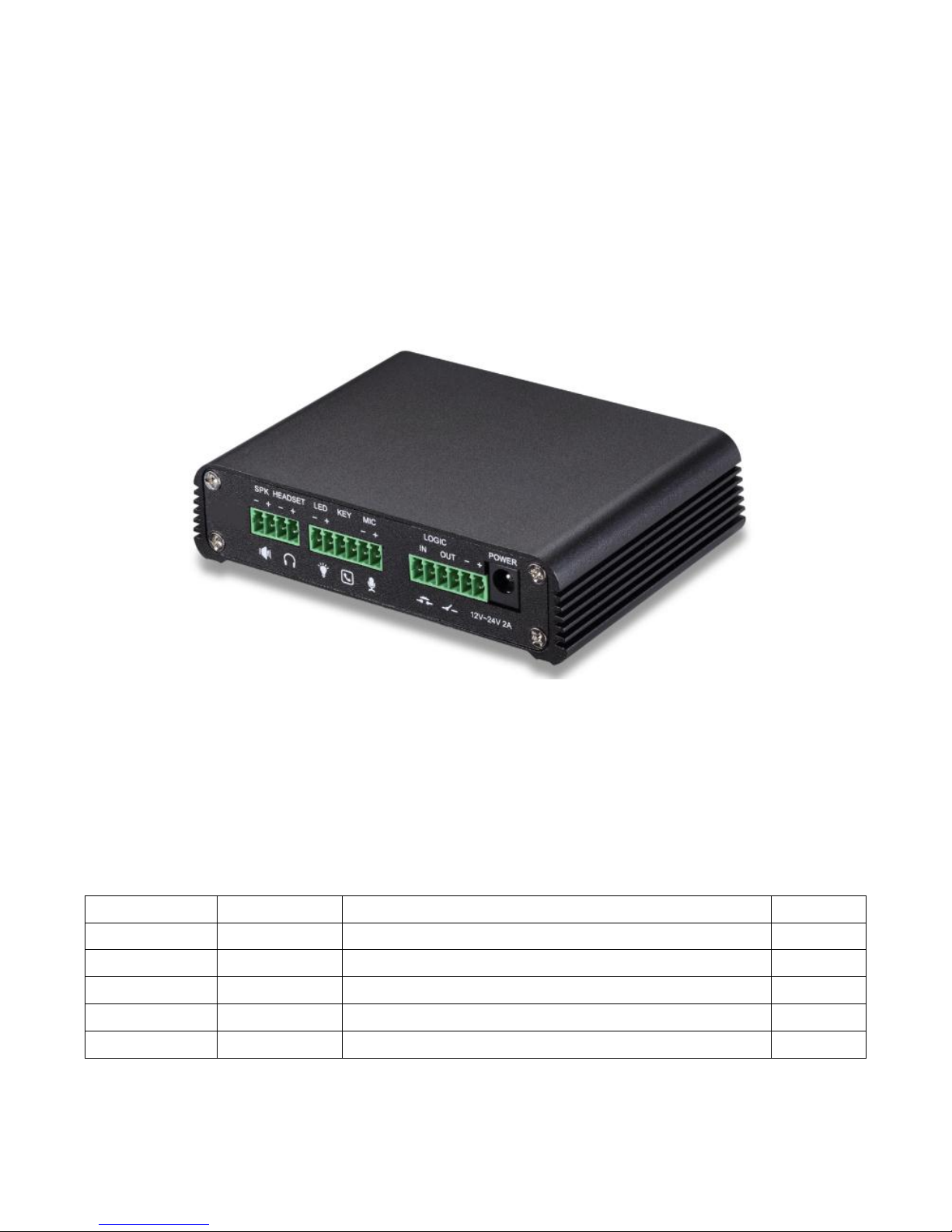
SPA2 is dedicated to the needs of industry users to develop a SIP audio and video intercom,
voice transmission using standard IP / RTP protocol, video transmission using RTSP. It is well inherited
Voptech phone stability, carrier-class sound quality advantages, and perfectly compatible with all
current SIP-based mainstream IPPBX / softswitch / IMS platform, such as Asterisk, Broadsoft, 3CX,
Elastix and so on. It is a variety of functional interface in one, call, radio, video, security, recording, to
adapt to a variety of use of the environment, convenient and rapid deployment of equipment, is ideal
for everyone.
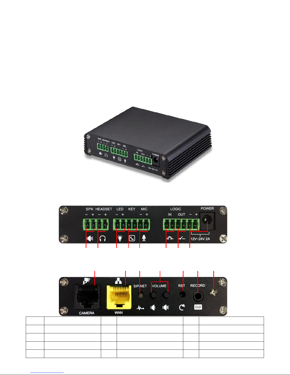
1. Appearance of the product
2. Description
Label
Description
Label
Description
Label
Description
①
Speaker interface
②
Headset interface
③
LED interface
④
Function key interface
⑤
Microphone interface
⑥
Switch input interface
⑦
Switch output interface
⑧
Power input interface
⑨
Camera interface
⑩
Ethernet interface
⑪
Registration/Network LED
⑫
Volume control key
⑪
⑨
⑩
①
⑧
③
②
④
⑤
⑥
⑦
⑭ ⑮ ⑬
⑫
Page 6
7
⑬
Restore factory key
⑭
Recording output interface
⑮
Grounding screw
II. Start Using
Before you start to use the equipment, please make the following installation.
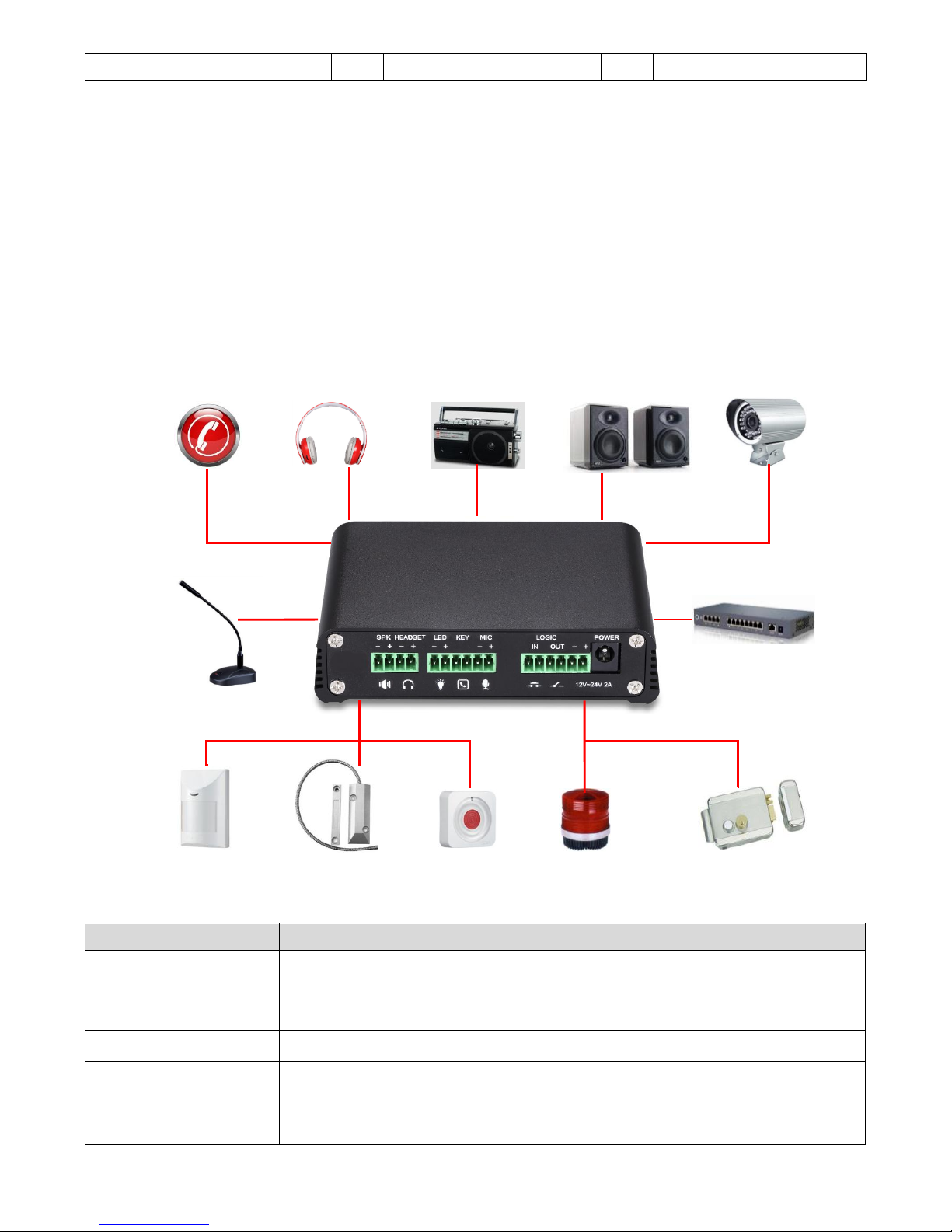
1. Confirm the connection
Confirm whether the equipment of the power cord, network cable and the boot-up is normal. (Check
the network state of light
Label
Explanation
① Speaker interface
according to the device input voltage adaptive output maximum power; 4Ω
speaker, POE / 8W, 12V / 10W, 18V / 20W, 24V / 30W. The greater the horn impedance,
the smaller the output power. Suggested wire diameter: 18AWG or larger diameter.
② Headset interface
speaker audio signal output, for external headset or active speakers.
③ LED interface
5V output, can be an external LED, indicating the network status, call status,
registration status.
④ Function key interface
connection switch, you can log on page set the call number or IP address.
Handsets
recorder
Speaker
Camera
switch
Call button
microphone
Infrared probe
Door sensor
Emergency button
Warning
Electric
⑩
②
⑨
④
③
⑤
⑥
⑦ ⑭ ①
Page 7

8
⑤ Microphone interface
the proposed use of electret condenser microphone, sensitivity: -38dB, bias voltage
2.2V. Microphone signal cable it is recommended to use a shielded cable and connect
the shield cable to the grounding screw, improve anti-interference.
⑥ Switch input interface
Connect an infrared probe or emergency switch or Doorsensor and other switch
components.
⑦ Switch output
interface
corresponding to the short-circuit input interface, login device security page settings,
you can control the alarm light, electric locks and other equipment; with the adjacent
⑧ power port connection for external equipment power supply.
⑧ Power input interface
12V ~ 24V 2A input, according to the input voltage to determine the maximum output
power amplifier.
⑨ Camera interface
standard RJ45 interface, connect the original camera, the proposed use of five or five
sub-network cable
⑩ Ethernet interface
WAN port, standard RJ45 interface, 10 / 100M adaptive, support POE input, it is
recommended to use five or super five network cable.
⑪Registration/Network
LED
indicates network status, call status, registration status. Fast flashing: network anomaly
or SIP account exception. Slow flashing: during a call. Always bright: successful
registration.
⑫Volume control key
standby to adjust the volume of the ringtone, call only adjust the call volume,
broadcast only adjust the broadcast volume. Long press the volume down key to
broadcast the IP address. Long press the volume plus key to switch the IP address
acquisition mode (specific operation see below search door phone).
⑬Restore factory key
press and hold for 3 seconds to flash the device to restart and restore the factory
settings.
⑭Recording output
interface
the local microphone voice and call voice mixed output, suitable for computer and
other equipment recording.
⑮Grounding screw
external parts metal housing needs to be connected to this interface to prevent static
electricity and other interference caused the equipment to work abnormally.
2. Quick Setting
The product provides a complete function and parameter setting. Users may need to have the
network and SIP protocol knowledge to understand the meaning all parameters represent. In order to
let equipment users, enjoy the high quality of voice service and low cost advantage brought by the
device immediately, here we list some basic but necessary setting options in this section to let users
know how to operate device without understanding such complex SIP protocols.
In prior to this step, please make sure your broadband Internet can be normally operated, and
you must complete the connection of the network hardware. The product factory default network
mode is static IP address 192.168.1.128.
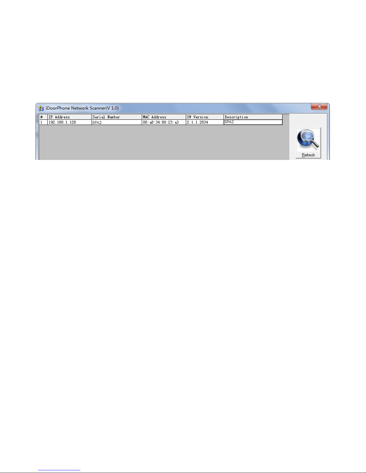
➢ Press and hold volume down key for 3 seconds; the door phone would report the IP address by voice.
Or you can also use the "iDoorPhoneNetworkScanner.exe" software to find the IP address of the
device. (download address www.Voptech.com)
Page 8
9
➢ Long press the volume plus key for 10 seconds, the speaker issued a rapid beep, and then quickly
press the three volumes plus the key, beep stopped. Wait 10 seconds, successfully switch to dynamic
IP after the system automatically voice broadcast IP address. Switching again will become a fixed IP
address.
➢ Note: when the device is powered on, 30s waiting is needed for device running.
➢ Log on to the WEB device configuration.
➢ In a line configuration page, service account, user name, server address and other parameters are
required for server address registration.
III. Basic operation
1. Answer a call
When a call comes in, the device would answer automatically. If you cancel auto answer feature and
set auto answer time, you would hear the ring at the set time and the device would auto answer
after configured timer.
2. Call
Configure Function key as hot key and then set up a number; after that you might press the Function
key for making call to the configured extension(s).
3. End call
Enable Release(You can set Function key to Release)key for hanging up feature to end call.
4. Security linkage
◆ switch input interface received a door or emergency button and other sensor signals, the output
port connected to the alarm lights or electric locks and other equipment will automatically
respond to the server and send alarm information.
◆ The output port defaults to the call automatically triggers the response and supports call
triggering with DTMF number triggering and short message triggering.
5. Video linkage
◆ Use another manufacturers camera please connect to the switch, the device ⑨ interface can
only connect the original camera.
Page 9
10
◆ Landing page configuration camera user name, password, port number and other information. For
more information, please refer to the Video settings
IV. Page settings
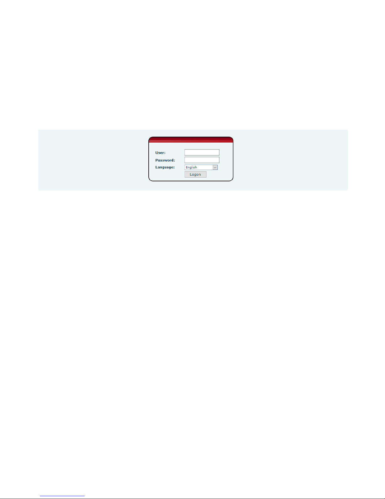
1. Browser configuration
When the device and your computer are successfully connected to the network, you might enter the
IP address of the device in the browser as http://xxx.xxx.xxx.xxx/ and you can see the login interface of the
web page management.
Enter the user admin and password admin and click the Logon button to enter the settings screen.
2. Password Configuration
There are two levels of access: root level and general level. A user with root level can browse and
set all configuration parameters, while a user with general level can set all configuration parameters
except server parameters for SIP.
⚫ General level: It is not be set by default, you can add the feature when you need
⚫ User uses root level by default:
◆ User name: admin
◆ Password: admin
3. Configuration via WEB
(1) System
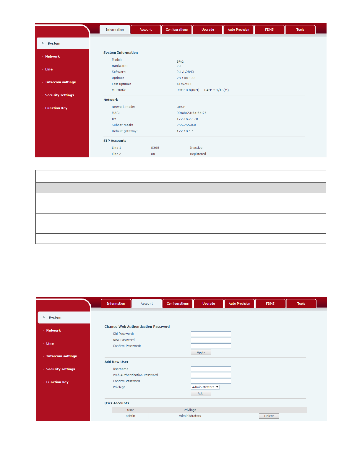
a) Information
Page 10
11
Information
Field Name
Explanation
System
Information
Display equipment model, hardware version, software version, uptime, last uptime and
MEMInfo.
Network
Shows the configuration information of WAN port, including connection mode of WAN
port (Static, DHCP, PPPoE), MAC address, IP address of WAN port.
SIP Accounts
Shows the phone numbers and registration status of the 2 SIP LINES.
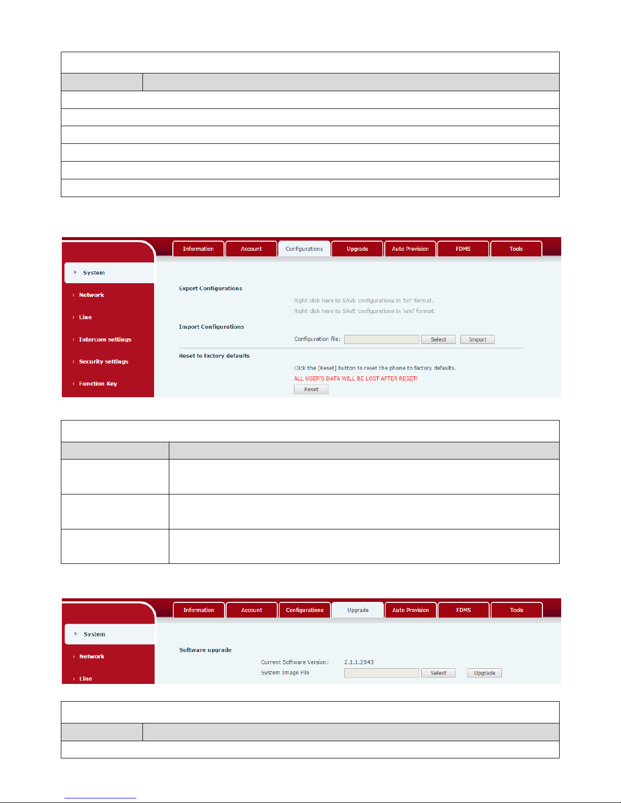
b) Account
Through this page, administrator can add or remove user accounts depend on their needs or modify
existed user accounts permission.
Page 11
12
Account
Field Name
Explanation
Change Web Authentication Password
You can modify the login password of the account
Add New User
You can add new user
User Accounts
Show the existed user accounts’ information
c) Configurations
Configurations
Field Name
Explanation
Export
Configurations
Save the equipment configuration to a txt or xml file. Please right click on the
choice and then choose “Save Link As.”
Import
Configurations
Find the config file, and press Update to load it to the equipment.
Reset to factory
defaults
SPA2 would restore to factory default configuration and remove all configuration
information.
d) Upgrade
Upgrade
Field Name
Explanation
Software upgrade
Page 12

13
Find the firmware, and press Update to load it to the equipment.
e) Auto Provision
Auto Provision
Field Name
Explanation
Common Settings
Current
Configuration
Version
Show the current config file’s version. If the config file to be downloaded is higher
than current version, the configuration would be upgraded. If the endpoints
confirm the configuration by the Digest method, the configuration would not be
upgraded unless it differs from the current configuration
General
Configuration
Version
Show the common config file’s version. If the configuration to be downloaded and
this configuration is the same, the auto provision would stop. If the endpoints
confirm the configuration by the Digest method, the configuration would not be
upgraded unless it differs from the current configuration.
CPE Serial Number
Serial number of the equipment
Authentication
Name
Username for configuration server. It is used for FTP/HTTP/HTTPS. If this is blank,
the phone would use anonymous access
Authentication
Password
Password for configuration server. It is used for FTP/HTTP/HTTPS.
Configuration File
Encryption Key
Encryption key for the configuration file
General
Configuration File
Encryption Key
Encryption key for common configuration file
Save Auto Provision
Information
Save the auto provision username and password in the phone until the server url
changed
DHCP Option
Option Value
The equipment supports configuration from Option 43, Option 66, or a Custom
DHCP option. It may also be disabled.
Page 13

14
Custom Option
Value
Custom option number. It must be from 128 to 254.
SIP Plug and Play (PnP)
Enable SIP PnP
If it is enabled, the equipment would send SIP SUBSCRIBE messages to the server
address when it boots up. Any SIP server compatible with that message would
reply with a SIP NOTIFY message containing the Auto Provisioning Server URL
where the phones can request their configuration.
Server Address
PnP Server Address
Server Port
PnP Server Port
Transportation
Protocol
PnP Transfer protocol – UDP or TCP
Update Interval
Interval time for querying PnP server. Default is 1 hour.
Static Provisioning Server
Server Address
Set FTP/TFTP/HTTP server IP address for auto update. The address can be an IP
address or domain name with subdirectory.
Configuration File
Name
Specify configuration file name. The equipment would use its MAC ID as the
config file name if this is blank.
Protocol Type
Specify the Protocol type FTP, TFTP or HTTP.
Update Interval
Specify the update interval time. Default is 1 hour.
Update Mode
1. Disable – not to update
2. Update after reboot – update only after reboot.
3. Update at time period – update at periodic update period
TR069
Enable TR069
Enable/Disable TR069 configuration
ACS Server Type
Select Common or CTC ACS Server Type.
ACS Server URL
ACS Server URL.
ACS User
User name of ACS.
ACS Password
ACS Password.
TR069 Auto Login
Enable/Disable TR069 Auto Login.
INFORM Sending
Period
Time between transmissions of “Inform”; the unit is second.
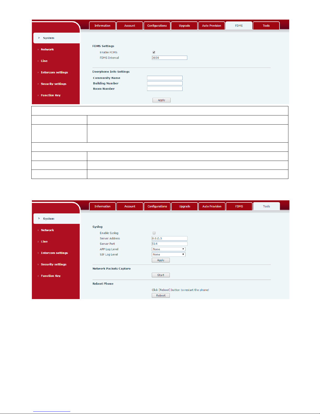
f) FDMS
Page 14
15
FDMS Settings
Enable FDMS
Enable/Disable FDMS configuration
FDMS Interval
The time to send sip Subscribe information to the FDMS server on a regular basis.
Unit seconds
Doorphone Info Settings
Community Name
The name of the community where the device is installed
Building Number
The name of the building where the equipment is installed
Room Number
The name of the room where the equipment is installed
g) Tools
Syslog is a protocol used to record log messages using a client/server mechanism. The Syslog server
receives the messages from clients and classifies them based on priority and type. Then these messages
would be written into a log by rules which the administrator has configured.
There are 8 levels of debug information.
Level 0: emergency; System is unusable. This is the highest debug info level.
Level 1: alert; Action must be taken immediately.
Level 2: critical; System is probably working incorrectly.
Level 3: error; System may not work correctly.
Level 4: warning; System may work correctly but needs attention.
Level 5: notice; It is normal but significant condition.
Page 15
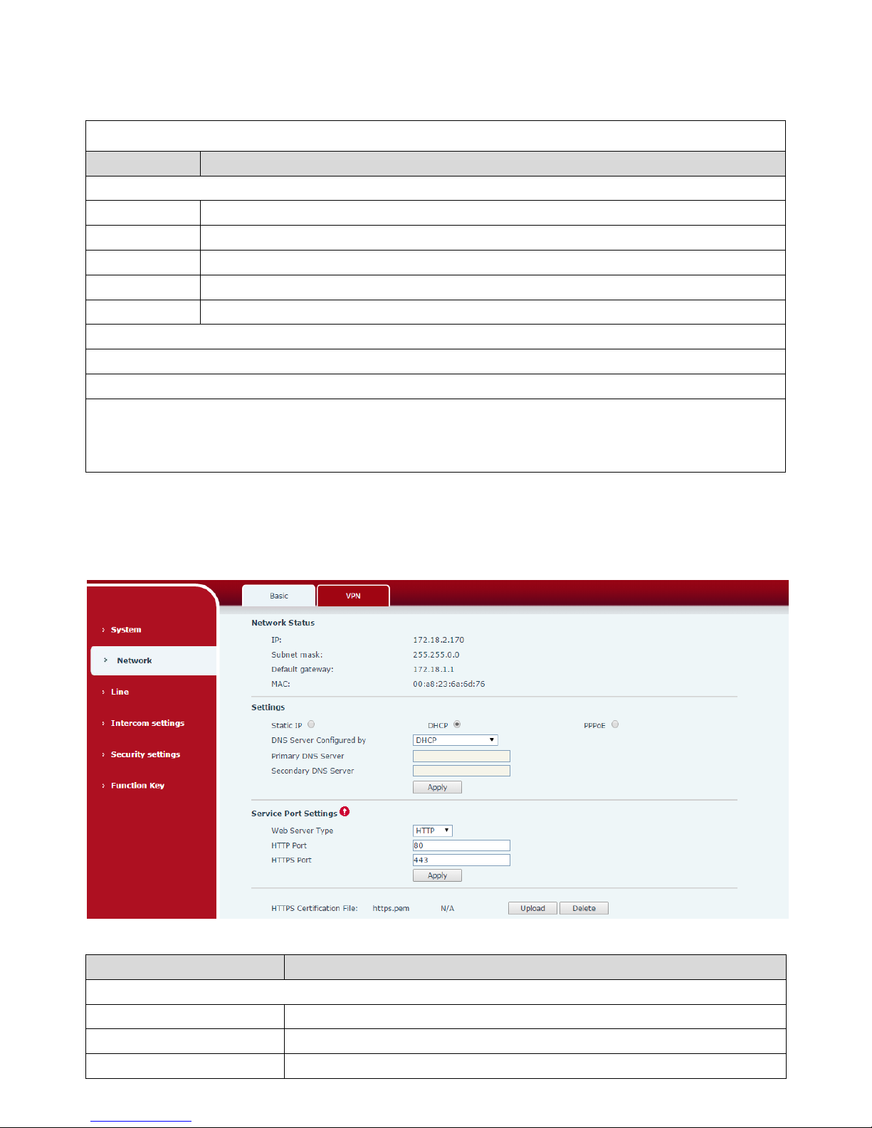
16
Level 6: Informational; It is normal daily messages.
Level 7: debug; Debug messages normally used by system designer. This level can only be displayed
via telnet.
Tools
Field Name
Explanation
Syslog
Enable Syslog
Enable or disable system log.
Server Address
System log server IP address.
Server Port
System log server port.
APP Log Level
Set the level of APP log.
SIP Log Level
Set the level of SIP log.
Network Packets Capture
Capture a packet stream from the equipment. This is normally used to troubleshoot problems.
Reboot Phone
Some configuration modifications require a reboot to become effective. Clicking the Reboot button
would lead to reboot immediately.
Note: Be sure to save the configuration before rebooting.
(2) Network
a) Basic
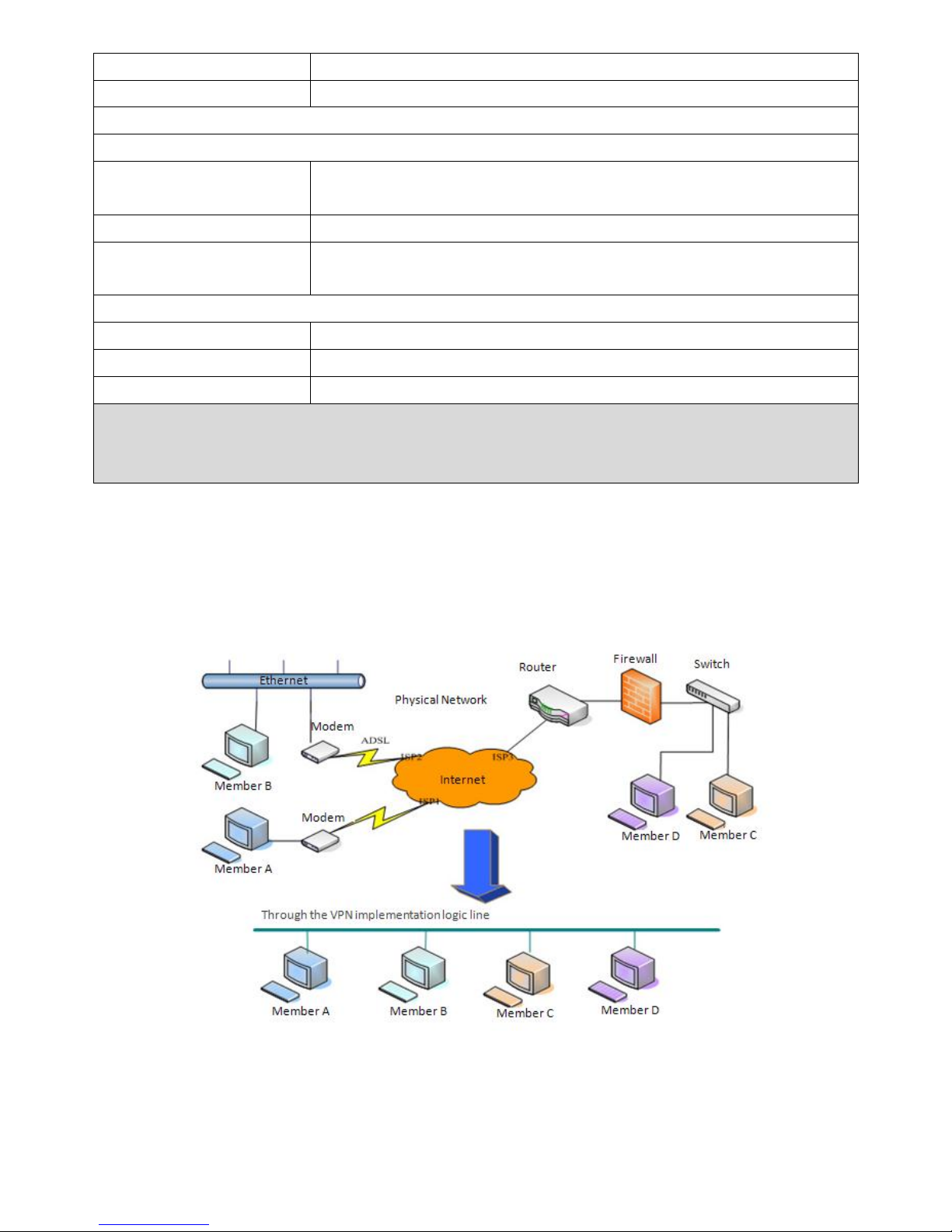
Field Name
Explanation
Network Status
IP
The current IP address of the equipment
Subnet mask
The current Subnet Mask
Default gateway
The current Gateway IP address
Page 16
17
MAC
The MAC address of the equipment
MAC Timestamp
Get the MAC address’s time.
Settings
Select the appropriate network mode. The equipment supports three network modes:
Static IP
Network parameters must be entered manually and would not change. All
parameters are provided by the ISP.
DHCP
Network parameters are provided automatically by a DHCP server.
PPPoE
Account and Password must be input manually. These are provided by
your ISP.
If Static IP is chosen, the screen below would appear. Enter values provided by the ISP.
DNS Server Configured by
Select the Configured mode of the DNS Server.
Primary DNS Server
Enter the server address of the Primary DNS.
Secondary DNS Server
Enter the server address of the Secondary DNS.
After entering the new settings, click the Apply button. The equipment would save the new settings and
apply them. If a new IP address was entered for the equipment, it must be used to login to the phone
after clicking the Apply button.
b) VPN
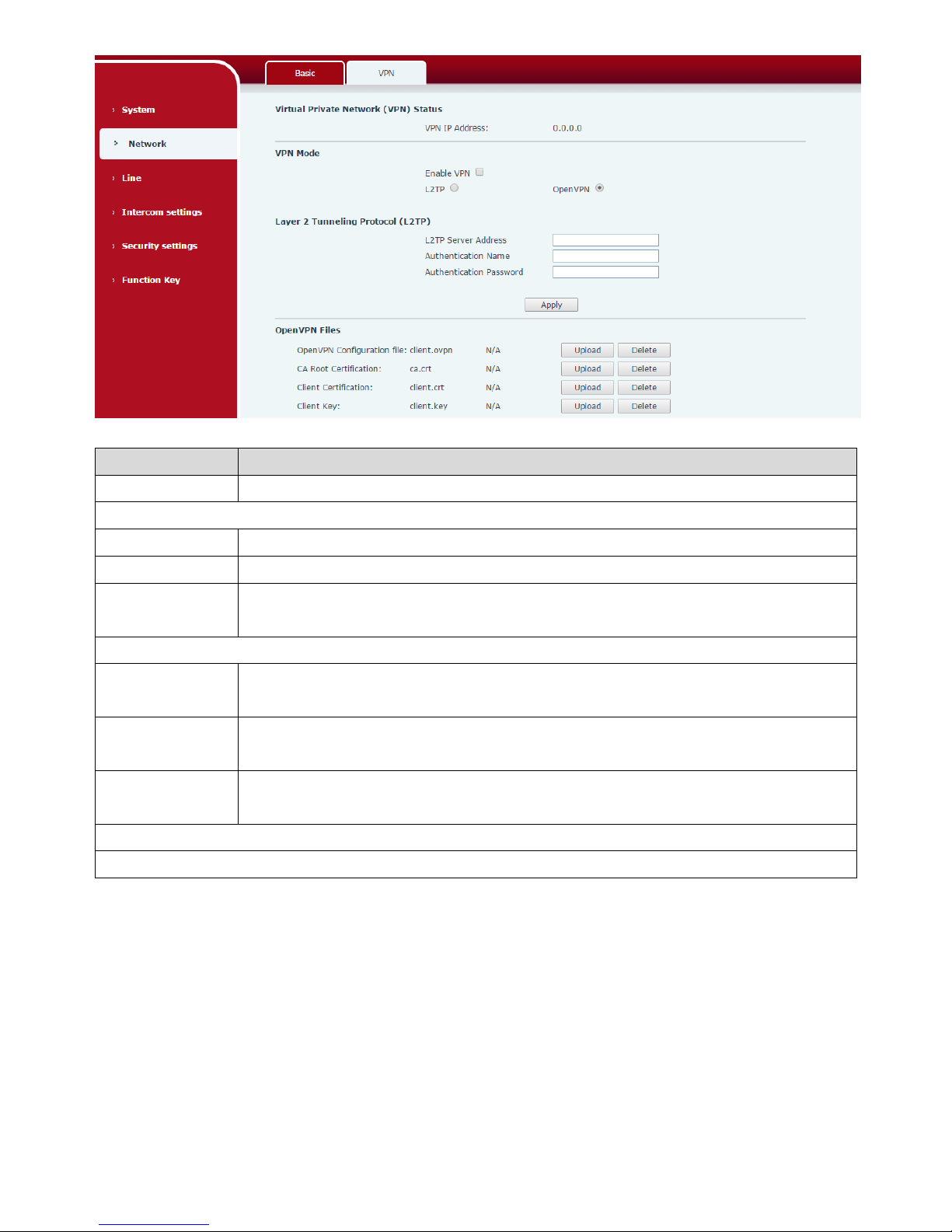
The device supports remote connection via VPN. It supports both Layer 2 Tunneling Protocol (L2TP)
and OpenVPN protocol. This allows users at remote locations on the public network to make secure
connections to local networks.
Page 17
18
Field Name
Explanation
VPN IP Address
Shows the current VPN IP address.
VPN Mode
Enable VPN
Enable/Disable VPN.
L2TP
Select Layer 2 Tunneling Protocol
OpenVPN
Select OpenVPN Protocol. (Only one protocol may be activated. After the selection
is made, the configuration should be saved, and the phone be rebooted.)
Layer 2 Tunneling Protocol (L2TP)
L2TP Server
Address
Set VPN L2TP Server IP address.
Authentication
Name
Set User Name access to VPN L2TP Server.
Authentication
Password
Set Password access to VPN L2TP Server.
Open VPN Files
Upload or delete Open VPN Certification Files
(3) Line
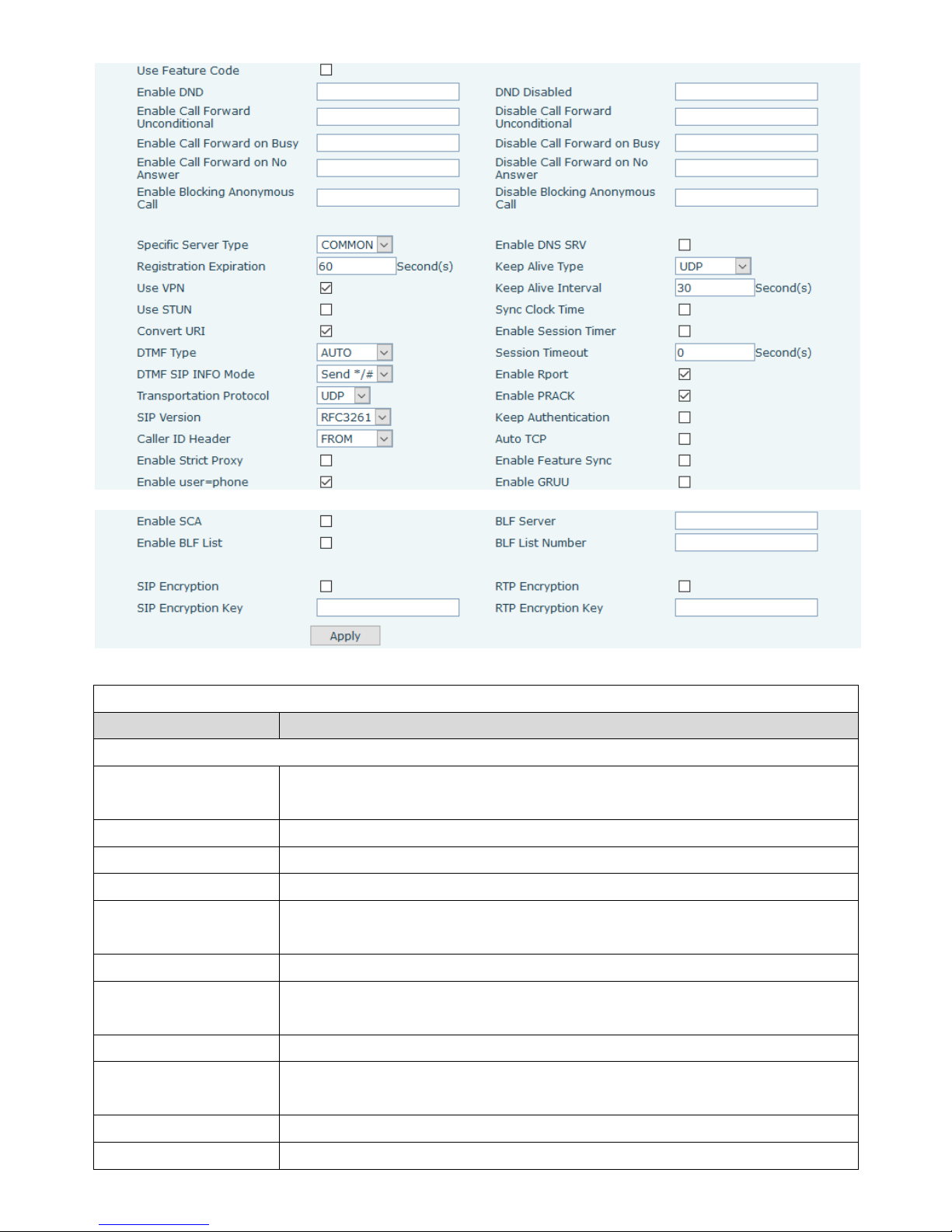
a) SIP
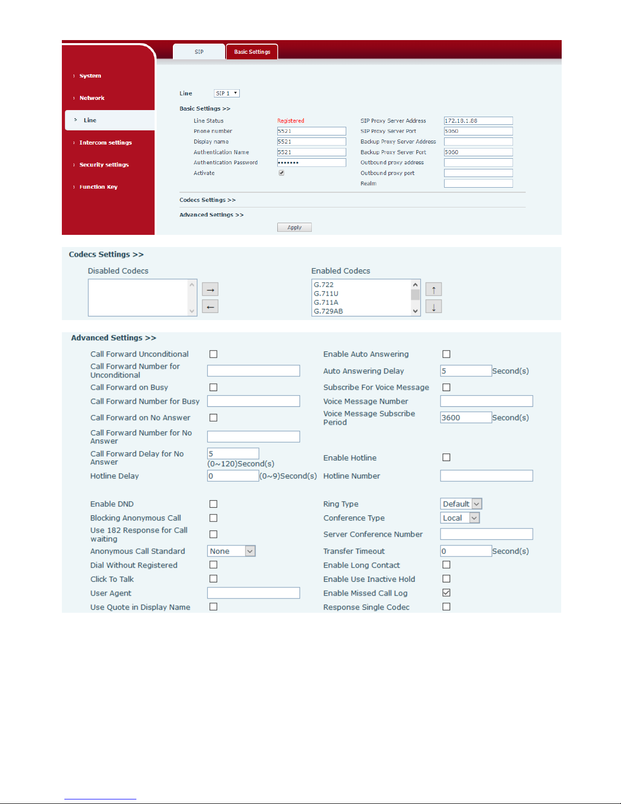
You can configure a SIP server on this page.
Page 18
19
Page 19
20
SIP
Field Name
Explanation
Basic Settings (Choose the SIP line to configured)
Line Status
Display the current line status after page loading. To get the up to date line
status, user must refresh the page manually.
Username
Enter the username of the service account.
Display name
Enter the display name to be sent in a call request.
Authentication Name
Enter the authentication name of the service account
Authentication
Password
Enter the authentication password of the service account
Activate
Whether the service of the line should be activated
SIP Proxy Server
Address
Enter the IP or FQDN address of the SIP proxy server
SIP Proxy Server Port
Enter the SIP proxy server port, default is 5060
Outbound proxy
address
Enter the IP or FQDN address of outbound proxy server provided by the
service provider
Outbound proxy port
Enter the outbound proxy port, default is 5060
Realm
Enter the SIP domain if it is needed by the service provider
Page 20

21
Codecs Settings
Set the priority and availability of the codecs by adding or removing them from the list.
Advanced Settings
Call Forward
Unconditional
Enable unconditional call forwarding, all incoming calls would be forwarded to
the number specified in the next field
Call Forward Number
for Unconditional
Set the number of unconditional call forwarding
Call Forward on Busy
Enable call forward on busy, when the phone is busy, any incoming call would
be forwarded to the number specified in the next field
Call Forward Number
for Busy
Set the number of call forwarding when the SPA2 is busy
Call Forward on No
Answer
Enable call forward on no answer, when an incoming call is not answered
within the configured delay time, the call would be forwarded to the number
specified in the next field
Call Forward Number
for No Answer
Set the number of call forward on no answer
Call Forward Delay for
No Answer
Set the delay time of not answered call before being forwarded
Hotline Delay
Set the delay for hotline before the system automatically dial it
Enable Auto Answering
Enable auto-answering, the incoming calls would be answered automatically
after the delay time
Auto Answering Delay
Set the delay for incoming call before the system automatically answered
answer it
Subscribe For Voice
Message
Enable the device to subscribe a voice message waiting notification, if you
enable it , the device would receive notification from the server if there is
voice message waiting on the server
Voice Message Number
Set the number for retrieving voice message
Voice Message
Subscribe Period
Set the period of voice message notification subscription
Enable Hotline
Enable hotline configuration, the device would dial to the specific number
immediately at audio channel opened by off-hook or turning on hands-free
speaker or headphone
Hotline Number
Set the hotline dialing number
Enable DND
Enable Do-not-disturb, any incoming call on this line would be rejected
automatically
Blocking Anonymous
Call
Reject any incoming call without presenting caller ID
Use 182 Response for
Call waiting
Set the device to use 182 response code at call waiting response
Anonymous Call
Standard
Set the standard to be used for anonymous call
Dial Without Registered
Set call out by proxy without registration
Page 21

22
Click To Talk
Set Click To Talk
User Agent
Set the user agent, the default is Model with Software Version.
Use Quote in Display
Name
Whether to add quote in display name
Ring Type
Set the ring tone type for the line
Conference Type
Set the type of call conference, Local=set up call conference by the device
itself; SPA2 maximally supports two remote parties, Server=set up call
conference by dialing to a conference room on the server
Server Conference
Number
Set the conference room number when conference type is set be Server
Transfer Timeout
Set the timeout of call transfer process
Enable Long Contact
Allow more parameters in contact field per RFC 3840
Enable Missed Call Log
If it is enabled, the phone would save missed calls into the call history record.
Response Single Codec
If it is enabled, the device would use single codec in response to an incoming
call request
Use Feature Code
When this setting is enabled, the features in this section would not be handled
by the device itself but by the server instead. In order to control the
authorization of the features, the device would send feature code to the server
by dialing the number specified in each feature code field.
Specific Server Type
Set the line to collaborate with specific server type
Registration Expiration
Set the SIP expiration period
Use VPN
Set the line to use VPN restrict route
Use STUN
Set the line to use STUN for NAT traversal
Convert URI
Convert not digit and alphabet characters to %hh hex code
DTMF Type
Set the DTMF type to be used for the line
DTMF SIP INFO Mode
Set the SIP INFO mode to send ‘*’ and ‘#’ or ‘10’ and ‘11’
Transportation Protocol
Set the line to use TCP or UDP for SIP transmission
SIP Version
Set the SIP version
Caller ID Header
Set the Caller ID Header
Enable Strict Proxy
Enables the use of strict routing. When the phone receives packets from the
server, it would use the source IP address, not the address in via field.
Enable user=phone
Sets user=phone in SIP messages.
Enable SCA
Enable/Disable SCA (Shared Call Appearance )
Enable BLF List
Enable/Disable BLF List
Enable DNS SRV
Set the line to use DNS SRV which would resolve the FQDN in proxy server into
a service list
Keep Alive Type
Set the line to use dummy UDP or SIP OPTION packet to keep NAT pinhole
opened
Keep Alive Interval
Set the keep alive packet transmitting interval
Enable Session Timer
Set the line to enable call ending by session timer refreshment. The call session
would be ended if there is not new session timer event updating received after
Page 22
23
the timeout period
Session Timeout
Set the session timer timeout period
Enable Rport
Set the line to add Rport in SIP headers
Enable PRACK
Set the line to support PRACK SIP message
Keep Authentication
Keep the authentication parameters of previous authentication
Auto TCP
Using TCP protocol to guarantee usability of transport when SIP messages
have more than 1500 bytes
Enable Feature Sync
Feature Sync with server
Enable GRUU
Support Globally Routable User-Agent URI (GRUU)
BLF Server
The registered server would receive the subscription package from ordinary
application of BLF phone.
Please enter the BLF server, if the sever does not support subscription
package, the registered server and subscription server would be separated.
BLF List Number
BLF List allows one BLF key to monitor the status of a group. Multiple BLF lists
are supported.
SIP Encryption
Enable SIP encryption such that SIP transmission would be encrypted
SIP Encryption Key
Set the pass phrase for SIP encryption
RTP Encryption
Enable RTP encryption such that RTP transmission would be encrypted
RTP Encryption Key
Set the pass phrase for RTP encryption
b) Basic Settings
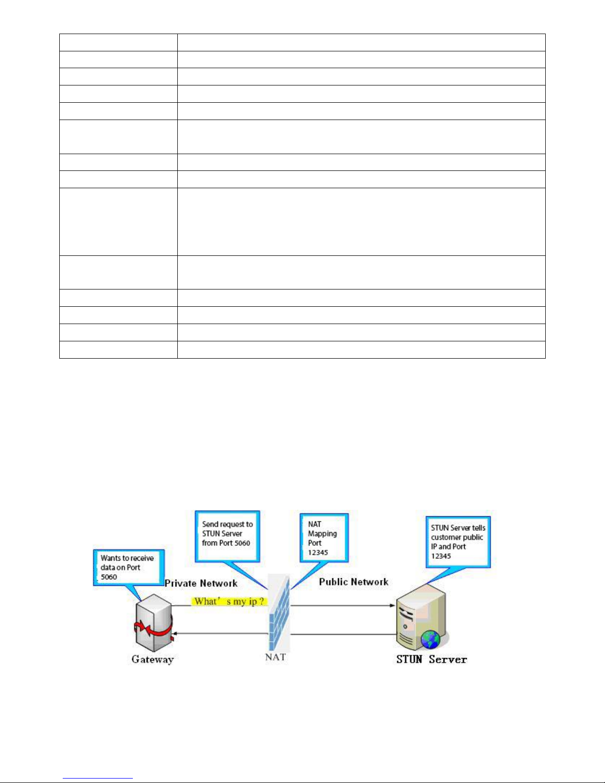
STUN – Simple Traversal of UDP through NAT –A STUN server allows a phone in a private network to
know its public IP and port as well as the type of NAT being used. The equipment can then use this
information to register itself to a SIP server so that it can make and receive calls while in a private
network.
Page 23
24
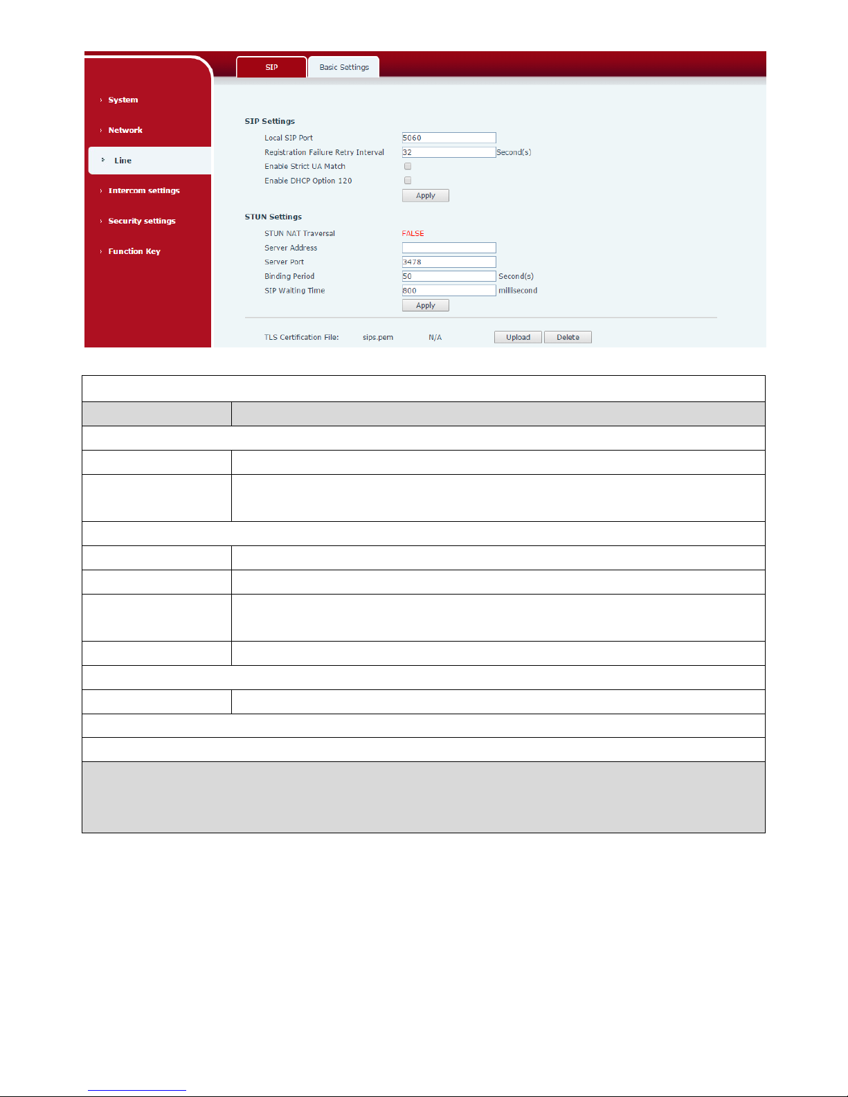
Basic Settings
Field Name
Explanation
SIP Settings
Local SIP Port
Set the local SIP port used to send/receive SIP messages.
Registration Failure
Retry Interval
Set the retry interval of SIP registration when registration failed.
STUN Settings
Server Address
STUN Server IP address
Server Port
STUN Server Port – Default is 3478.
Binding Period
STUN blinding period – STUN packets are sent once every this period to keep the
NAT mapping active.
SIP Waiting Time
Waiting time for SIP. This would vary depending on the network.
SIP Line Using STUN(SIP1 or SIP2)
Use STUN
Enable/Disable STUN on the selected line.
TLS Certification File
Upload or delete the TLS certification file used for encrypting SIP transmission.
Note: the SIP STUN is used to achieve the penetration of SIP NAT; it is a realization of service, when the
equipment is configured the STUN server IP and port (usually the default is 3478), and selected “Use Stun
SIP server”, you can make common SIP equipment achieve penetration.
(4) Intercom settings
a) Features
Page 24
25
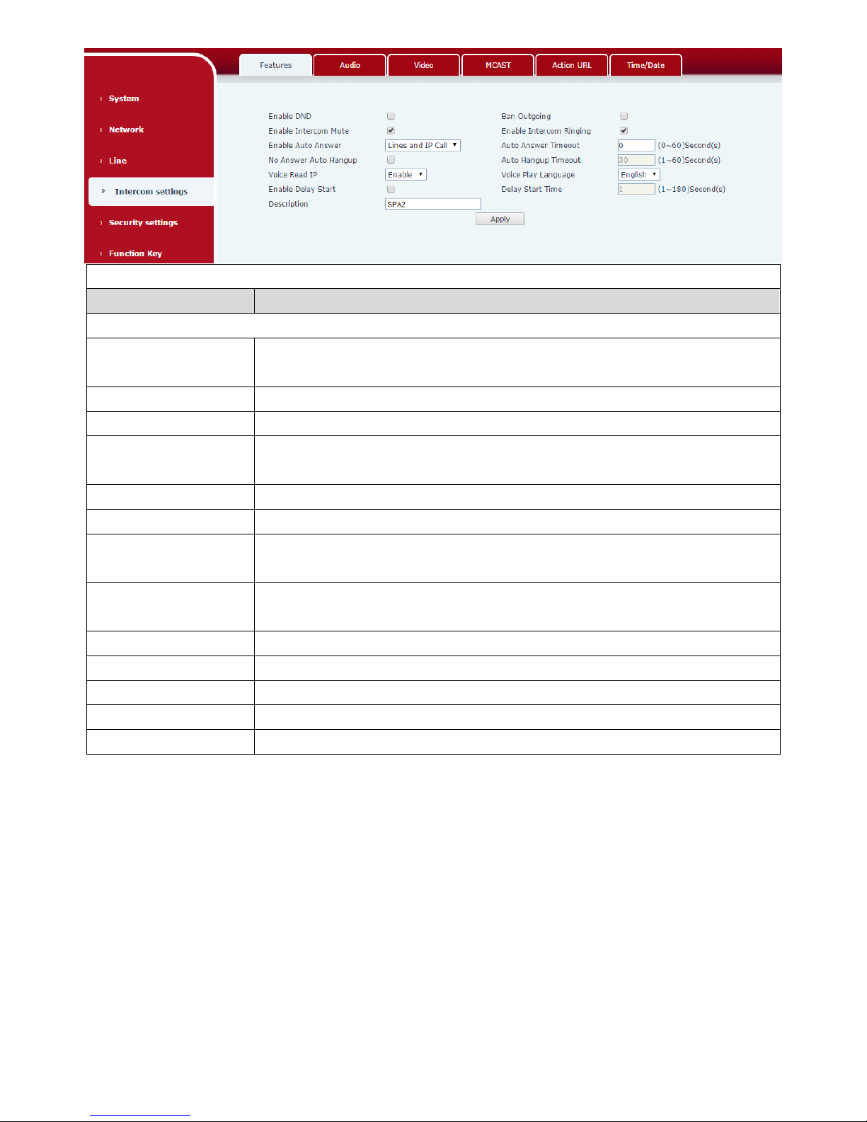
Features
Field Name
Explanation
Basic Settings
Enable DND
DND feature can refuse all incoming calls for all SIP lines, or for individual SIP
line. But the outgoing calls would not be affected
Ban Outgoing
If it is enabled, no outgoing calls can be made.
Enable Intercom Mute
If it is enabled, device would mute incoming calls during an intercom call.
Enable Intercom
Ringing
If it is enabled, device would play intercom ring tone to alert that there is a
new incoming call during an intercom call.
Enable Auto Answer
Enable Auto Answer function
Auto Answer Timeout
Set Auto Answer Timeout
No Answer Auto
Hangup
Enable automatically hang up feature when there is no answer
Auto Hangup Timeout
Configuration in a set time, the device would automatically hang up when
there is no answer
Voice Read IP
Enable or disable voice broadcast IP address
Voice Play Language
Set language of the voice prompt
Enable Delay Start
Enable or disable the start delay
Delay Start Time
Set start delay time
Description
Device description displayed on IP scanning tool software or FDMS.
b) Audio
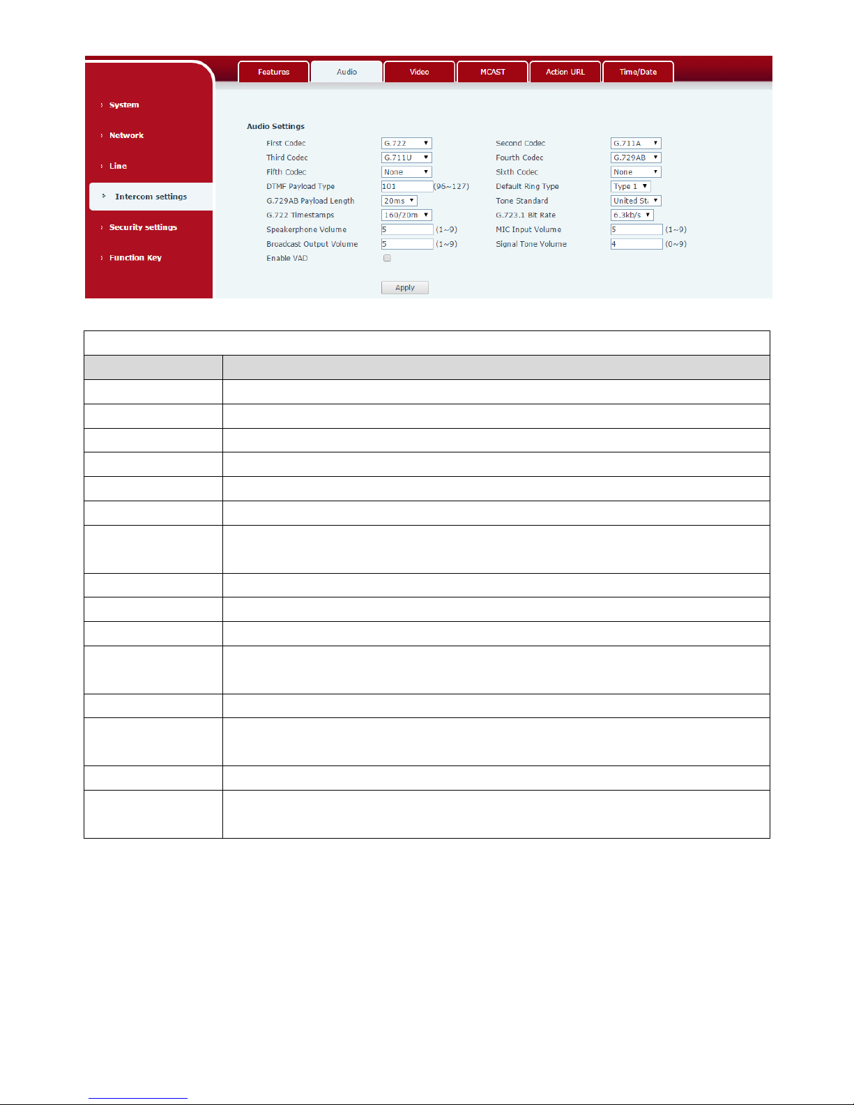
This page configures audio parameters such as voice codec, speak volume, mic volume and ringer
volume.
Page 25
26
Audio Setting
Field Name
Explanation
First Codec
The first codec choice: G.711A/U, G.722, G.723.1, G.726-32, G.729AB
Second Codec
The second codec choice: G.711A/U, G.722, G.723.1, G.726-32, G.729AB, None
Third Codec
The third codec choice: G.711A/U, G.722, G.723.1, G.726-32, G.729AB, None
Fourth Codec
The forth codec choice: G.711A/U, G.722, G.723.1, G.726-32, G.729AB, None
DTMF Payload Type
The RTP Payload type that indicates DTMF. Default is 101
Default Ring Type
Ring sound – there are 9 standard types and 3 user types.
G.729AB Payload
Length
G.729AB Payload length – adjust from 10 – 60 msec.
Tone Standard
Configure tone standard area.
G.722 Timestamps
Choices are 160/20ms or 320/20ms.
G.723.1 Bit Rate
Choices are 5.3kb/s or 6.3kb/s.
Speakerphone
Volume
Set the speaker call volume level.
MIC Input Volume
Set the MIC call volume level.
Broadcast Output
Volume
Set the broadcast output volume level.
Signal Tone Volume
Set the audio signal output volume level.
Enable VAD
Enable or disable Voice Activity Detection (VAD). If VAD is enabled, G729 Payload
length cannot be set greater than 20 msec.
c) Video
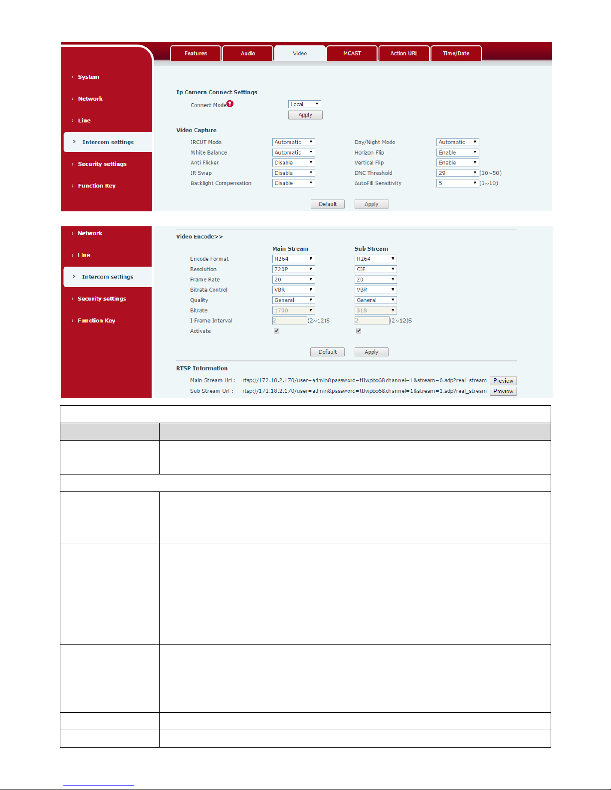
This page allows you to set the video capture and video encode.
Local Mode
Page 26
27
Camera Connect Settings
Field Name
Explanation
Connect Mode
Local: Connect the original camera
External: Connect to another manufacturers camera
Video Capture (Local Mode)
IRCUT Mode
Auto: IRCUT switches according to the actual ambient light level of the camera
Synchronization: The switching of the IRCUT is determined by the actual brightness
of the IR lamp.
Day/Night Mode
Automatic: automatically switches according to the DNC Threshold and the
brightness of the actual environment where the camera is located
Day Mode: The camera's video screen is always colored, if there is IR-cut will be
synchronized to switch.
Night Mode: the camera's video screen is always black and white, if there is IR-cut
will be synchronized switch.
White Balance
Automatic: Automatically adjusts according to the actual environment in which the
camera is located.
Outdoor: installed in the outdoor preferred.
Indoor: installed in the room preferred.
Horizon Flip
The video is flipped horizontally
Anti Flicker
Enable the option. In a fluorescent environment can eliminate the video horizontal
Page 27
28
scroll
Vertical Flip
The video is flipped horizontally
IR Swap
IR-cut filter switch
DNC Threshold
In the Day / Night mode Auto option, the color switching black and white threshold
is set
Backlight
Compensation
In front of a very strong background light can see people or objects clearly
AutoFill Sensitivity
In the environment changes in light and shade, the higher the sensitivity the faster
the video changes
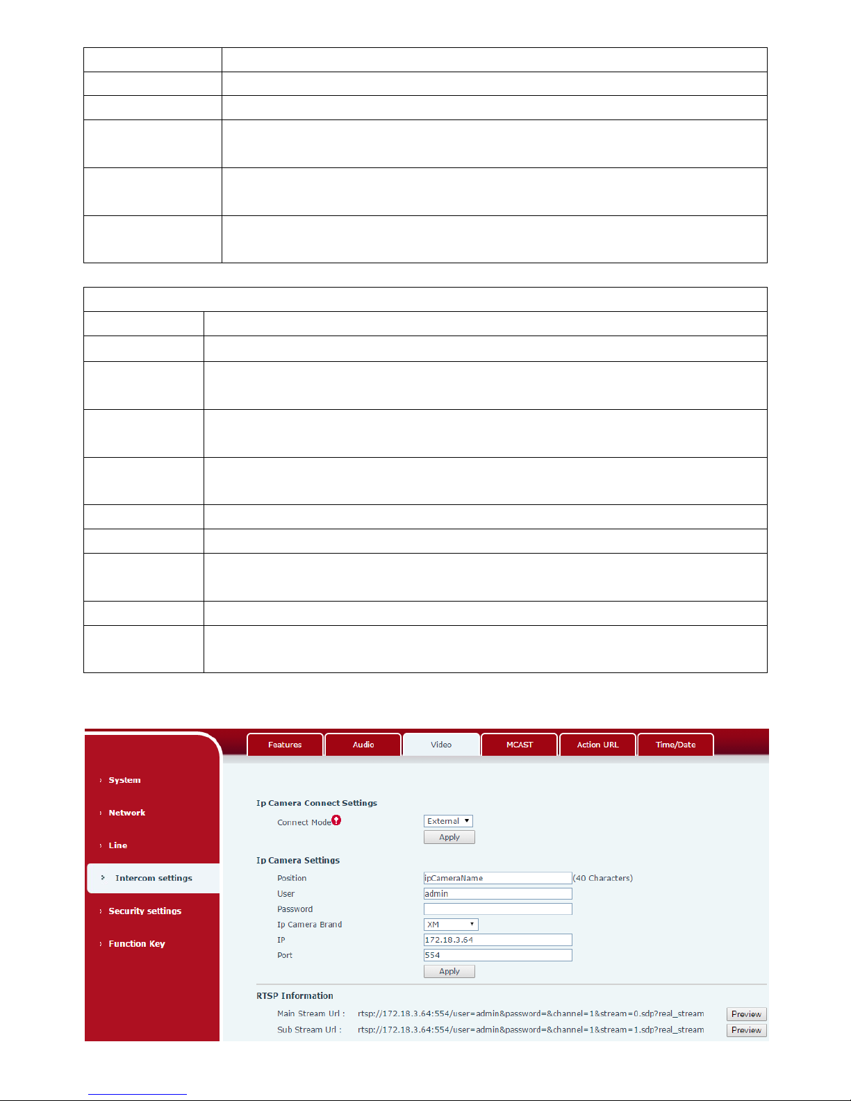
Video Encode(Local Mode)
Field Name
Explanation
Encode Format
Only H.264 encoding format is supported
Resolution
Main stream: support 720P
Sub-stream: you can select CIF (352 * 288), D1 (720 * 576)
Frame Rate
The larger the value is, the more coherent the video would be got; not recommend
adjusted.
Bitrate Control
CBR: If the code rate (bandwidth) is insufficient, it is preferred.
VBR: Image quality is preferred, not recommended.
Quality
Video quality adjustment, the better the quality needs to transfer faster
Bit rate
It is proportional to video file size, not recommend adjusted.
I Frame Interval
The greater the value is, the worse the video quality would be, otherwise the better
video quality would be; not recommend adjusted.
Activate
When you selected it, the stream is enabled, otherwise disabled
Preview
copy and paste the main stream or sub-stream Url into the VLC player, or click
[Preview] to display the current camera video.
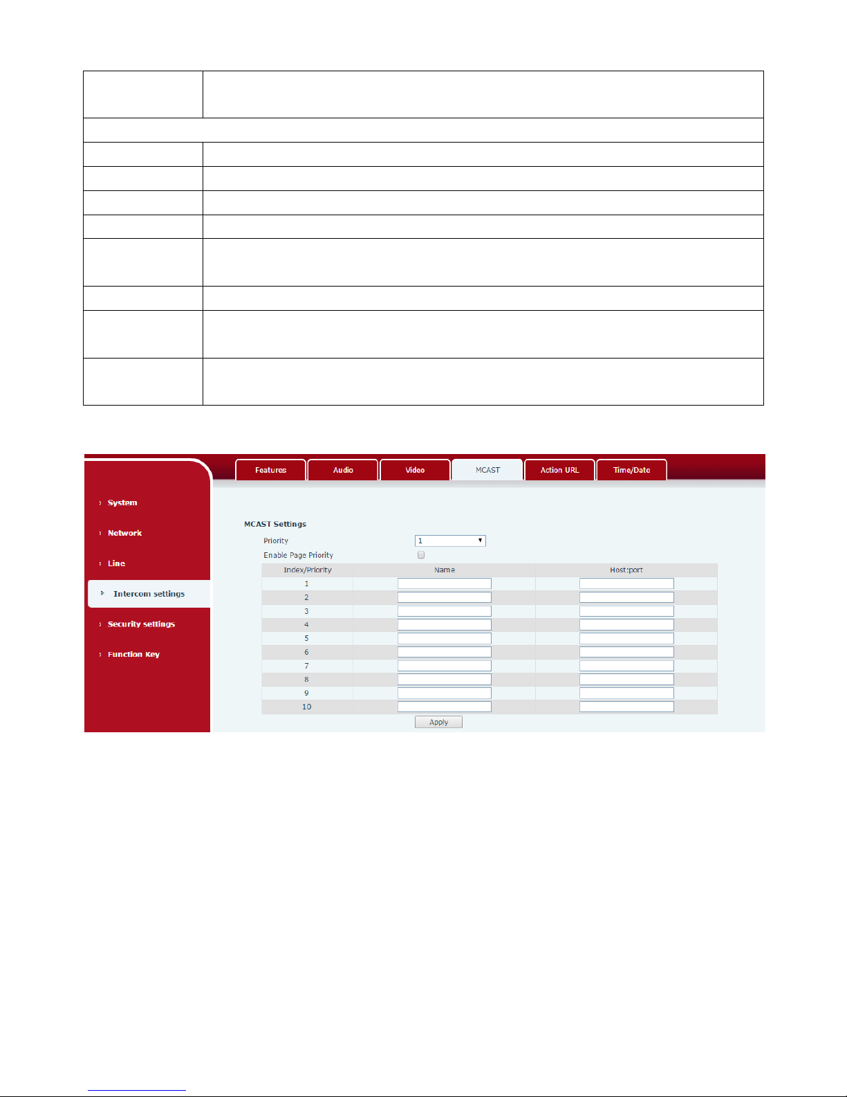
External Mode
Page 28
29
Connection
mode
Select external, click [Apply], restart the device
IP Camera Settings (External Mode)
Field Name
Explanation
User name
External camera login required account
Password
External camera login password required
Camera type
Select the camera manufacturers
IP address
IP address of the camera, please use the camera matching scan tool to obtain the IP
address
Port
Camera port number
RTSP
information
Click [Apply], the connection automatically shows the camera does not show the
reverse
Preview
Copy and paste the main stream or sub-stream Url into the VLC player, or click
[Preview] to display the current camera video
d) MCAST
It is easy and convenient to use multicast function to send notice to each member of the multicast via
setting the multicast key on the device and sending multicast RTP stream to pre-configured multicast
address. By configuring monitoring multicast address on the device, the device monitors and plays the
RTP stream which sent by the multicast address.
MCAST Settings
Equipment can be set up to monitor up to 10 different multicast addresses, used to receive the
multicast RTP stream sent by the multicast address.
Here are the ways to change equipment receiving multicast RTP stream processing mode in the web
interface: set the ordinary priority and enable page priority.
⚫ Priority:
In the drop-down box to choose priority of ordinary calls, if the priority of the incoming streams of
multicast RTP, lower precedence than the current common calls, device would automatically ignore the
Page 29
30
group RTP streams. If the priority of the incoming stream of multicast RTP is higher than the current
common calls priority, device would automatically receive the group RTP streams, and keep the current
common calls in maintained status. You can also choose to disable the function in the receiving threshold
drop-down box, the device would automatically ignore all local network multicast RTP streams.
⚫ The options are as follows:
1-10: To definite the priority of the common calls, 1 is the top level while 10 is the lowest
Disable: ignore all incoming multicast RTP streams
Enable the page priority:
Page priority determines the device how to deal with the new receiving multicast RTP streams
when it is in multicast session currently. When Page priority switch is enabled, the device would
automatically ignore the low priority multicast RTP streams but receive top-level priority multicast
RTP streams and keep the current multicast session in maintained status; If it is not enabled, the
device would automatically ignore all receiving multicast RTP streams.
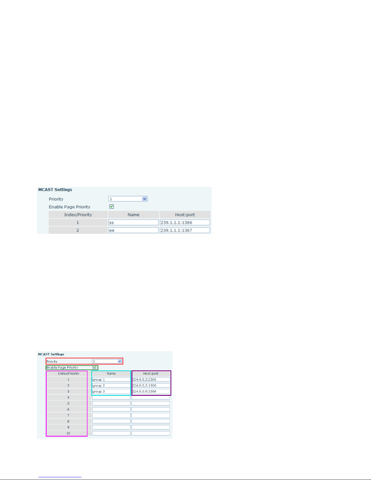
⚫ Web Settings:
The multicast ss priority is higher than that of ee; ss has the highest priority.
Note: when you press the multicast key for multicast session, both multicast sender and receiver
would beep.
Listener configuration
⚫ Blue part (name)
Page 30

31
"Group 1","Group 2" and "Group 3" are your setting monitoring multicast name.The group name
would be displayed on the screen when you answer the multicast. If you have not set, the screen would
display the IP: port directly.
⚫ Purple part (host: port)
It is a set of addresses and ports to listen, separated by a colon.
⚫ Pink part (index / priority)
Multicast is a sign of listening, but also the monitoring multicast priority. The smaller number refers to
higher priority.
⚫ Red part (priority)
It is the general call, non-multicast call priority. The smaller number refers to higher priority. The
followings would explain how to use this option:
The purpose of setting monitoring multicast "Group 1" or "Group 2" or "Group 3" is to launch a
multicast call.
All equipment has one or more common non multicast communication.
When you set the priority as disabled, any level of multicast would not be answered , multicast call is
rejected.
when you set the priority as some value, only the multicast higher than the priority can come in. If you
set the priority as 3, group 2 and group 3 would be rejected, for its priority level is equal to 3 and less
than 3; multicast 1 priority is set up with 2, higher than ordinary call priority, device can answer the
multicast message, at the same time, holding the other call.
⚫ Green part (Enable Page priority)
Set whether to open multicast comparison function, multicast priority is pink part number. Following
explains how to use:
The purpose of setting monitoring multicast "group 1" or “group 3”is listening "group of 1" or “group
3”multicast call of multicast address.
The device has a path or multi-path multicast calls, such as listening to "multicast information group 2".
If multicast is a new "group 1", and because the priority of group 1" is 2, higher than the current call
priority 3 of “group 2”, so multicast call would come in.
If multicast is a new "group 3", and because the priority of group 3" is 4, lower than the current call
priority 3 of “group 2”, the device would listen to the “group 1” and maintain the "group 2".
Multicast service
⚫ Send: when you configure the item, pressing the corresponding key on the equipment shell,
equipment would directly enter the Talking interface; the premise is to ensure no current multicast
call and three-way conference, so the multicast can be established.
⚫ Monitor: IP port and priority are configured to monitor the device, when the call is initiated by
multicast and the call is successful; the device would directly enter the Talking interface.
Page 31
32
e) Action URL
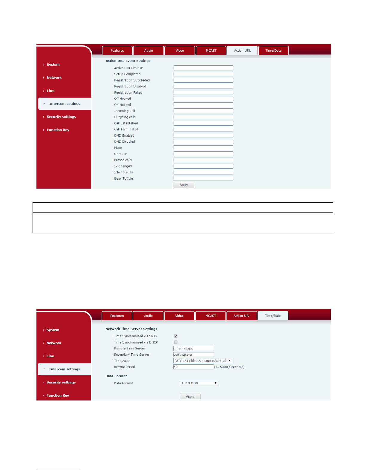
Action URL Event Settings
URL for various actions performed by the phone. These actions are recorded and sent as xml files to the
server. Sample format is http://InternalServer /FileName.xml
f) Time/Date
Page 32
33
Time/Date
Field Name
Explanation
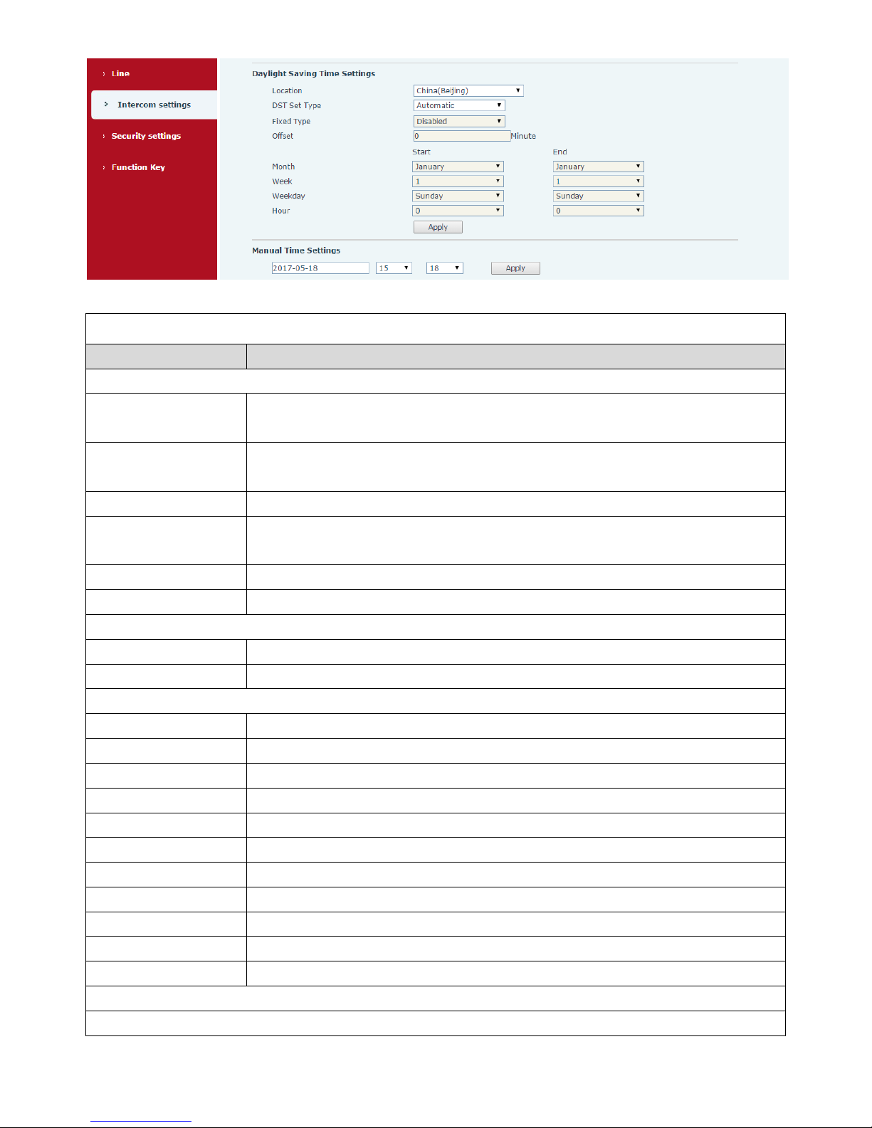
Network Time Server Settings
Time Synchronized via
SNTP
Enable time-sync through SNTP protocol
Time Synchronized via
DHCP
Enable time-sync through DHCP protocol
Primary Time Server
Set primary time server address
Secondary Time
Server
Set secondary time server address, when primary server is not reachable, the device would
try to connect to secondary time server to get time synchronization.
Time zone
Select the time zone
Resync Period
Time of re-synchronization with time server
Date Format
12-hour clock
Set the time display in 12-hour mode
Date Format
Select the time/date display format
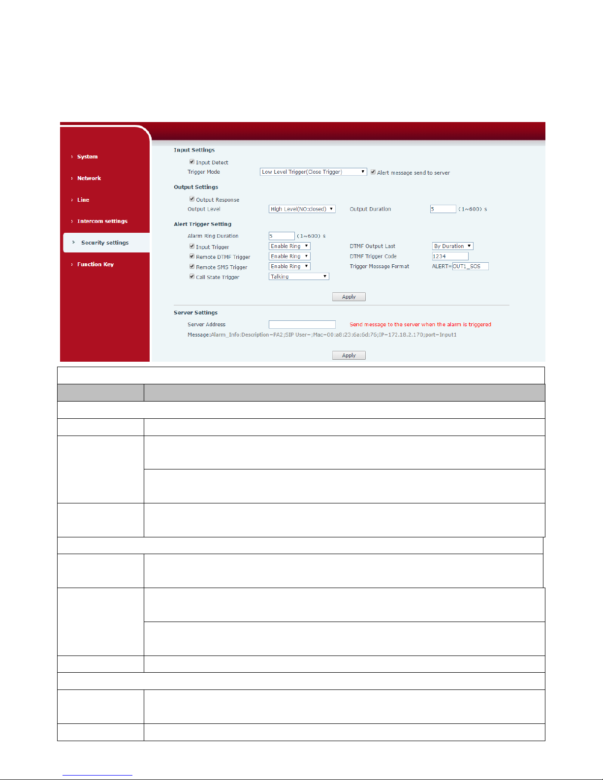
Daylight Saving Time Settings
Location
Select the user's time zone according to specific area
DST Set Type
Select automatic DST according to the preset rules of DST, or you can manually input rules
Offset
The DST offset time
Month Start
The DST start month
Week Start
The DST start week
Weekday Start
The DST start weekday
Hour Start
The DST start hour
Month End
The DST end month
Week End
The DST end week
Weekday End
The DST end weekday
Hour End
The DST end hour
Manual Time Settings
The time might be set manually, needed user to disable SNTP service first.
Page 33
34
(5) Security settings
Security Settings
Field Name
Field Name
Input settings
Input Detect
Enable or disable Input Detect
Trigger Mode
When choosing the low level trigger (Closed Trigger), detect the input port (low level)
closed trigger.
When choosing the high level trigger (Disconnected Trigger), detect the input port
(high level) disconnected trigger.
Alert message
send to server
Enable or disable Input port send message to server
Output Settings
Output
Response
Enable or disable Output Response
Output Level
When choosing the low level (NO: open), when meet the trigger condition, trigger the
NO port disconnected.
When choosing the high level (NO: closed), when meet the trigger condition, trigger
the NO port close.
Output Duration
The port changes the duration. The default is 5 seconds.
Alert Trigger Setting
Alarm Ring
Duration
duration of alarm ring
Input Trigger
When the input port meet to trigger condition, the output port will trigger (The Port
Page 34
35
level time change, By < Output Duration > control).
You can choose to enable or disable the ringtone
DTMF Output
Last
By duration
The Port level time change, By < Output Duration > control
By Calling State
By call state control, after the end of the call, port to return the
default state
Remote DTMF
Trigger
Received the terminal equipment to send the DTMF password, if correct, which
triggers the corresponding output port.
You can choose to enable or disable the ringtone
DTMF Trigger
Code
During the call, receive the terminal equipment to send the DTMF password, if correct,
which triggers the corresponding output port. The default is 1234.
Remote SMS
Trigger
Enable or disable Remote SMS Trigger.
You can choose to enable or disable the ringtone
Trigger Message
Format
In the remote device or server to send instructions to ALERT=[instructions], if correct,
which triggers the corresponding output port
Call State Trigger
The port output continuous time synchronization and trigger state changes, including
the trigger conditions. Four models, such as: call trigger output port, will be in a call
state to continue to respond)
1, Taking;
2, Taking and ringing;
3, ringing;
4, Call.
Server Settings
Server Address
Configure remote response server address (including remote response server address
and tamper alarm server address). When the input port is triggered will send a short
message to the server, the message format is as follows: Alarm Info: Description=SPA2;
SIP User=;Mac=00:a8:34:68:23:d1;IP=172.18.2.243;port=Input1
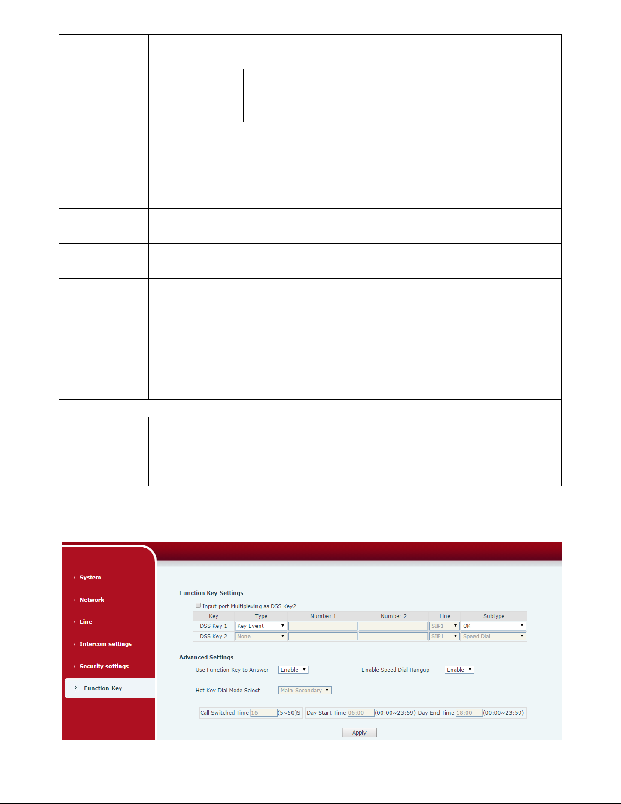
(6) Function Key
a) Function Key Settings
Page 35
36
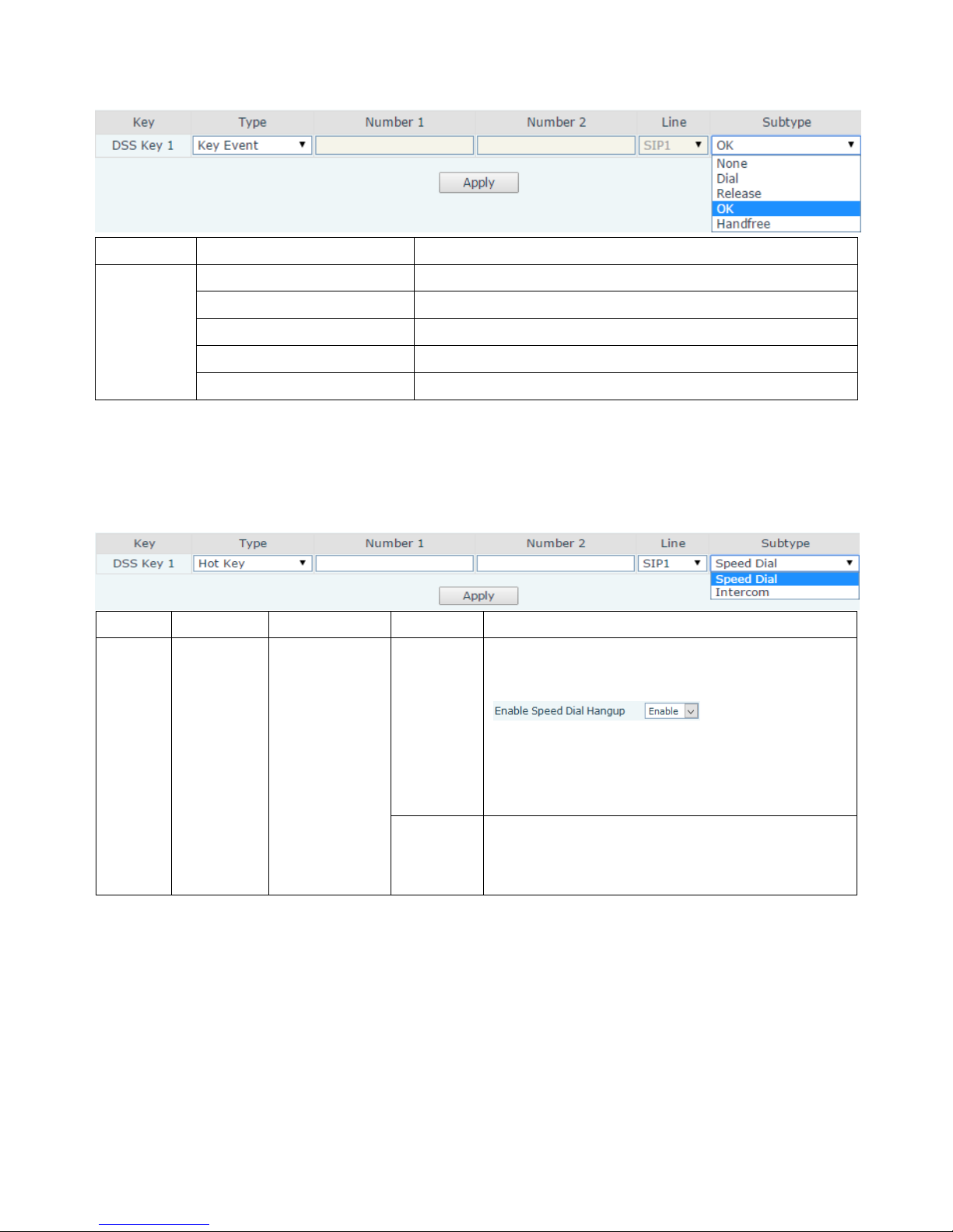
➢ Key Event
You might set up the key type with the Key Event.
Type
Subtype
Usage
Key Event
None
No responding
Dial
Dialing function
Release
Delete password input, cancel dialing input and end call
OK
identification key
Handfree
The hand-free key (with hooking dial, hanging up functions)
➢ Hot Key
You might enter the phone number in the input box. When you press the shortcut key, equipment
would dial preset telephone number. This button can also be used to set the IP address: you can press the
shortcut key to directly make a IP call.
Type
Number
Line
Subtype
Usage
Hot Key
Fill the
called
party’s SIP
account or
IP address
The SIP
account
corresponding
lines
Speed Dial
Using Speed Dial mode together with
, can define whether
this call is allowed to be hung up by re-pressing
the speed dial key.
Intercom
In Intercom mode, if the caller’s IP phone
supports Intercom feature, the device can
automatically answer the Intercom calls
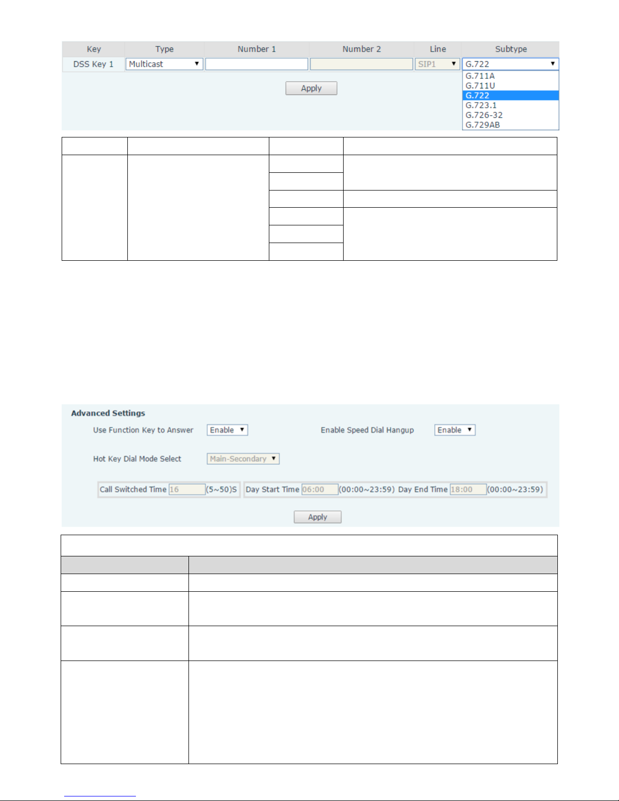
➢ Multicast
Multicast function is to deliver voice streams to configured multicast address; all equipment
monitored the multicast address can receive and play it. Using multicast functionality would make deliver
voice one to many which are in the multicast group simply and conveniently.
The Function Key multicast web configuration for calling party is as follow:
Page 36
37
Type
Number
Subtype
Usage
Multicast
Set the host IP address and
port number; they must be
separated by a colon
G.711A
Narrowband speech coding (4Khz)
G.711U
G.722
Wideband speech coding (7Khz)
G.723.1
Narrowband speech coding (4Khz)
G.726-32
G.729AB
◆ operation mechanism
You can define the Function Key configuration with multicast address, port and used codec. The device
can configure via WEB to monitor the multicast address and port. When the device make a multicast, all
devices monitoring the address can receive the multicast data.
◆ calling configuration
If the device is in calls, or it is three-way conference, or initiated multicast communication, the
device would not be able to launch a new multicast call.
b) Advanced Settings
Advanced Settings
Field Name
Field Name
Input Port Multiplexing 2
Enable or disable input port reuse for DSS key 2.
Use Function Key to
Answer
Enable or disable DSS Key answer
Enable Speed Dial key
Hang up
Enable or disable the DSS Key to hang up
Hot Key Dial Mode Select
Number 1 Transfer Call Number 2 Mode Select.
<Primary /Secondary>mode allow system to call primary extension first, if
there is no answer, system would cancel the call and then call secondary
extension automatically.
<Day/Night>mode allow system to check the calling time is belong to day
time or night time, and then system decides to call the number 1 or number
Page 37

38
2 automatically.
Users just press speed dial key once.
Call Switched Time
Set number 1 to transfer call number 2 time, default 16 seconds
Day Start Time
The start time of the day when you select<Day/Night>mode.
Day End Time
The end time of the day when you select <Day/Night>mode.
V. Appendix
1. Technical parameters
Communication protocol
SIP 2.0(RFC-3261)
Main chipset
Broadcom
Speech
flow
Protocols
RTP
Decoding
G.729、G.723、G.711、G.722、G.726
WAN
10/100BASE-TX s Auto-MDIX, RJ-45
MIC(Optional)
electret condenser microphone
Sensitivity: -38dB, bias voltage 2.2V
Speaker(Optional)
4Ω / 3W, internal magnetic horn, diameter: 57mm
Camera(Optional)
1/4 "color CMOS, 1 megapixel, wide angle
Power supply mode
12~24V 2A DC or PoE
PoE
PoE 802.3af (Class 3 - 6.49~12.95W)
Cables
CAT5 or better
Shell Material
Aluminum alloy
Working temperature
-20°C to 60°C
Storage temperature
-40°C to 70°C
Installation way
Embedded or desktop
External size
113x83x28mm
Package size
138x108x77mm
Equipment weight
250g
2. Basic Functions
⚫ 2 SIP lines
⚫ PoE Enabled
⚫ External power supply
⚫ Supports two lines RTSP
Page 38

39
⚫ Voice broadcast IP address
⚫ button or remote volume adjustment
⚫ switch signal input and output
⚫ Talkback recording output
⚫ Default auto answer
⚫ Dynamic multicast function
⚫ Support for Function key interface
⚫ Support monophonic active speakers
 Loading...