

Page 1
1
SIP Industrial Products Limited
Gelders Hall Road
Shepshed
Loughborough
Leicestershire
LE12 9NH
United Kingdom
For help or advice please contact
your distributor, or sip directly on:
Tel.: 01509 500400
Email:
[email protected]
or
www.sip-group.com
Please read and fully understand the instructions in this manual before
operation. Keep this manual safe for future reference.
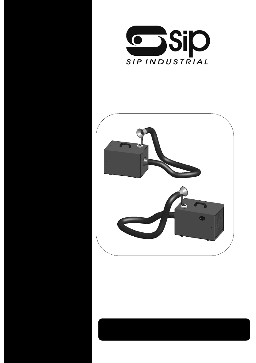
SIP FX100 Welding Fume Extractor
SIP Code 05815
Page 2

2
Page 3
3
INDEX
Page Descripon
4 - 10 Safety Instrucons
10 Guarantee
11 Technical Specicaon
12 Geng To Know Your Fume Extractor
13 Operang Instrucons
14 - 17 Maintenance
18 Wiring Diagram
19 Troubleshoong
20 Parts Informaon
22 UK Declaraon Of Conformity
23 EU Declaraon Of Conformity
Page 4
4
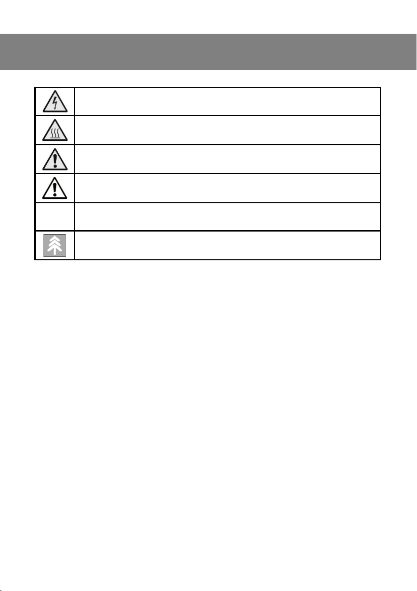
SAFETY SYMBOLS USED THROUGHOUT THIS MANUAL
Danger / Cauon: Risk of electrical injury or damage.
Danger / Cauon: Risk of injury or damage.
Danger / Cauon: Risk of personal injury and / or the possibility of dam-
age.
ATTENTION: draws aenon to situaons and problems associated with
the eciency of the machine that do not aect the safety of people.
!
Note: Supplementary informaon
ENVIRONMENT: draws aenon to behaviors and procedures to limit the
environmental impact related to the use of the machine.
Page 5

5
SAFETY INSTRUCTIONS
• Do not use the machine in places where there is a risk of explosion or re. Do
not approach the machine with naked ames or other.
• Use the machine in a dry environment, not subject to condensaon phenomena of atmospheric humidity and protected from direct exposure to atmospheric agents and sunlight.
• Always use the machine in adequate lighng condions. The environment of
use must be well venlated and in compliance with the regulaons in force on
hygiene and safety at work.
• Do not use the machine in harsh environmental condions: the ambient temperature must be between 5 ° C and 40 ° C, with a humidity level less than
80%.
• Check that the electrical power supply system of the machine is up to standard
and equipped with appropriate protecon devices against current leakage and
short circuit.
• The use of the product must be preceded by adequate sta training and by
reading this User Manual.
• The machine can be used as a portable unit for the extracon, ltraon and
deodorisaon of welding fumes in the electronics industry in general, in
body shop departments and for small welds.
• The use of the machine is allowed only to adult and responsible operators,
properly trained.
• The machine must be handled with cauon, respecng the rules given in this
manual.
• Aer use, do not leave the exible hose unaended on the ground, as it
maybe a trip hazard or get damaged.
• Handle the hose and the cap using protecve gloves in order to avoid burns
due to the high temperatures that can be reached in condions of prolonged
use.
• Do not carry out repairs or modicaons to the machine.
• Do not carry out maintenance when the machine is running. To clean the
machine, do not use corrosive or harmful detergents.
Page 6

6
SAFETY INSTRUCTIONS
• In case of breakdown or malfuncon of the machine DO NOT USE IT AND
CLEARLY LABEL IT AS OUT OF THE SERVICE. Contact our Customer Service for
any repairs.
• Wear suitable personal protecve equipment (PPE) during use, maintenance
and cleaning of the machine.
• During the maintenance phases, do not disperse any residues in the surround-
ing environment, but comply with the current regulaons.
WELDING
• The intended use of the machine is the sucon of welding fumes in industry
and automove workshops: it is forbidden to use it to suck up other sub
stances (dust, liquids, vapors, etc.), especially if ammable, explosive, corro
sive, etc
• The machine must only be used in a work environment protected from at-
mospheric agents.
• The machine must be used with cauon, making sure that the power supply
cable and exible hose are not placed in dangerous areas or where they can
hinder other operators.
• The machine was not designed to be used in a potenally explosive atmosphere: its use in environments where there is a risk of re or explosion is
prohibited.
• The nozzle must allow the entry of air at room temperature in a rao of 1: 1
with the aspirated fumes. This is necessary to lower the average tempera-
ture of the sucked gases, preserving the life of the internal components of
the machine.
• It is forbidden to use it with systems for capturing and conveying the ow
rate that do not allow the entry of air at room temperature as prescribed.
• SIP Industrial Products disclaims any liability for damage to the machine itself, to people or property caused by the incorrect use of the collecon cap
or the use of inappropriate hoods.
Page 7

7
SAFETY INSTRUCTIONS
ELECTRICAL
• ELECTRICAL RISK:
• It is forbidden to perform repairs or maintenance on the machine when it is
connected to the electrical power system; however, should it be necessary
to operate with the machine powered on, this pracce can only be carried
out by Qualied Personnel, with experse in the electrotechnical eld, or by
SIP Industrial Products / SIP Service Agent.
• Adopt all the precauons according to the regulaons in force if you have to
operate with the machine powered on: wear insulang gloves and shoes and
use insulang mats and insulated tools. Also check that the system to which
the machine is connected is protected from leaks and short circuits, as required by current legislaon
• RISK OF FIRE OR EXPLOSION:
• The machine cannot be used in environments with a high risk of re or ex-
plosion. It is forbidden to store, even temporarily, potenally ammable or
deagrang substances in the rooms where the exhaust gas extracon system is installed.
• RISK OF BURNS:
• During work operaons, the machine, especially on the exhaust side, can
reach high temperatures with consequent risk of burns. Use heat-resistant
gloves for handling the machine.
• RISK OF FAILURE OR MALFUNCTIONING:
• Long use of the machine in parcularly severe environmental condions
(brackish environment, excessive temperature, condensaon, presence of
dust, exposure to atmospheric agents, etc.), can cause malfuncons or failures of the product and compromise its safety.
• Respect the requirements indicated in the "Safety Warnings" relang to the
work environment, reported in this User Manual.
• RISK OF INCORRECT INTERPRETATION OF SAFETY LABELS:
• Following the idencaon of the main sources of danger that emerged
from the Risk Analysis, Safety Sckers, with unied symbols, were applied to
the machine to signal these sources of danger. Over me, these sckers can
become illegible or dicult to interpret due to aging or wear.
Page 8
8
• The user is required to immediately replace the Safety Sckers that become
illegible due to aging, wear or damage.
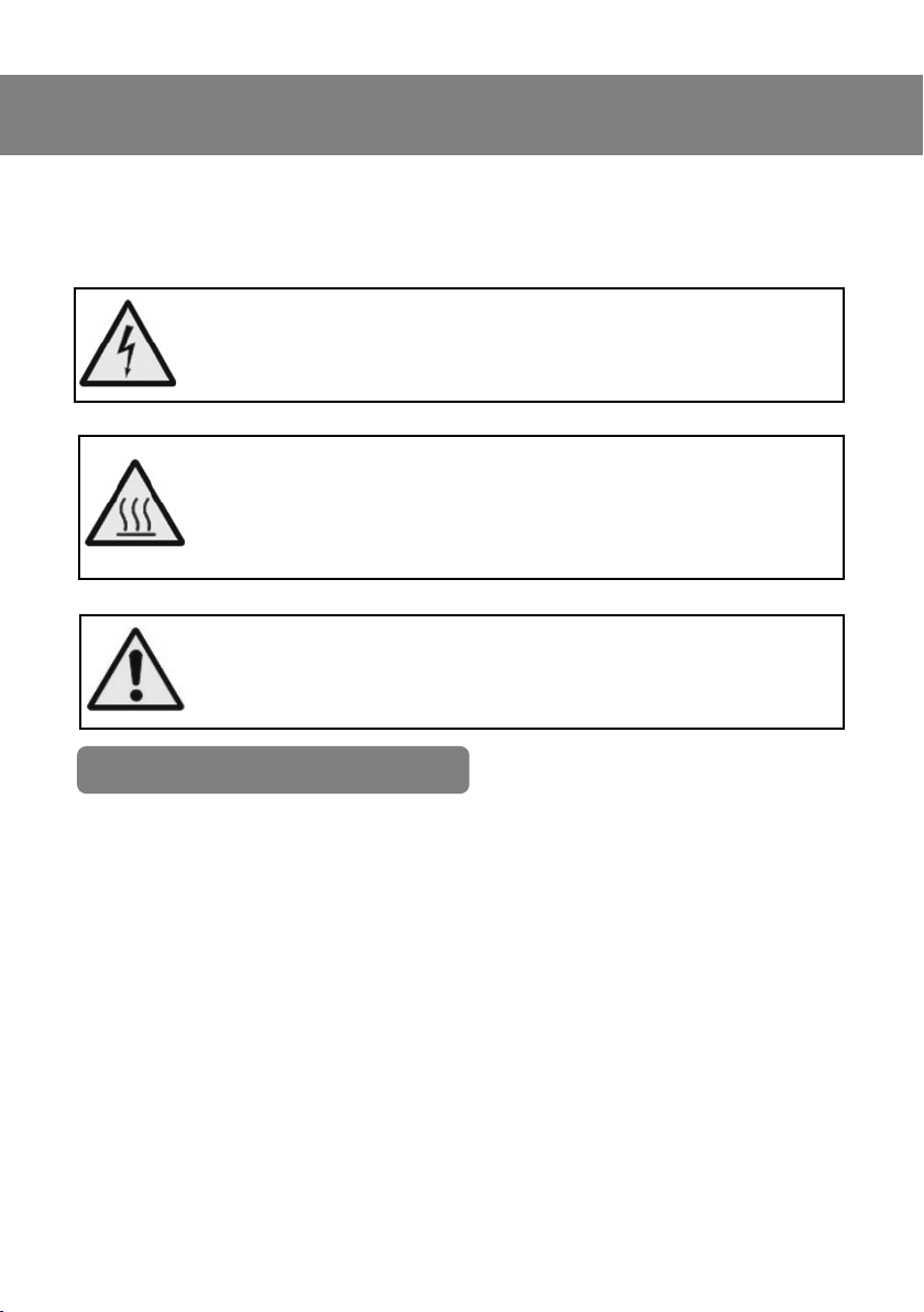
Danger: Risk of Electric Shock. Electrocuon risk around the mains
input and socket. Do not touch electrical parts. Do not exnguish
electrical res using water, use an appropriate exnguisher.
Danger: Risk of Burns from contact with Hot Surfaces.During normal work operaons the machine casing, especially on the exhaust
side, and the acvated carbon lter can reach temperatures above
60 ° C with consequent risk of burns.
Warning: Always use appropriate personal protecve equipment
(PPE) .
• The SIP FX100 machine is accompanied by this User Manual which contains the technical informaon, gures, instrucons and warnings necessary for correct use of the product.
• The User Manual must accompany the machine throughout its life cycle,
even in the event of sale or transfer; must be stored in such a way as to
ensure its integrity and must be easily accessible in case of need (it is
advisable to keep a copy near the machine).
• The purpose of this document is the transmission of the informaon necessary for the competent and safe use of the product and therefore must
be made available to all personnel who work with the machine and its
systems (Plant Manager, User, Maintenance Technician and Qualied
Personnel machine installaon, power supply and commissioning).
• In the event that this manual is lost or damaged, it is recommended to
DOCUMENTATION
SAFETY INSTRUCTIONS SAFETY INSTRUCTIONS
Page 9

9
request a new copy directly from SIP Industrial Products Ltd or our website.
SAFETY INSTRUCTIONS
DELIVERY, TRANSPORT & HANDLING
• Upon delivery, the machine is contained in a single package. Upon receipt of
the goods, check that the packaging integrity and that there are no signs of
possible damage suered during transport; if necessary, before opening the
package, document the problems encountered with some photographs.
• In the event that the product is damaged, do not use and report the incident
to SIP Industrial Products .
• Arrange a place protected from bad weather to store the product waing for
the installaon, in case installaon is not immediate.
• The product cannot be exposed to bad weather, store and use it in a dry and
covered room.
• In case of damage to the product during transport, do not proceed with use
• For the transport operaon, the operator must unload the packaged ma-
chine using a suitable means for liing.
• Remove the packaging only at the me of nal commissioning of the machine and dispose of the materials in accordance with current regulaons.
• The loading and unloading operaons and subsequent handling must be
performed keeping the machine in its original packaging and using an appropriate liing device.
• Make sure that the liing means are suitable for the weight of the machine
and carry out handling in safe condions, in accordance with the provisions
of current legislaon.
• Personnel not involved in the operaon must keep a safe distance. Check
that there are no objects resng on the machine and that the moving parts
have been xed. The oor must be at, clean and free of residues
• When opening the packaging, the operator must check that all machine
components are present and that they have not been damaged during
transport. If not, contact our dealer.
Page 10
10
• Connect the exible sucon hose to the machine's sucon duct and secure it
using the hose clamp supplied.
• Assemble the handle of the machine using the 2 screws supplied and a No. 6
Allen key.
• Do not leave the packaging elements (cellophane, wood, cardboard, etc.)
within the reach of children, as they are potenal sources of danger.
• Do not dispose of the packaging materials in the environment. The packaging
must be done in accordance with the regulaons.
GUARANTEE
SAFETY INSTRUCTIONS
This SIP FX100 welding fume extractor is covered by a 24 month parts and labour
warranty covering failure due to manufacturers defects. .
This does not cover failure due to misuse or operang the extractor outside the
scope of this manual - any claims deemed to be outside the scope of the warranty
may be subject to charges Including, but not limited to parts, labour and carriage
costs.
Failure to regularly clean your extractor will shorten its working life and reduce
performance.
Failure to clean and / or replace the lters regularly will impact the life of the mo-
tor, and excess ingress or damaged caused by ingress to the motor will not be covered under the warranty.
The warranty does not cover consumable items such as hoses, lters etc and also
components subject to normal wear & tear.
NOTE: Proof of purchase will be required before any warranty can
be honoured. .
!
Page 11
11
TECHNICAL SPECIFICATION
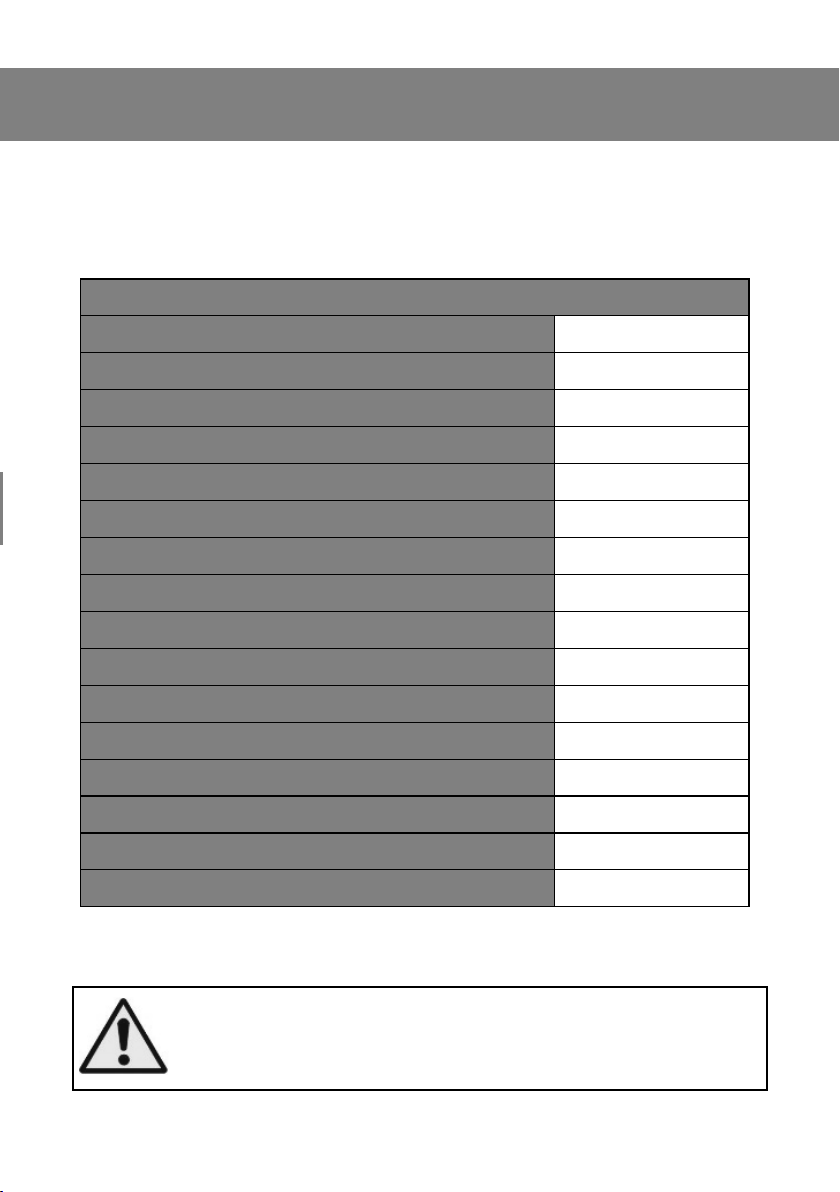
The SIP FX100 machine described in this manual is a portable unit for the extracon, ltraon and deodorisaon of welding fumes in industry, automove workshops and for small welding fabricators.
05815 SIP FX100 Welding Fume Extractor
Supply Voltage 230V / 50Hz
Motor Power 1100was
Weight 18kg
Maximum Flow Rate 163m3/Hour
Maximum Pressure Drop 660mmH2O
Sound 73dBA
Diameter of Sucon Hose 60mm
Length of Sucon Hose 3mtrs
Diameter of Sucon Hood 100mm
Sucon Hose Bending Radius 42mm
Sucon Hose Working Temperature 90oC
Sucon Hose Maximum Temperature 120oC **
Filtering Material Cellulose
Filtering Surface Area 1.12m
2
Dust Classicaon M
Acve Carbon Qty 2kg
** Peak Temperature of 120oC is intended for a maximum of 15seconds
The hood must allow the entry of air at room temperature in a rao
of 1: 1 with the aspirated fumes. This is necessary to lower the average temperature of the extracted fumes, preserving the life of the
internal components of the machine.
Page 12
12
GETTING TO KNOW YOUR FUME EXTRACTOR
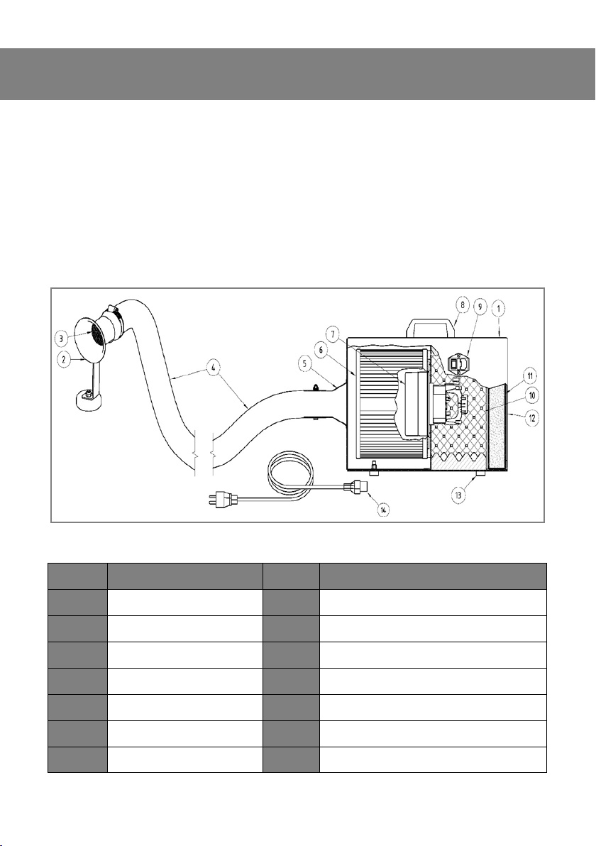
The SIP FX100 machine described in this booklet is a portable unit for the extracon, ltraon and deodorisaon of welding fumes in industry, automove workshops and for small welding fabricators.
Polluted air extracted by a brush motor with integrated aspirator posioned inside
the machine casing. Capture is done by an adjustable hood and through a 60mm
diameter exible hose which reaches a ltraon cartridge. Aer the fan, the fume
will be nally expelled. The nal deodorisaon is carried out through an acvated
carbon cell.
Item Descripon Item Descripon
1 Machine Casing 8 Handle
2 Adjustable Sucon Hood 9 Power Connecon - ON/OFF Switch
3 Fine Spark Arrestor 10 Sound-proong
4 Sucon Hose 11 Acvated Carbon Filter
5 Connecon 12 Exhaust Outlet
6 Main Filter Cartridge 13 Rubber Feet
7 Brush Sucon Motor 14 Mains Power Cable
Page 13
13
OPERATING INSTRUCTION
For correct use of the machine you must:
• Posion the machine near the source of the fumes, using the handle provided.
• Posion the sucon hood of the machine at the point where you want to
extract the fumes using the magnec base supplied.
• Posion the hood no more than 4” / 100mm from the welding fume source.
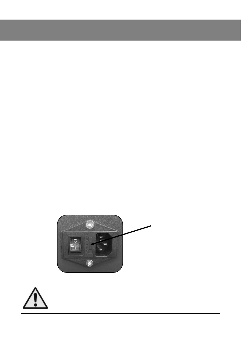
• Connect the supplied cable to the machine's power socket Fig.1.
• Insert the plug into a suitable electrical socket (check that the power and
supply match the rang label).
• Press the ON/OFF switch into the “I” posion. The switch is located on the
le side of the machine when looking at it from the acvated carbon side
(exhaust ange). The switch itself will light up;
• When you have nished with the extracon press the ON/OFF switch into
the “0” posion.
• Disconnect the electric plug from the power socket and if necessary also
disconnect the electric cable from the power socket on the machine; posion the machine in such a way as not to cause obstacles and / or problems
and in such a way that it is not a source of danger to normal acvies.
Fig.1
At the end of its use, do not leave the hose and the power cable on the
ground as they could become a trip hazard or get damaged.
Wear heat resistant gloves & PPE to prevent burns from high temperatures that can reach the sucon cap and hose.
Protecon Fuse
Assembly
Page 14
14
MAINTENANCE
REGULAR MAINTENANCE
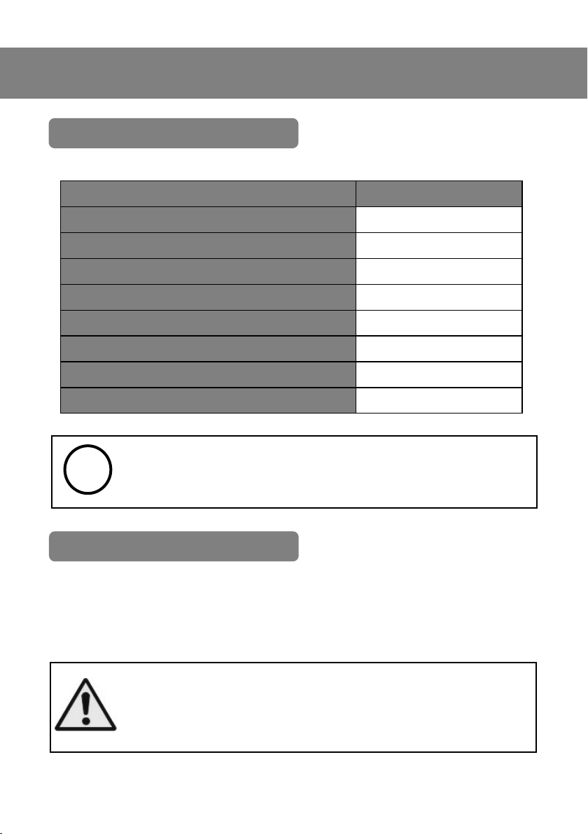
Descripon Frequency
Visual Inspecon of Sucon Hose Before every use
Hose Clamp Tightness Before every use
Mains ON/OFF Assembly Before every use
Mains Power Cable Before every use
Visual Inspecon of Filters Every 2 months
Cartridge Filter Replacement Every 6 months
Fine Hood Filter Replacement Every 6 months
Acve Carbon Filter Replacement Annually
NOTE: The frequency indicated is purely indicave and refers to
standard condions of use.
!
REPLACING THE FILTERS
With use, the sucon capacity of the machine tends to decrease as a result of the
progressive clogging of the lters. They are not regenerable and must be periodically
replaced.
ATTENTION: The machine could contain dusts which is harmful to
health. Repair, maintenance, lter replacement cleaning operaons
must be carried out by suitably trained personnel equipped with adequate personal protecve equipment (PPE): Gloves, Goggles and Facial lter mask.
Page 15
15
MAINTENANCE
NOTE: Do not disperse the lters used in the environment.
Deliver them to specialised disposal companies in accordance with
current legislaon.
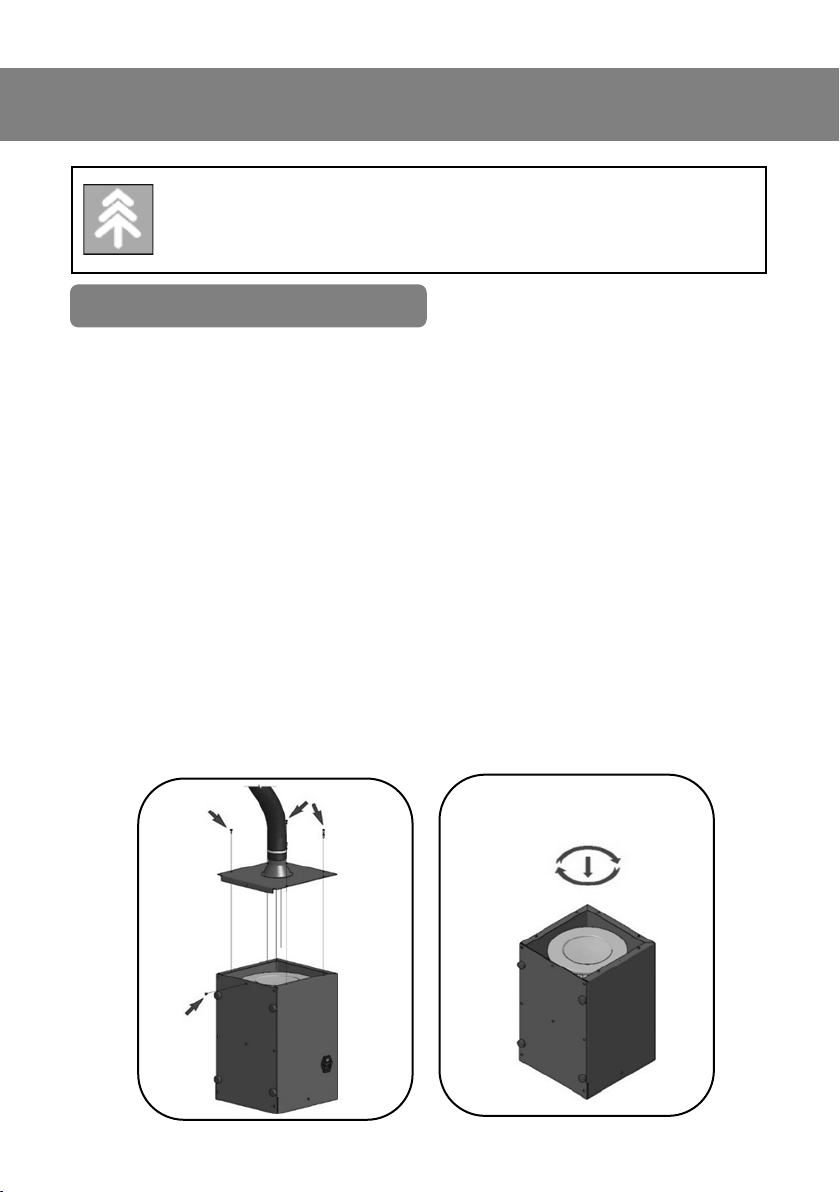
The cartridge lter is located inside the casing of the machine.
Access is from the sucon inlet, xed by means of a bayonet anchoring
system.
To replace it, follow the procedure below:-
• Remove the Sucon Intake Flange, unscrewing the self-tapping screws indi-
cated in Fig. A. Save the screws.
• Press the lter and, keep some pressure on it , turn it clockwise unl the
bayonet hooks disengage (about 1.5cm) (Fig. B);
• Remove and set aside the lter which will then be disposed of.
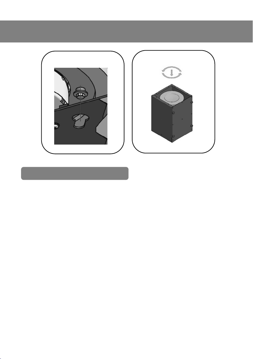
• Posion the new lter where the old one was, making sure that the 3 pins of
the bayonet coupling system correctly engage the 3 dedicated keyhole slots
(Fig. C);
• Press the lter and, keep some pressure on it, rotate it counterclockwise for
about 1.5cm in order to send the pins of the bayonet system into the dedicated seat (Fig. D);
• Check that the lter is correctly and rmly aached;
• Fix back the Sucon Intake Flange.
Fig. A
Fig. B
CARTRIDGE FILTER
Page 16
16
Fig. C
Fig. D
ACTIVE CARBON FILTER
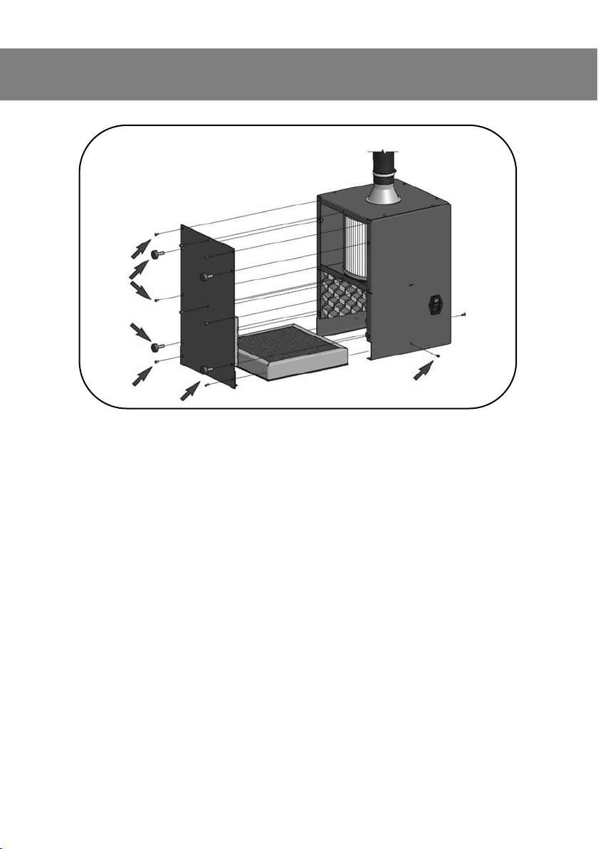
The acvated carbon lter is posioned in view in the rear part of the ma
chine, Fig. E, previously referred to as the exhaust ange.
To replace the lter follow the procedure below:
• Remove and keep the 4 rubber feet and the xing screws of the lower
ange of the machine.
• Remove the lter xing screws.
• Remove the lter from its seat and put it to one side: aerwards dispose of
it following local guidelines.
• Place the new lter in place of the old one, making sure that the sealed
edge of the gasket is facing the outside of the machine, bung up to the
sheet metal ange of the machine casing.
• Pressing the lter downwards in order to compress the gasket, make 3
Ø3.5 holes on the 3 sides of the lter in correspondence with the slots on
the machine casing.
• Apply 3 of the previously removed screws and lock the lter;
• Reassemble the lower ange of the machine xing it with the screws previ-
ously removed.
MAINTENANCE
Page 17
17
MAINTENANCE
Fig. E
Page 18
18
WIRING DIAGRAM
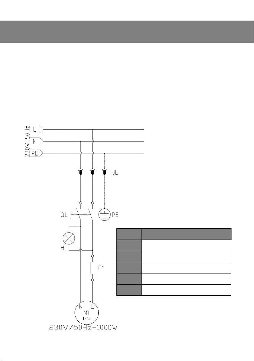
The SIP FX100 machine is equipped with an electric power socket with ignion
switch, power light and protecon fuses.
By pressing the switch, it directly powers the electric motor, starng the sucon
operaons.
At the same me the red LED lights up to indicate that the machine is powered
and switched on.
The following diagram shows the electrical wiring of the machine.
Item Descripon
JL Electric Power Cable
QL Bi-Polar Switch
HL RED Switch LED
F1 6.3A Fuse
M1 Motor 1100wa
Page 19

19
TROUBLESHOOTING
Problem Issue Remedy
Extractor fails to start
Blown Fuse
Voltage Too Low
Mains Cable Issue
Sucon Motor Issue
Test the fuse in the plug
& extractor.
Test Voltage.
Check & Replace.
Check & Replace.
The air is not suciently ltered
Ineecve lters Check the condion &
replace
The extractor has
poor / low sucon
Clogged / Dirty Filters
Physical Obstrucons
Damaged Hose
Motor Issue
Check the condion &
replace
Remove any foreign bod-
ies / obstrucons
Check hose and replace
if necessary
Check & Replace.
Circuit Breaker Trip-
ping
Earth Ground Fault
Motor Short Circuit
Check extractor insulaon with tester
Check and replace if nec-
essary
Page 20
20
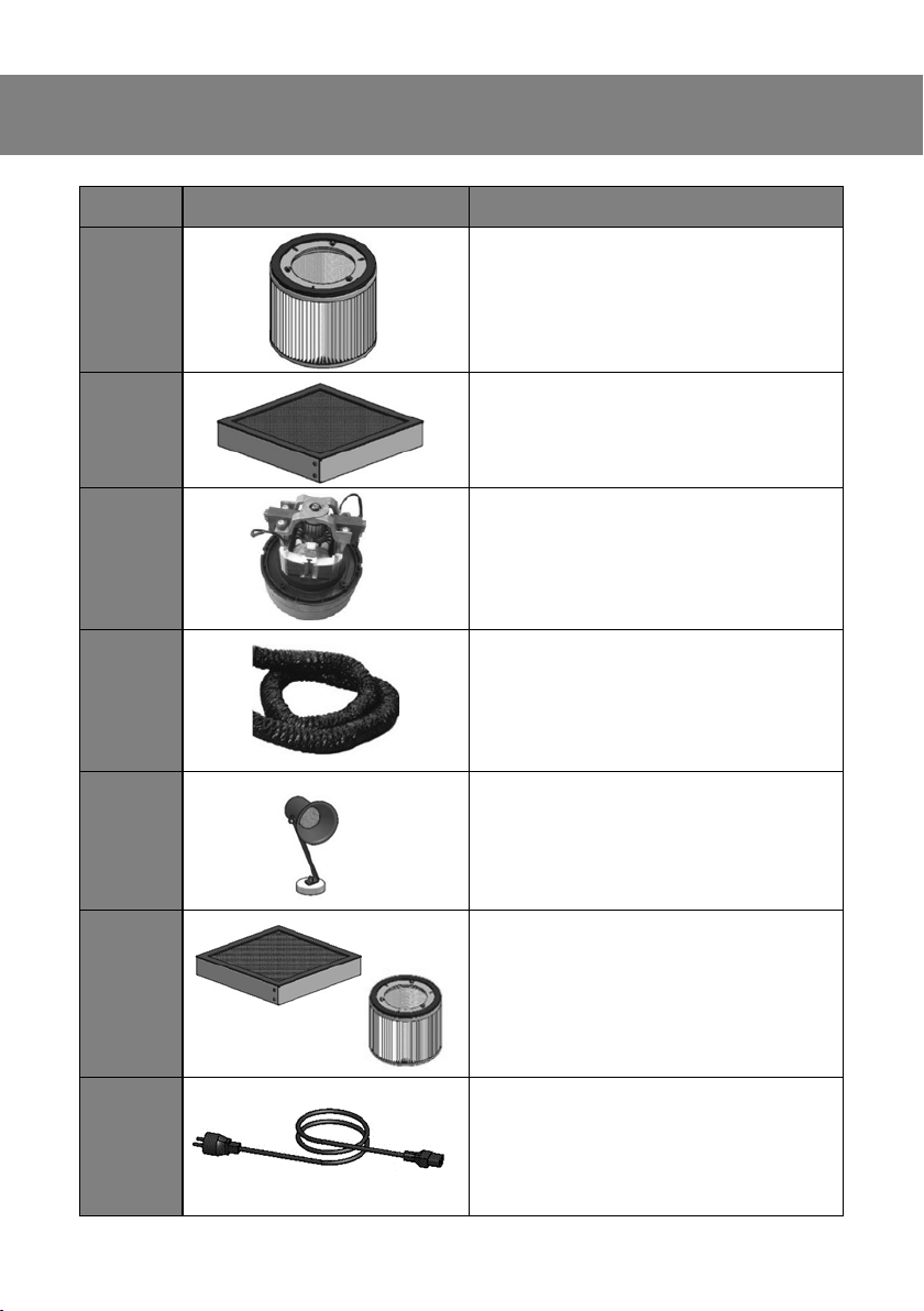
PARTS INFORMATION
Item Descripon SIP Code
1 CARTRIDGE FILTER
WE08-00052
2 CARBON FILTER
WE08-00053
3 MOTOR
WE08-00054
4 SUCTION HOSE
WE08-00055
5 SUCTION HOOD C/W MAGNETIC BASE
WE08-00056
6 CARTRIDGE & CARBON FILTER KIT
WE08-00057
7 MAINS INPUT CABLE
WE08-00058
Page 21

21
NOTES
Page 22
22
UK DECLARATION OF CONFORMITY
We
SIP (Industrial Products) Ltd
Gelders Hall Road
Shepshed Loughborough
Leicestershire
LE12 9NH
England
As the manufacturer within England, Scotland and Wales, we declare that the
SIP FX100 Welding Fume Extractor : SIP Code 05815
Conforms to the requirements of the following regulaon(s), as indicated:
Electromagnec Compability Regulaons 2016
Supply of Machinery (Safety) Regulaons 2008
Electrical Equipment (Safety) Regulaons 2016
The Restricon of the Use of Certain Hazardous Substances in
Electrical & Electronic Equipment Regulaons 2012
Signed.
Mr. Paul Ippaso
Managing Director
SIP (Industrial Products) Ltd
Date: 31 January 2024
Page 23
23
EU DECLARATION OF CONFORMITY
We
SIP Machinery Europe Ltd
Quayside Business Park
Dundalk
County Louth
Republic of Ireland
As the manufacturer within England, Scotland and Wales, we declare that the
SIP FX100 Welding Fume Extractor : SIP Code 05815
Conforms to the requirements of the following direcve(s), as indicated:
EMC 2014/30/EU
Machinery Direcve 2006/42/EC
Low Voltage Direcve 2014/35/EU
RoHS 2011/65/EU & 2015/863/EU
Signed.
Mr. Paul Ippaso
Managing Director
SIP (Machinery Europe) Ltd
Date: 31 January 2024
Page 24
24
FOR HELP OR ADVICE ON THIS PRODUCT
PLEASE CONTACT YOUR DISTRIBUTOR,
OR SIP
DIRECTLY ON:
TEL: 01509 500400
EMAIL:
or
www.sip-group.com
Please dispose of packaging for the product in a responsible
manner. It is suitable for recycling. Help to protect the environment, take the packaging to the local amenity tip and
place into the appropriate recycling bin.
Never dispose of electrical equipment or batteries in with
your domestic waste. If your supplier offers a disposal facility
please use it or alternatively use a recognised recycling agent.
This will allow the recycling of raw materials and help protect
the environment.
31January 2024
 Loading...