

Page 1
SIP Industrial Products Limited
Gelders Hall Road
Shepshed
Loughborough
Leicestershire
LE12 9NH
United Kingdom
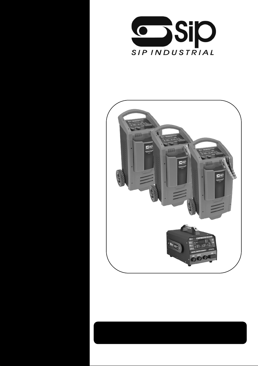
SIP Startmaster Digital Starter Chargers
DSC200B DSC250B DSC350B DSC600B
For help or advice please contact your
distributor, or sip directly on:
Tel.: 01509 500400
Email:
or
www.sip-group.com Please read and fully understand the instrucons in this manual before
operaon. Keep this manual safe for future reference.
SIP Code 03584 03585 03586 03587
1
Page 2

2
Page 3
CONTENTS
Page No Descripon
4- 7 Safety Informaon
8 Guarantee
8 - 10 Electrical Connecon
11 Technical Specicaon
12 - 13 Geng To Know Your Starter Charger
14 - 15 Assembly Instrucons
16 - 21 Operang Instrucons
22 Troubleshoong
23 Exploded Drawing 03584
24 Parts List 03584
25 Exploded Drawing 03585 03508 03587
26 Parts List 03585 03586 03587
28 UK Declaraon of Conformity
29 EU Declaraon of Conformity
3
Page 4

SAFETY INSTRUCTIONS
IMPORTANT: Please read the following instrucons carefully, failure to do so could
lead to serious personal injury and / or damage to the Starter / charger and anything connected to it.
When using your starter / charger, basic safety precauons should always be followed to
reduce the risk of re, electric shock, personal injury and / or damage to the starter /
charger. Read all these instrucons before operang the charger and save this user manual
for future reference.
SIP recommends that the starter / charger should not be modied or used for any applicaon other than that for which it was designed. If you are unsure of its relave applicaons do not hesitate to contact us and we will be more than happy to advise you.
These starter / chargers are designed for the charging of lead-acid baeries, and for starng
vehicles with lead acid baeries ed. They should not be used as a DC power source,
Baery Support Units or used to recharge non-rechargeable baeries. To do so may cause
re, electric shock, etc.
They are designed to be powered from a 230v ~ 50 / 60Hz supply, which is reliably connected to the buildings ground (earth) point.
If the supply cable needs to be extended, ensure the cross-seconal area of the wire in the
extension lead is of a sucient size for the supply of current over the distance required.
If the starter / charger is interrupted or damaged due to heavy impact etc., the baery
should be taken o charge immediately.
Do not dismantle the starter / charger - If repairs are required, they should be performed by a suitably qualied person. Incorrect reassembly may result in a re hazard and /
or electric shock.
Always disconnect the starter / charger from any connected baery and the mains supply
prior to cleaning the casing or changing fuses etc.
When connecng the starter / charger whilst the baery is sll connected to the vehicle -
connect the lead to the baery rst (normally +). The other connecon is to be made to the
chassis as far away as praccal from the baery and fuel line. (a spark can be generated
when connecng the second clip which can ignite baery or fuel gases). The starter /
charger is then to be connected to the mains supply. Once charging is complete, disconnect the starter / charger from mains supply rst, and
then remove the chassis connecon followed by the baery connecon.
During charging, baeries give o some hydrogen and oxygen creang a highly explosive
mix. Ensure adequate venlaon exists and avoid sparks, smoking, etc.
During baery maintenance ensure adequate clean water is available in the event of an acid
4
Page 5

SAFETY INSTRUCTIONS Cont...
spill. The liquid inside batteries is highly corrosive therefore ensure that it is not allowed to
make contact with the skin (especially eyes). In the event of contact, flush the area with
clean water and immediately consult a doctor.
Lead-acid batteries store a large amount of energy. Short-circuiting the battery or
charger terminals will cause the battery to try and release this energy immediately,
which can result in fire or personal injury. Prevent any metal object (or other conductive
material) from touching the + and – terminals of the charger or battery at the same
time.
KNOW YOUR STARTER / CHARGER: Read and understand the owner's manual and labels
affixed to the charger. Learn its applications and limitations, as well as the potential
hazards specific to it.
DO NOT USE THE STARTER / CHARGER IN DANGEROUS ENVIRONMENTS: Do not use your
starter / charger in damp or wet locations, or expose it to rain. Always provide adequate
space around the starter / charger.
KEEP CHILDREN AND UNTRAINED PERSONNEL AWAY FROM THE WORK AREA: All visitors
should be kept at a safe distance from the work area.
STAY ALERT: Always watch what you are doing and use common sense.
DISCONNECT THE STARTER / CHARGER FROM THE MAINS SUPPLY: When not in use.
DO NOT ABUSE THE MAINS LEAD: Never pull the mains lead it to remove the plug from the
mains socket. Keep the mains lead away from heat, oil and sharp edges. If the mains lead is
damaged, it must be replaced by the manufacturer or its service agent or a similarly
qualified person in order to avoid unwanted hazards.
HAVE YOUR STARTER / CHARGER REPAIRED BY A QUALIFIED PERSON: The starter-charger
is in accordance with the relevant safety requirements. Repairs should only be carried out
by qualified persons using original spare parts, otherwise this may result in considerable
danger to the user and void the warranty.
DANGER! Check that the starter / charger is in sound condition and good working order.
Take immediate action to repair or replace damaged parts.
5
Page 6

6
USE RECOMMENDED PARTS ONLY - Unapproved parts may be dangerous and will in-
validate the warranty.
WARNING! Only operate on a level and stable surface.
WARNING! Do not allow untrained persons to operate the starter /charger and do not oper-
ate the machine without all covers etc. correctly ed.
WARNING! RISK OF ELECTRIC SHOCK. Do not expose the starter / charger to water spray,
rain, dripping water or moisture of any kind.
Do not move or handle the charger when it is running.
SAFETY INSTRUCTIONS Cont...
Do not leave the charger unaended for long periods when in use. Switch the charger o
and unplug from the mains supply before leaving the work area.
Ensure that the starter / charger is correctly turned o when not in use and store in a safe,
dry area, out of reach of children.
Do not unplug the starter / charger to switch it o - always use the on/o switch. Keep all
combusble materials away from this starter / charger.
ALWAYS locate the starter / charger in an area of good venlaon. ALWAYS keep children
and animals away from charger.
Never stand on the charger.
DO NOT dismantle or tamper with the starter / charger, as this may be dangerous and
will invalidate the warranty.
If a problem with the starter / charger is experienced, or if the mains lead or plug
become damaged, contact your distributor for repair.
If the charger is used in a place of work all rules and laws etc. relang to the use of portable
electrical appliances should be followed.
WARNING: Risk of Electric Shock!
Use only the electrical power (voltage, current and frequency) specied on the model
plate of the starter / charger, or in this manual. If in doubt contact the manufacturer.
Page 7
SAFETY INSTRUCTIONS Cont...
Use only a three-prong, grounded mains supply socket.
ALWAYS unplug the starter / charger when not in use.
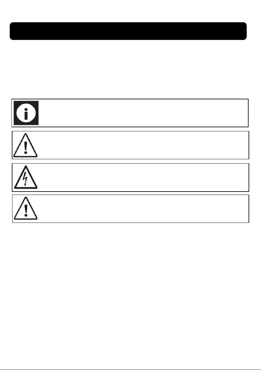
Safety Symbols Used Throughout This Manual.
Note: Supplementary informaon.
Danger / Cauon: Indicates risk of personal injury and/or the possibility of
damage.
Warning: Risk of electrical injury or damage!
CAUTION: The warnings and cauons menoned in this user manual can not cover all possible
condions and situaons that may occur. It must be understood by the operator that common
sense and cauon are factors which cannot be built into this product, but must be applied.
7
Page 8
GUARANTEE
Guarantee:
These SIP starter / chargers are covered by a 24 month parts and labour warranty covering
failure due to manufacturers defects. This does not cover failure due to misuse or operang the charger outside the scope of this manual - any claims deemed to be outside the
scope of the warranty may be subject to charges Including, but not limited to parts, labour
and carriage costs. Consumable items such as fuses are not covered by the warranty.
In the unlikely event of warranty claims, contact your distributor as soon as possible.
Note: Proof of purchase will be required before any warranty can be
honoured
ELECTRICAL CONNECTION
WARNING! It is the responsibility of the owner and the operator to read, understand
and comply with the following:
You must check all electrical products, before use, to ensure that they are safe.
You must inspect power cables, plugs, sockets and any other connectors for wear or damage.
You must ensure that the risk of electric shock is minimised by the installaon of appropriate safety devices; A residual current circuit Breaker (RCCB) should be incorporated in
the main distribuon board. We also recommend that a residual current device
(RCD) is used. It is parcularly important to use an RCD with portable products that are
plugged into a supply which is not protected by an RCCB. If in any doubt consult a qualied electrician.
8
Page 9
ELECTRICAL CONNECTION Cont...
Connecting to the power supply:
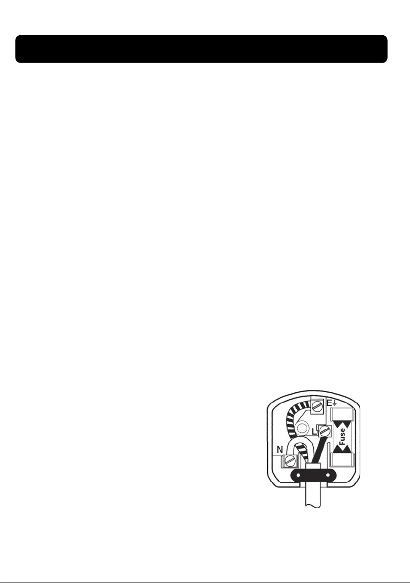
The SIP starter / charger 03584 DSC200B is fitted with a standard 230v ~ 13 amp type
plug; the rest come without a plug fitted as they all need a supply above 13 amps to work
correctly (see individual specifications). Before using the start-er / charger, inspect
the mains lead and plug to ensure that neither are dam-aged. If any damage is visible
have the starter / charger inspected / repaired by a suitably qualified person. If it is
necessary to replace the plug a heavy duty impact resistant plug would be preferable.
The wires for the plug are coloured in the following way:
Yellow / green
Earth
Blue
Brown Liv
As the colours of the wires may not correspond with the markings in your plug, proceed
as follows: The wire which is coloured blue, must be connected to the terminal marked
with N or coloured black. The wire which is coloured brown, must be connected to the
terminal, which is marked L or coloured red. The wire which is coloured yellow / green
should be connected to the terminal which is col-oured the same or marked.
Neutra
l
e
Always secure the wires in the plug terminal carefully and tightly. Secure the cable in the
cord grip carefully.
9
Page 10
10
ELECTRICAL CONNECTION Cont...
Warning: Never connect live or neutral wires to the earth terminal of the plug.
Only t an approved plug with the correct rated fuse. If in doubt consult a
qualied electrician.
Note: Always make sure the mains supply is of the correct voltage and amperage
and the correct fuse protecon is used. In the event of replacing the fuse always
replace the fuse with the same value as the original.
Note: If an extension lead is required in order to reach the mains supply;
ensure that this too is rated for the correct voltage and fuse rang.
Note: The cross secon of the extension lead should be checked so that it is
of sucient size so as to reduce the chances of voltage drops.
All the Startmasters can be used on a 230v 13A supply for charging only!
They will require a larger supply for Jump Starng an engine.
Page 11
TECHNICAL SPECIFICATION
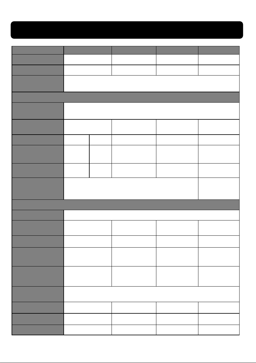
Model 03584 03585 03586 03587
Supply 230v 50Hz 230V 50Hz 230V 50Hz 230V 50Hz
Baery Voltage 6, 12 & 24v 12 & 24v 12 & 24v 12 & 24v
Funcons 10 Stage Charging, Boost & Support
CHARGING:
baery type:
Charging Input -
connuous
Baery Voltage 6/12V 24V 12V & 24V 12V & 24V 12V & 24V
1000W 1000W 1400W 2000W
All Types of 12V Lead-acid & 12V Lithium Ion
Baeries(4-cell LiFePO4) and 24V Lead-acid Baeries
Charging Current
Boost Charging
Current
Max Baery Capacity 350Ah 550Ah
5A @6v
10A@12v
25A
10A 5A/15A 5A/20A 10A/30A
20A 25A
35A
50A
JUMP START:
Start Voltage > 1V
Start Input - 5secs 4.5kW 6kW 7.5kW 10kW
Fuse 100A 100A 200A 300A
Max Start Current -
Fully Discharged Baery
Max Start Current -
Medium Charged
Baery
Protecon & Ambient
Temperature
Product Dimensions 265 x 409 x 204mm 293 x 214 x 613 mm 293 x 214 x 613 mm 293 x 214 x 613 mm
Boxed Dimensions 458 x 293 x 315mm 358 x 358 x 600 mm 358 x 358 x 600 mm 358 x 358 x 600 mm
200A 280A 400A 620A
150A 200A 300A 500A
IP20 / 0oC - 20OC
Weight - GW/NW 12.3 / 11.5kg 16.8 / 15.5 kg 21.1 /18.69 kg 25.6 / 24.1kg
11
Page 12
GETTING TO KNOW YOUR STARTER / CHARGER
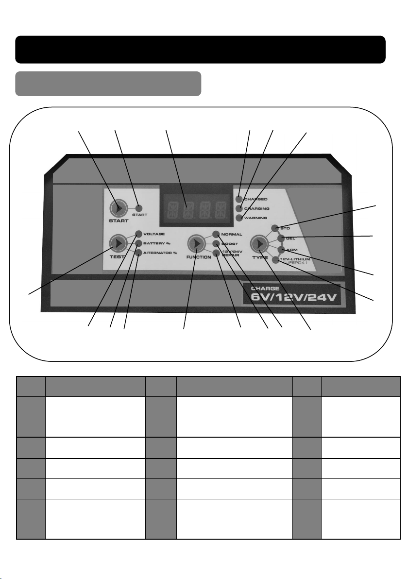
CONTROL PANEL
A
B
E
DC
F
S
R Q
P
O
N M L K
Item Descripon Item Descripon Item Descripon
Engine Start Buon
A
GEL Baery LED
H
Funcon Selector
O
G
H
I
J
Engine Start Indicator
B
Digital Display
C
Charged LED
D
Charging LED
E
Warning Indicator LED
F
Standard Baery LED
G
AGM Baery LED
I
12V Lithium Baery LED
J
Baery Type Selector
K
Normal (5/10A)Charge LED
L
Boost (20/25A) Charge LED
M
Repair LED
N
12
Alternator % LED
P
Baery % LED
Q
Voltage LED
R
Test Selector
S
Page 13
13
GETTING TO KNOW YOUR STARTER CHARGER Cont...
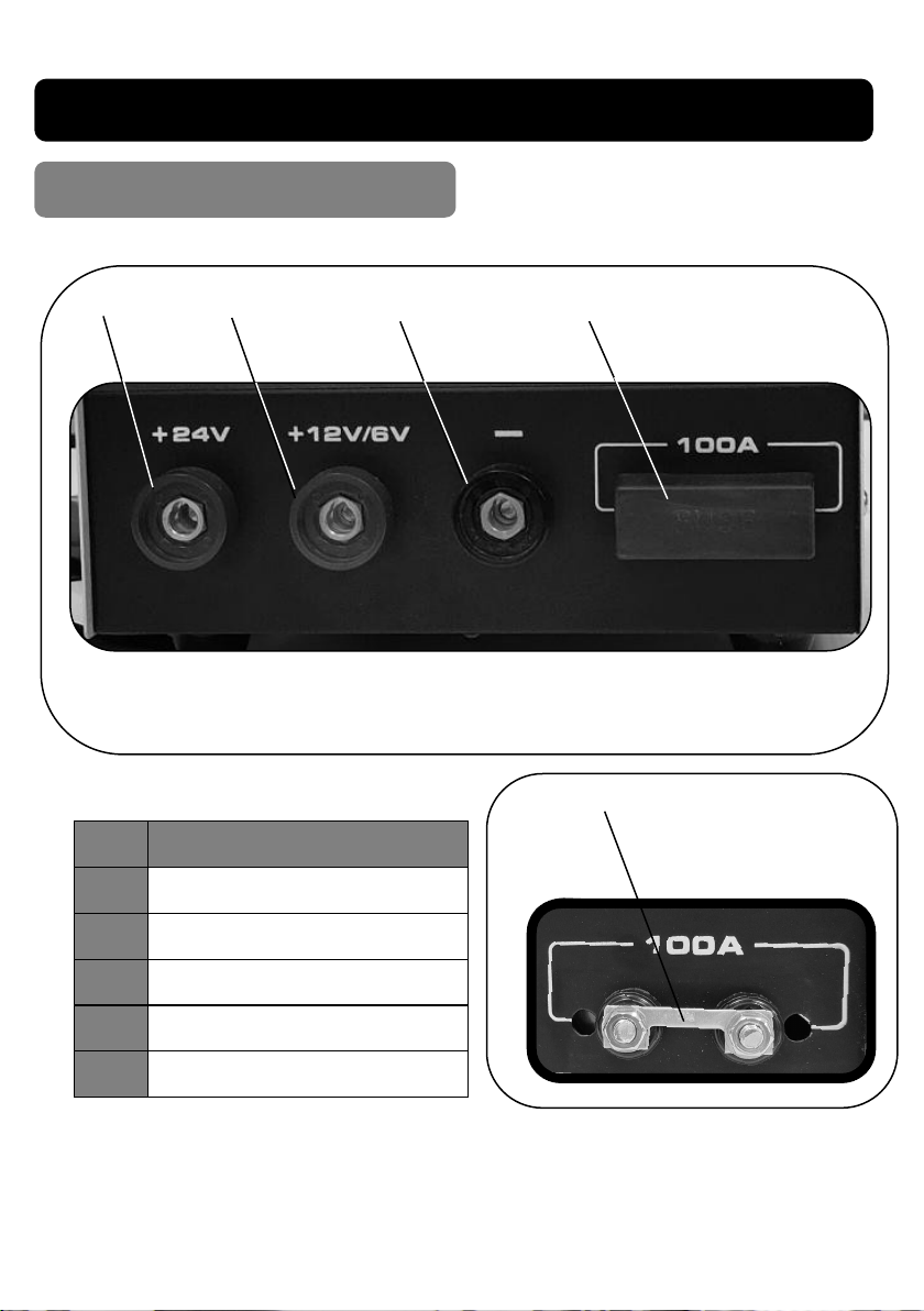
SOCKETS & FUSE ASSEMBLY
Item Descripon
1 Red Posive Socket 24v
2 Red Posive Socket 6/12v
3 Black Negave Socket
4 Fuse Cover
5 Fuse Link
1
2
3
4
5
Page 14
ASSEMBLY
03584
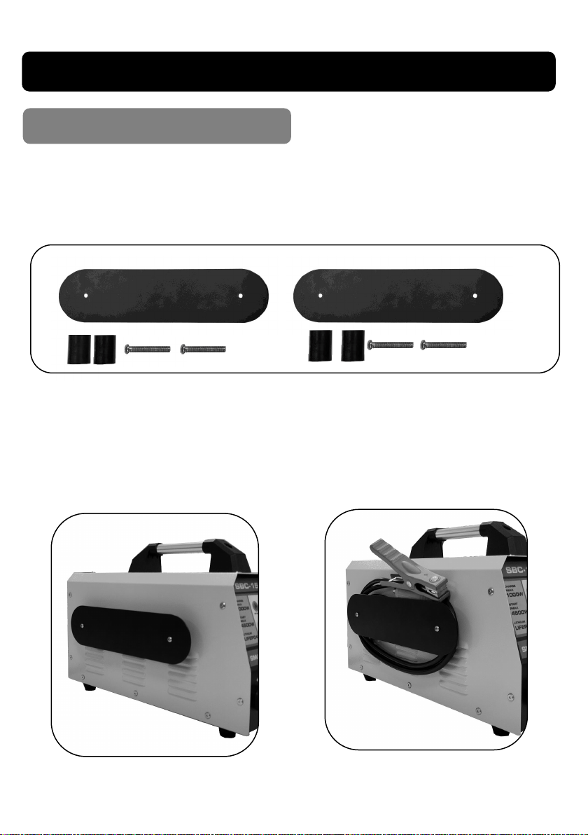
CONTENTS:-
1 x 03584 Starter Charger: 2 x Cable Tidy Brackets: 4 x Screws:
2 x Bracket Stand-Os: 1 x Negave Cable: 1 x Posive Cable
• Fit cable dy brackets to each side of the Starter Charger using one
bracket, 2 spaces & 2 screws per side. (Fig.1)
• Wrap cable around bracket. (Fig.2)
Fig.1
Fig.2
14
Page 15
ASSEMBLY Cont...
03585 03586 03587
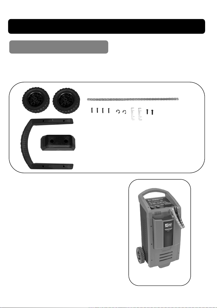
2 x Wheels: 1 x Axle: 1 x Handle: 1 x Foot: 4 x Long Screws:
2 x Short Screws: 2 x E - clips: 2 x Fuses
**The 2 fuses are spare and not required for
assembly.
• Fit the handle using the 4 long self tapping screw.
• Push the axle through the chassis .
Place the wheels on to the axle and
retain in place using the E-Clips sup-
plied.
• Finally t the front foot using the 2
short self tapping screws.
• Finished assembly should look like
Fig.3.
15
Fig.3
Page 16
OPERATING INSTRUCTIONS
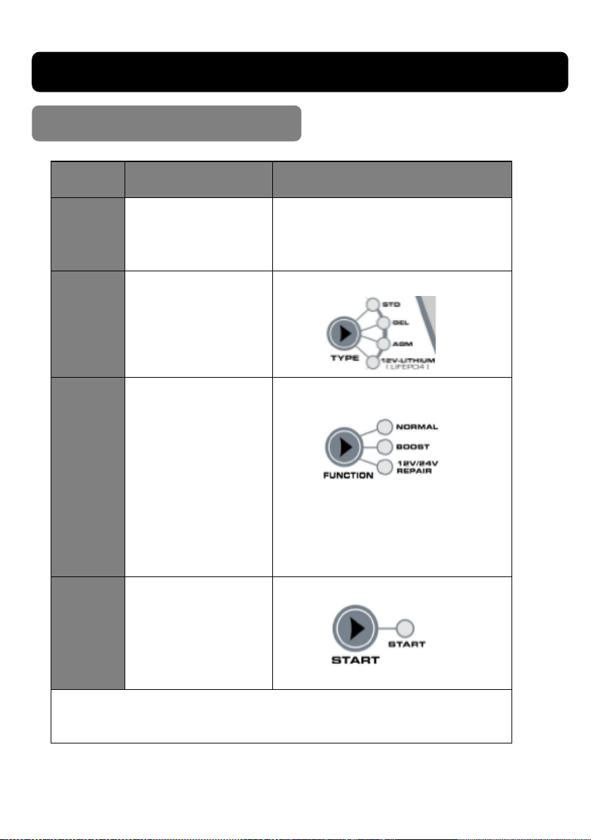
Charging a Baery
Step No. Selecon Result
1
2
3
ENGINE
START
Make Baery
Connecons
Select Baery Type
Select Charging
Mode
Select Engine Start
Funcon
Connect 6/12v baery to 6*/12v Termi-
nal / Connect 24v baery to 24v Terminal: Display shows baery voltage
Corresponding LED will light.
Corresponding LED will light.
NORMAL - “CHARGING” Displayed
BOOST - “CHARGING” Displayed
REPAIR - “REPAIR-ON” Displayed
LED will light.
“START-READY” Displayed.
NOTE: When display shows OFF, the mode can be selected in FUNCTION
SELECTION
*Only 03584 model has a 6v opon.
16
Page 17
ASSEMBLY Cont... OPERATING INSTRUCTIONS Cont...
CAUTION: Do not leave the baery connected to the charger once the charging has
nished, this may cause excessive heang of the cells and the electrolyte to “boil”. If
this happens during charging select a lower seng or stop the charge.
Danger / Cauon: Do not touch the posive clamp (Red) with the negave
clamp (Black) together to check the starter / charger output – this may
cause the internal fuse, or the mains fuse to blow.
Important: For posive grounded vehicles connect the - (black) clamp to the
baery negave terminal and the + (red) clamp to the baery posive terminal
or the vehicle chassis.
Note: If the baery is sll connected to the vehicle - connect one lead to the baery
rst (normally +). The other connecon is to be made to the chassis as far away as
praccal from the baery and fuel line.
Important: Check with the manufacturer of the vehicle that the baery can be
charged whilst sll connected to avoid any unwanted damage to the vehicle.
FUNCTION SELECTION:
Press the Function button and select current range (see page 11) :-
NORMAL - Low Current NORMAL - High Current
BOOST Charge Current 12v REPAIR
Mode Baery Types
NORMAL
NORMAL
BOOST
Charging: 12v & 24v Lead Acid
12v Lithium Ion (4 cell LiFePO4)
Charging: 12v & 24v Lead Acid
12v Lithium Ion (4 cell LiFePO4)
Charging: 12v & 24v Lead Acid
12v Lithium Ion (4 cell LiFePO4)
REPAIR Charging: 12v & 24v Lead Acid
NOTE: The charger is a 10 step smart charger and may not allow you to select high charging current once it has
analysed the baery condion.
17
Page 18
OPERATING INSTRUCTIONS Cont...
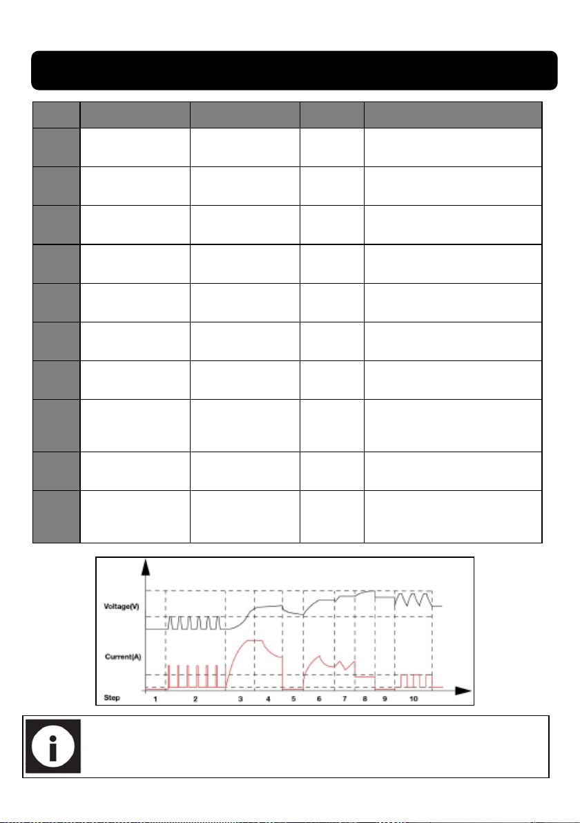
Step Mode Descripon Display Read-Out LED Status
1 Analysing 1
2 De-sulphaon
3 De-sulphaon 2
Controlled Current
4
5 Analysing 2
6
7
8 Absorpon
9 Analysing 3
10 Maintenance
Charge
Constant Output
Charge
Recovery Cycle
Charge
Analysing-1
BATT12/24
Charging
BATT 12/24
Charging
BATT 12/24
Charging
BATT 12/24
Analysing-2
BATT12/24
Charging
BATT 12/24
Charging
BATT 12/24
Charging
BATT 12/24
Analysing-3
BATT12/24
Maintenance
BATT 12/24
Charging
LED
Charging
LED
Charging
LED
Charging
LED
Charging
LED
Charging
LED
Charging
LED
Charging
LED
Charging
LED
Charged
LED
Charging State
Checks that the baery is connected
Pulsing charge to remove sulphate
Gradually increases charging
rate
Intelligently adjust the charging current
Checks that the baery can
absorb the charge
Constant voltage charging
Absorbs charge / compensates
accordingly
Charges with constant trickle
current for max baery voltage
Test to see if baery can hold
the charge
Constant monitoring - Trickle
current charge applied once
threshold voltage is reached
For 03584 model display Read-Out will show 6,12 & 24v.
18
Page 19
ASSEMBLY Cont... OPERATING INSTRUCTIONS Cont...
Engine Start Funcon
Important: Check with the manufacturer of the vehicle to be started that it
is safe to use a starter / charger without causing damage to the electrical
system.
Follow all safety instructions & precautions for charging a battery. Wear
eye / face protection and protective clothing.
1. Ensure the mains supply to the starter / charger is off.
2. Check battery liquid and top up if required. Unsealed batteries only.
3. Connect the + (red) lead to the correct voltage socket on the starter / charger depending
on the voltage (12 or 24) of the vehicle to be started.
4. Connect one of the leads to the battery first (normally +). The other connection is to be
made to the chassis as far away as practical from the battery and fuel line (a spark can be generated when connecting the second clip which can ignite battery or fuel gases).
5. If the battery voltage is low or in extremely cold weather charge the battery for
15minutes.
6. Connect the starter / charger to the mains supply and turn on, then charge as
shown on pages 16 & 17.
7. After 15 minutes switch off the charger.
8. With the leads still connected prepare to start the engine.
9. Switch on the starter / charger. Press the engine start button and the start LED will
illumi-nate and the display show “START-READY”.
10. Turn the ignition key. As soon as cranking is detected the starter / charger will
automatical-ly deliver up to it’s maximum output as required by the starting system for 10
Seconds.
11. After the 5 second cranking period the charger will automatically enter a 240second cool
down cycle. The display counts down from 240 - 0.
You will not be able to adjust any setting using the buttons during this cycle.
19
Page 20
OPERATING INSTRUCTIONS Cont...
12. Aer the cool down cycle is complete the display will return to “START-READY”.
13. If the vehicle did not start then charge the baery again on BOOST. Then perform
steps 9 -11 again.
14. If the engine turns over but does not start then the problem lies elsewhere - do
not connue to aempt to crank using the starter / charger unl the problem has
been resolved.
Never try and start a vehicle without a battery fitted.
Damage could be caused the vehicles electrical system.
Never touch the clamps together in Engine Start mode.
Never remove the clamps from the battery in Engine Start mode.
Voltage Tester
When the starter / charger is inially switched on it will be in voltage test mode.
It will display the baery voltage.
Press the test buon again and it will show the baery charged percentage (%).
The voltage test funcon is designed only to test baery voltage.
20
Page 21

ASSEMBLY Cont... OPERATING INSTRUCTIONS Cont...
Alternator Tester
With the charger switched off, connect the battery as in the charging & starting sec-tions.
Switch on the starter / charger.
Press the test button until the “Alternator %” LED illuminates.
Start the vehicle and turn on the vehicles headlights. If you get a reading of 0 - 100%, then
the alternator is working ok.
If the reading is “LO” or “HI” have the charging the system checked by a qualified technician.
21
Page 22
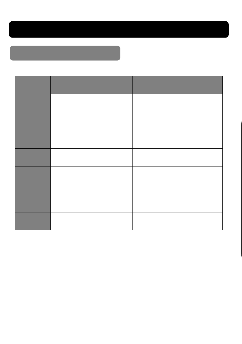
TROUBLESHOOTING
Error Displays
Digital
Display
Symptom Remedy
E01 Connecons are reversed.
E02
E03
Output current stopped ~
Charger overheated.
Baery won't store charge ~
Dead baery
No baery connected.
E04
baery voltage <1 volt.
Red & black clamps are
touching.
BATT -
MISMATCH
Charging in 12v mode
on 24v battery. **
Connect to the correct baery
terminals
Leave switched and do not un-
plug.
charger will re-start when
cooled.
Replace baery.
Try REPAIR mode.
Connect clamps to baery ter-
minals.
Clean baery terminals
Replace baery
Prevent clamps touching
Connect correctly.
** NOTE: SIP Model 03584 "Charging in 6v mode on 12/24v battery"
22
Page 23
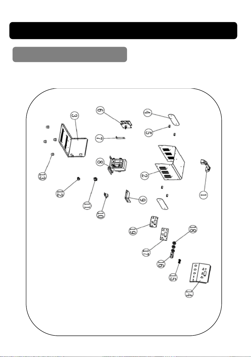
EXPLODED DRAWING
03584
23
Page 24
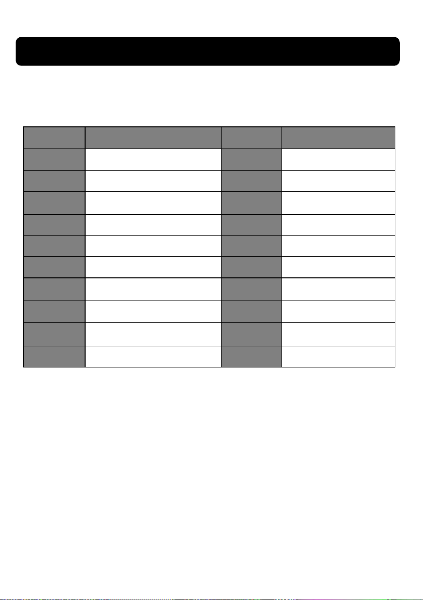
PARTS LIST
Ref. No Descripon Ref. No Descripon
1.
2.
3.
4.
5.
6.
7.
8.
9.
10.
Handle
Top Cover
Boom Case
Cable Tidy
Bracket Stand-Os
Recer Bridge
Recer Bridge Bracket
Transformer
Main PCB
Relay
11.
12.
13.
14.
15.
16.
17.
18.
19.
On / O Switch
Cable Strain Relief
Foot
Front Panel
Fuse
Fuse Cover
Panel PCB
Quick Socket
Control Panel
24
Page 25
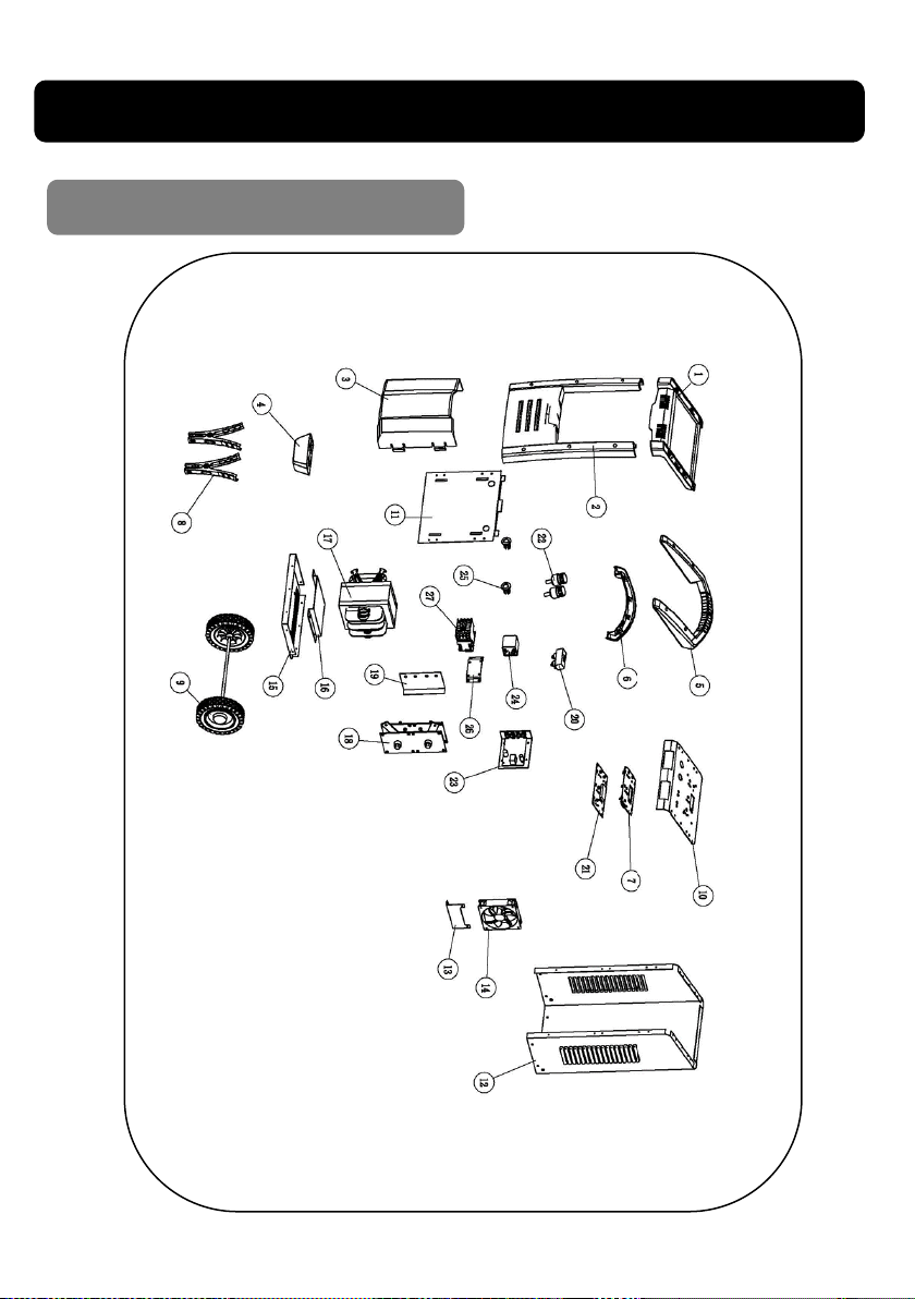
25
EXPLODED DRAWING
03585 03586 03587
Page 26
PARTS LIST
Ref. No Descripon Ref. No Descripon
1. Top Panel 15. Boom Plate
2. Front Cover 16. Transformer Base Pate
3. Front Storage Cover 17. Transformer
4. Foot 18. Recer Bridge
5. Handle 19. Recer Bridge Bracket
6. Lower Handle 20. Fuse Cover
7. Control Panel 21. Control PCB
8. Baery Clamps 22. 12/24v Terminal
9. Wheels 23. Circuit Board Heat Sink
10. Top Panel 24. Relays
11. Front Panel 25. Cable Strain Relief
12. Back Cover 26. Contactor Bracket
13. Fan Bracket 27. Contactor
14. Fan
26
Page 27

27
NOTES
Page 28

28
NOTES
Page 29

29
NOTES
Page 30

UK DECLARATION OF CONFORMITY
We
SIP (Industrial Products) Ltd
Gelders Hall Road
Shepshed Loughborough
Leicestershire
LE12 9NH
England
As the manufacturer within England, Scotland and Wales, we declare that the
SIP Startmaster DSC200B Digital Starter Charger Item No.03584
SIP Startmaster DSC250B Digital Starter Charger Item No. 03585
SIP Startmaster DSC350B Digital Starter Charger Item No. 03586
SIP Startmaster DSC600B Digital Starter Charger Item No. 03587
Conforms to the requirements of the following regulaon(s), as indicated:
Electrical Equipment (Safety) Regulaons 2016
Electromagnec Compability Regulaons 2016
The Restricon of use of Certain Hazardous Substances in
Electrical and Electronic Equipment Regulaons 2012
And the following harmonised standard(s):
BS EN IEC 60335-2-29:2021+A1:2021
BS EN 60335-1:2012+A11:2014+A13:2017+A1:2019+A2:2019+A14:2019+A15:2021
BS EN 62233:2008+AC:2008
BS EN55014-1:2021
BS EN55014-2:2021
BS EN IEC 61000-3-2:2019+A1:2021
BS EN 61000-3-3:2013+A1:2019+A2:2021
Signed.
Mr. Paul Ippaso
Managing Director
SIP (Industrial Products) Ltd
Date: 06June 2023
30
Page 31

EU DECLARATION OF CONFORMITY
SIP Machinery Europe Ltd
Quayside Business Park
County Louth
As the manufacturer within England, Scotland and Wales, we declare that the
SIP Startmaster DSC200B Digital Starter Charger Item No. 03584
SIP Startmaster DSC250B Digital Starter Charger Item No. 03585
SIP Startmaster DSC350B Digital Starter Charger Item No. 03586
SIP Startmaster DSC600B Digital Starter Charger Item No. 03587
Conforms to the requirements of the following direcve(s), as indicated:
2014/35/EU Low Voltage Direcve
2014/30/EU Electro-Magnec Compability Direcve
2011/65/EU & 2015/863/EU RoHS Direcve
We
Dundalk
And the following harmonised standard(s):
EN IEC 60335-2-29:2021+A1:2021
EN 60335-1:2012+A11:2014+A13:2017+A1:2019+A2:2019+A14:2019+A15:2021
EN 62233:2008+AC:2008
EN55014-1:2021
EN55014-2:2021
EN IEC 61000-3-2:2019+A1:2021
EN 61000-3-3:2013+A1:2019+A2:2021
Signed.
Mr. Paul Ippaso
Managing Director
SIP (Industrial Products) Ltd
Date: 06June 2023
31
Page 32
Please dispose of packaging for the product in a re-
sponsible manner. It is suitable for recycling.
Help to protect the environment, take the packaging
to the local amenity tip and place into the appropriate recycling bin.
Never dispose of electrical equipment or batteries in
with your domestic waste.
If your supplier offers a disposal facility please use it
or alternatively use a recognised recycling agent.
This will allow the recycling of raw materials and help
protect the environment.
Ref: 07July2023 Revision 4
For help or advice please contact your
distributor, or sip directly on:
Tel.: 01509 500400
Email:
or
www.sip-group.com
32
 Loading...