

Page 1
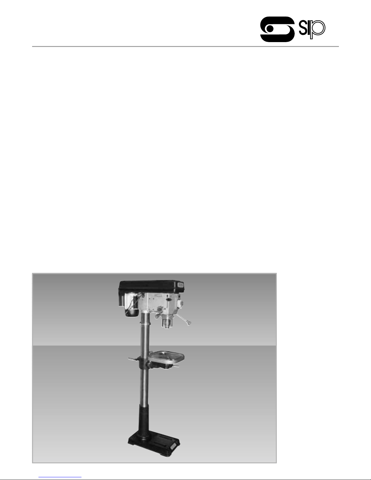
Manual
Pillar Drill
Dr ill Press
Manual: 060120/00001
Page 2

Prefix
ALWAYS READ INSTRUCTIONS BEFORE OPERATING THIS PRODUCT.
The data and advise given in this document apply when the machine is sold and used for the stated application or
applications. The machine is not sold as suitable for any other application. Use of the machine for applications other
than stated in this document may give rise to risks not mentioned.
If you have purchased this machine for supply to a third party for use at work, it is your duty to take all the
necessary steps to ensure that any person using this machine is provided with the information in this document.
If you are an employer, it is your duty to tell your employees and others who may be affected by any hazards
described in this document and of any precautions, which should be taken.
The information, data and recommendations contained in this document are believed to be accurate and up to
date at the time of compilation. It is essential that you read the whole of this document before using this machine
and ensure that only persons who have read the whole of this document are permitted to do so, after putting into
effect the safety precautions for the hazards identified.
Failure to understand and apply the requirements indicated in this document could result in personal injury and
damage to the machine.
2
Page 3

PAGE
TECHNICAL SPECIFICATION......................................................................4
SAFETY ....................................................................................................6
INSTALLATION AND ASSEMBLY ..................................................................7
OPERATION ............................................................................................9
ADJUSTMENTS ........................................................................................10
MAINTENANCE ......................................................................................11
WIRING DIAGRAMS ................................................................................12
ENVIRONMENTAL POLICY........................................................................16
Table of Contents
3
Page 4
Technical Specifications
4
A
B
C
D
1
2
3
4
5
7
8
9
6
Page 5

Technical Specifications
5
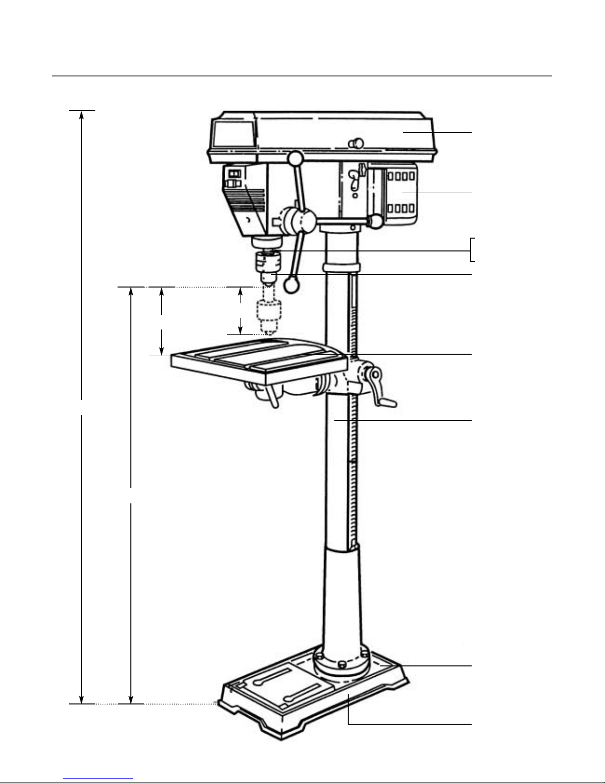
MODEL B13-5 B16-5 B16-16 F16-16 B16-16L F16-16L F25-16 F32-12
A HEIGHT
(MM)
B MAX DIST.
CHUCK TO
BASE (MM)
C MAX DIST.
CHUCK TO
TABLE (MM)
D SPINDLE
TRAVEL
(MM)
1 SPEED
(RPM)
2 MOTOR
(HP)
3 SPINDLE
TAPER
4 COLLAR
DIAMETER
(MM)
5 DRILL
CAPACITY
(HP)
6 TABLE
SIZE
(MM)
7 COLUMN
DIAMETER
(MM)
8
BASE
SIZE
(MM)
9 WEIGHT
(KG)
DIMENSIONSTECHNICAL SPECIFICATIONS (REFER TO DRAWING ON PAGE 4)
580 850 1000 1640 1060 1630 1640 1710
245 490 548 727 600 1154 1136 1075
165 370 371 727 350 668 640 595
50 60 80 80 80 80 80 120
5 5 16 16 16 16 16 16
(500-2500) (460-2480) (190-3000) (190-3000) (190-3000) (190-3000) (160-3000) (120-3480)
1/2 1/2 3/4 3/4 3/4 3/4 1.5 2
JT33 MT2 MT2 MT2 MT2 MT2 MT3 MT4
48 55 55 55 60 60 80 75
0.8-13 3-16 3-16 3-16 3-18 3-18 3-25 5-32
165 x 164 198 x 196 300MM ROUND 290 x 290 290 x 290
300MM ROUND
425 x 475
48 59.5 73 73 73 73 80 92
300 x 200 346 x 211 450 x 300 456 x 305 456 x 305 456 x 305 498 x 350 620 x 420
21 33 60 63 63 70 91 140
Page 6

Safety Infor mation
6
BEFORE OPERATING THIS UNIT, YOU MUST PAY SPECIAL ATTENTION TO
THE SAFETY NOTICES GIVEN BELOW.
ELECTRICAL
1. Electrical repairs must only be carried out by a qualified or suitably trained person.
2. We strongly advise that access to the interior of the unit be restricted to trained personnel only and that operating
the unit with the covers removed be avoided.
3. The unit must be correctly installed (See INSTALLATION )
SAFETY RULES FOR DRILLING
1. Caution. This drilling machine is intended for use only with drill bits the use of other accessories may be hazardous
make sure they are suitable and safe for use with your drill. Ensure that at all times the work area is well lit.
2. Correct drilling speeds. Factors, which determine the best speed to use in any drilling machine operation, are: Kind
of material being worked, size of the hole and type of drill or other cutter, and quality of cut desired. The smaller the
drill size, the greater the required R.P.M. In soft materials, the speed should be higher than for hard materials.
3. When drilling metal use clamps to hold the work. To avoid injury, the work should never be held with the bare hands.
4. The work must be clamped firmly while drilling. Any tilting, twisting or shifting results not only in a rough hole but also
increases the hazard, which could result in injury or drill breakage. For flat work lay the piece on a wooden base
and clamp it firmly down against the table to prevent it from turning If the piece is of irregular shape and cannot be
laid flat on the table, it should be securely blocked and clamped.
5. Remove key from chuck after adjustment.
6. Secure the base of the drill to the work bench or work table before using the drilling machine if the work is heavy or
large and likely to cause the drill to tip over, use additional supports as appropriate under and around the work.
8. Use only the chuck key provided by the manufacturer or a duplicate of it.
9. Always switch off the machine and isolate from the mains supply before opening the belt cover and changing
position of V belt or carrying out any adjustment or maintenance.
GENERAL SAFETY RULES
1. Keep all guards in place and in full working order.
2. Keep work area clean and tidy. Cluttered areas and benches invite accidents.
3. Do not use in damp or wet conditions, or expose the pillar drill to rain.
4. Keep children away. All visitors should be kept at a safe distance from the working area.
5. Do not force the tool or attachment to do a job for which it was not designed.
6. Use the right tool. It will do the job better and safer at the rate for which it was designed.
7. Wear proper clothing. No loose clothing, gloves, neckties, rings bracelets, or other jewellery as these may be caught
in moving parts. Non-slip footwear is also recommended. Wear protective hair covering to contain long hair.
8. Always use safety glasses.
9. Do not over reach. Keep proper footing and balance at all times.
10. Maintain tools. Keep tools sharp and clean for best and safest performance. Follow instructions for lubricating and
changing accessories.
11. Disconnect from the mains supply before servicing and when changing accessories such as drill bits.
12. Never stand on the drill press as serious injury could occur if the machine is tipped or if the cutting tool is
unintentionally contacted.
13. Check for damaged parts. Before using the drill press, a guard or other part that is damaged should be carefully
checked to determine that it will operate properly and perform its intended function, check for alignment of moving
parts, binding of moving parts, breakage of parts, mountings, or any other condition that may affect the machines
operation. A guard or any other part that is damaged should be immediately replaced.
14. Never leave drill running unattended. Turn the power off. Do not leave tool until the machine has came to a
complete stop.
Page 7

Installation
Your drilling machine is supplied as an easily assembled kit of major sub assemblies. Unpack the carton(s) carefully
and check you have the following parts. Allowing for variations of models.
Head assembly with motor (1)
Table assembly (1)
Column assembly with flange (1)
Drill press foot casting (1)
Feed handles and knobs (3+3)
Column fixing Bolts (4)
Drill chuck assembly (1)
Chuck key (1)
Chuck safety guard (1). (Usually stored inside the belt cover).
If you do not have any of these parts please call your supplier.
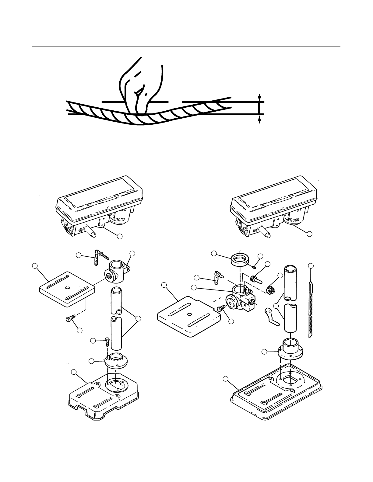
ASSEMBLY (Refer to Assembly Diagram Page X)
NB: Larger models may require two or more people to assembly. Take care to observe the correct lifting procedures.
1. COLUMN TO BASE: Place the foot casting on the bench or floor with the flat-machined face uppermost. Place the
flange of the column on the circular machined area and align the holes. Secure the flange to the base with the
fixing bolts and washers, tightening each bolt equally. Tighten the Allen bolt in the base flange .
2. TABLE TO COLUMN: (Models with rack) Insert the table suppor t locking handle (2) into table support (1) . Locate the
worm elevation assembly (14) into table support. Mesh rack (10) onto crown wheel (11) inside collar, then slide
whole table assembly onto column. Slide right down until racking is inside the base flange. Tighten Table support
locking handle (2). Slide retaining collar (13) onto column until resting on top of rack. Rotate the table through 360
degrees, ensuring that the retaining collar does not interfere with movement.
(Modesl without racks) Slide the table assembly onto the column with the machined face upper most. Slide down and
tighten the support lock handle (2).
3. HEAD ASSEMBLY TO COLUMN: Carefully slide the head assembly onto the top of the column and align it with the
base. Tighten the two grub screws in the right hand side of the head assembly onto the column.
4. FITTING FEEDING HANDLES: Screw a knob onto each feeding handle and screw the handles into the hub of the
pinion shaft on the right hand side of the head assembly and hand tighten.
5. FITTING CHUCK SAFETY GUARD: Slide the plastic safety guard collar onto the spindle and tighten the retaining nut
and bolt to the rear of the chuck guard.
6. FITTING CHUCK: Clean any grease from the tapered spindle nose and the taper inside the chuck and machine.
Fully open the chuck jaws and place the chuck on the taper. If the machine has a removable spindle taper ensure
that it is correctly located unto the head. Place a piece of scrap wood on the table and bring it up to about 1
(25mm) from the chuck and lock the table to the column. Pull the feeding handle down so that the chuck is
pushed firmly onto the taper. Only exert moderate pressure.
7. CHECK BELT TENSION: When correctly adjusted the belt should move about 1/2 (13mm) under normal hand
pressure (10 lbs / 4.5 kg) at the centre point between the pulleys.
7
Page 8
Installation
If the belt tension is not correct it is adjusted by loosening the belt tension locking screw and pushing the end of the
slide bar until the tension is correct, then re-tighten the locking screw.
8
1/2" (13mm)
1. Table Support
2. Support Lock Handle
3. Column
4. Base
5. Base Flange
6. Screw Hex Hd M8X20
7. Table Bevel Lock Screw
8. Table
9. Head Asm
10. Rack
11. Crown Wheel
12. Allen Bolt
13. Retaining Collar
14. Worm Elevation Assy
1
1
13
9
9
2
2
8
8
7
7
6
5
5
4
4
3
3
12
14
11
10
MODELS WITHOUT RACK MODELS WITH RACK
Page 9

OPERATION
1. Before changing the V belt position ensure that the machines ON/OFF switch is off by pushing the red button
and switch off at the mains isolator or remove the plug from the mains socket.
2. Select speed required for drill bit size and material to be drilled by referring to the drill speed selection chart on
the side of the drill head.
3. Set speed of drill to the selected speed by moving the “V” belt to the appropriate pulleys. To do this:
WARNING machine must be switched off and isolated from the mains supply before the cover is opened.
a. Remove the pulley cover securing screw and open the pulley cover.
b. Loosen the belt tension locking screw.
c. Move belt to pulleys indicated on the diagram for chosen speed.
d. Push the end of the slide bar to give correct tension (1/2”/13mm movement half way between pulleys) then
tighten the belt tension locking screw. Close pulley cover and secure with screw.
4. Put required drill bit into the chuck and tighten with chuck key. When using small drills ensure that the jaws of the
chuck do not touch the drill flutes, ensure that the drill is properly centered in the chuck before tightening the
chuck.
ALWAYS REMOVE THE CHUCK KEY FROM THE CHUCK AFTER USE.
5. Adjust table by loosening the clamp screw and moving it up or down as required. The table can also be tilted to
the left or right if required by loosening the hexagon bolt on the underside of the table and turning the table. A
scale is provided for setting the angle.
6. Clamp work to the table.
7. Check that the table is tight and that the chuck and drill bit are clear of any obstruction.
8. Feed depth. This can be set if required by adjusting the two nuts on the depth stop, or the position of the depth
stop ring behind the feed handles to give the required depth. The two nuts should be locked together to prevent
movement due to vibration, Adjust chuck safety guard accordingly.
9. Observe safety rules regarding safety glasses and clothing.
10.Small parts which can not be clamped should be held in a drilling vice (not provided) clamped to the table.
11.Switch on mains power and press the green button to start drilling machine.
12.Apply a steady pressure to the feeding handles so that the drill cuts its way through the work piece, do not force
the drill to cut too fast.
13.Switch off after drilling hole or before attempting to remove or reposition work piece.
Operation
9
Page 10
Adjustments
Height Adjustment:
To adjust up or down, loosen the clamp bolt then adjust the table to your desired position by turning the table
bracket handle.
Tilting Adjustment: (If applicable)
Loosen the table bevel lock bolt with adjustable wrench. Tilt table to desired angle and retighten the bolt.
Swing 360 degrees:
Loosen clamp bolt then swing table to appropriate position and retighten clamp bolt.
Feed Depth Adjustment:
Depth control scale sleeve type loosen the clamp bolt and move to the desired depth then retighten the clamp
bolt.
Quill Spring Adjustment:
Move the stop nuts to lowest position and lock in place with wrench to prevent quill dropping while tensioning
spring.
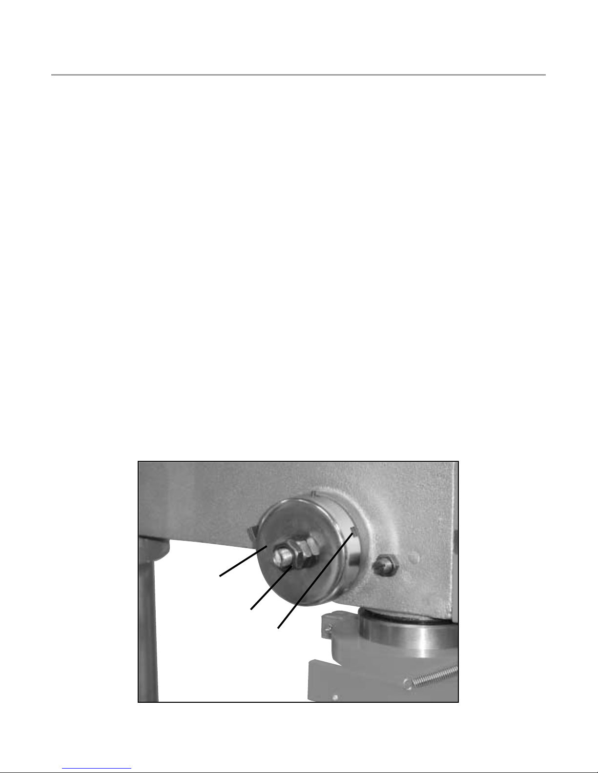
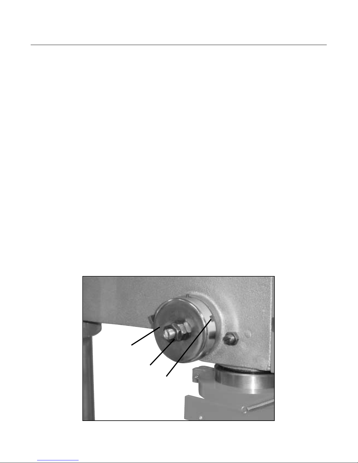
Place screwdriver in lower front notch (A) of spring cap (B) and hold it in place while loosening and removing nuts.
Carefully turn screwdriver counter clockwise and engage next notch. Fig. 15.
Tighten inner nut (C) with wrench. Do not over tighten, as this will restrict quill movement.
Move stop nuts to highest position and check tension while turning feed handle. If there is not enough tension on
spring, repeat steps A - D.
Check the quills while feeling for smooth and unrestricted movement, if movement is too tight, slightly loosen nuts
until unrestricted.
10
C
B
A
Page 11
Adjustments
Height Adjustment:
To adjust up or down, loosen the clamp bolt then adjust the table to your desired position by turning the table
bracket handle.
Tilting Adjustment: (If applicable)
Loosen the table bevel lock bolt with adjustable wrench. Tilt table to desired angle and retighten the bolt.
Swing 360 degrees:
Loosen clamp bolt then swing table to appropriate position and retighten clamp bolt.
Feed Depth Adjustment:
Depth control scale sleeve type loosen the clamp bolt and move to the desired depth then retighten the clamp
bolt.
Quill Spring Adjustment:
Move the stop nuts to lowest position and lock in place with wrench to prevent quill dropping while tensioning
spring.
Place screwdriver in lower front notch (A) of spring cap (B) and hold it in place while loosening and removing nuts.
Carefully turn screwdriver counter clockwise and engage next notch. Fig. 15.
Tighten inner nut (C) with wrench. Do not over tighten, as this will restrict quill movement.
Move stop nuts to highest position and check tension while turning feed handle. If there is not enough tension on
spring, repeat steps A - D.
Check the quills while feeling for smooth and unrestricted movement, if movement is too tight, slightly loosen nuts
until unrestricted.
10
C
B
A
Page 12

Maintenance
Lubrication
All of the BALL BEARINGS are packed with grease at the factory. They require no further lubrication.
Periodically lubricate the table elevation mechanism, the SPLINES (grooves) in the spindle, and the RACK
(teeth of the quill)
Mantenance
Frequently blow out any dust that may accumulate inside the motor.
A coat of automotive type paste wax applied to the table and column will help to keep th surfaces clean.
11
Noisy Operation Incorrect belt tension Adjust tension
Dry spindle Lubricate spindle
Loose spindle Checking tightness of retaining nut
on pulley, and tighten if necessary
Loose motor on pulley Tighten setscrews in pulleys
Drill bit burns Incorrect speed Change speed
Chips not coming out of hole Retract dril bit frequently to clear chips
Dull drill bit Resharpen drill bit
Feeding too slow Faster the speed
Not lubricated Lubricate drill bit
Drill leads off... Hard grain in wood or lengths of Resharpen drill bit correctly
hole not round cutting lips and/or angles not equal
Bent drill bit Replace drill bit
Wood splinters on underside No back up material under workpiece Use back up material
Workpiece turn loose Workpiece pinching dril bit or SUpport workpiece or clamp it
from hand excessive feed pressure
Improper belt tension Adjust tension
Drill bit binds in workpiece Workpiece pinching drill bit Support workpiece or clamp it
or excessive feed pressure
Improper belt tension Adjust tension
Excessive drill bit runout Bent drill bit Use a straight dril bit
or wobble
Worn spindle bearings Replace bearings
Drill bit not properly installed in chuck Install drill bit properly
Chuck not properly installed Install chuck properly
Quill returns too slow or fast Spring has improper tension Adjust spring tension
Chuck will not stay attached Dirty, grease or oil on the tapered Using a household detergent, clean the
to spindle, it falls off when inside surface of chuck or on the tapered surface of the chuck and
trying to install it spindles tapered surface spindle to remave all dirt, grease and
oil
Page 13
Wiring Dia grams
12
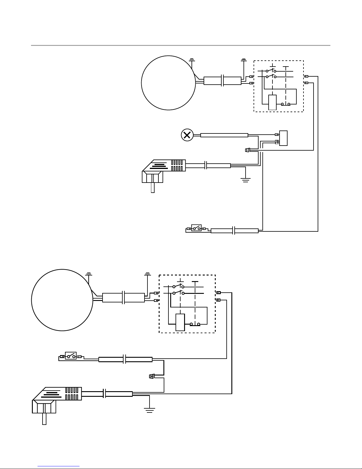
WIRING DIAGRAM MODELS WITH LIGHT
WIRING DIAGRAM -
MODELS WITHOUT LIGHT
MOTOR
N.V.R SWITCH
LIGHT
SWITCH
MICRO
SWITCH
MOTOR
N.V.R SWITCH
MICRO
SWITCH
Page 14
Par ts List
13
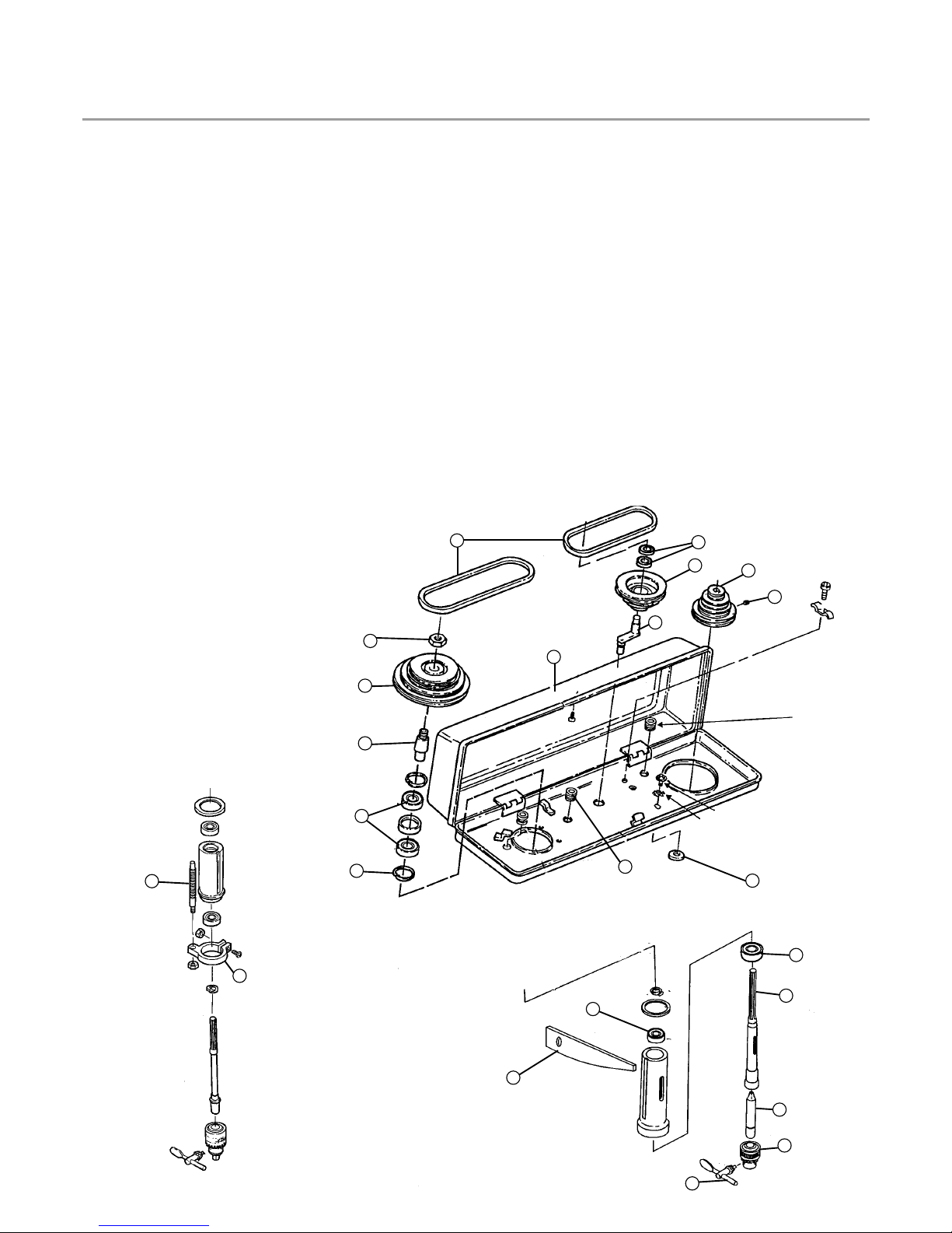
1 V-BELT
2 Guard w/labels
3 Retaining Spring
4 Ball Bearing x 2
5 Pulley Insert
6 Spindle Pulley
7 Spindle Pulley Nut
8 Motor Pulley
9 Screw Set Bolt
10 Centre Pulley
11 Pivot Idler
12 Ball Bearing
13 Ball Bearing
14 Collar Stop
15 Stop Rod
16 Ball Bearing
17 Shaft Spindle
18 Arbor
19 Chuck
20 Chuck Key
21 Key Drift
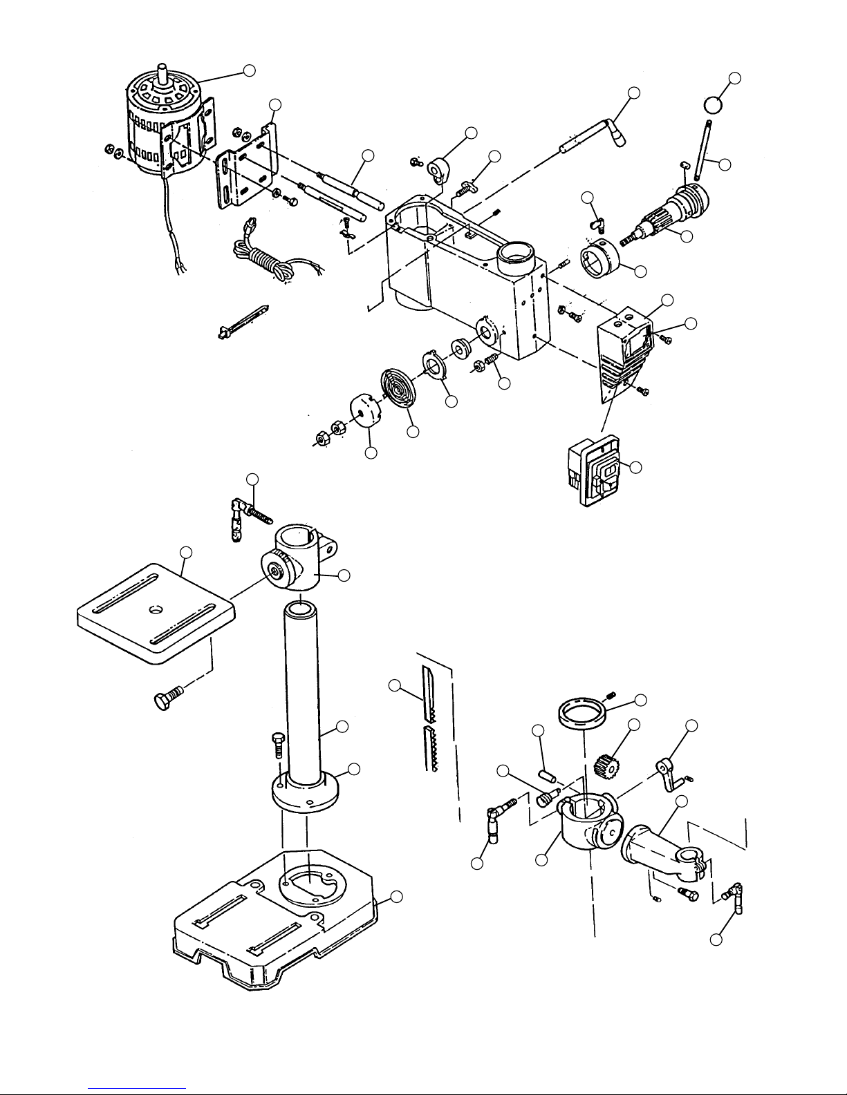
22 Base
23 Column
24 Rack
25 Table Support
26 Table
27 Column Clamp
28 Table Clamp
29 Column Support
30 Cranking Handle
31 Helical Gear
32 Worm Gear
33 Pin
34 Column Collar
35 Table Arm
36 Rubber Bush
37 Foam Washer
38 Motor
39 Motor Mount
40 Motor Support
41 Motor Adj. Knob
42 Belt Tension Handle
43 Handle Knob
44 Handle Rod
45 Shaft Pinion
46 Ring Depth w scale
47 Lock depth screw
48 Switch Box
49 NVR Switch
50 Light Switch
51 Set Screw
52 Spring Retainer
53 Tension Spring
54 Spring Cap
55 Adjusting Lever
1
2
11
12
8
9
10
6
7
4
5
36
3
21
13
16
17
18
19
20
15
14
37
}
B13-15 only
Page 15
14
38
39
40
55
41
42
43
44
47
45
46
48
50
49
51
52
53
54
27
26
25
24
32
23
29
22
27
25
28
34
33
31
30
35
Page 16

15
Page 17

Congratulations upon your new SIP purchase.
We thank you for having purchased SIP equipment
All SIP equipment has been designed, manufactured, tested and quality controlled to be complete and free of
manufacturing defects in order to provide long trouble free service.
In the unlikely event that difficulties should be experienced with your new purchase, please refer to the enclosed
instruction manual prior to contacting the SIP stockist from which the purchase was made. If the stockist is unable to
rectify the problem encountered, they will contact us directly on your behalf.
In order to solve your problem quickly, you will need to provide the following information.
1. Type and model of product purchased.
2. Proof of purchase indicating date and supplier.
3. Use for which product is tasked.
4. Problem encountered.
With this data we will always endeavour to find a prompt resolution.
ENVIRONMENT
We believe that the protection of the environment is of paramount importance, not only on a day to day basis but
also for our future generations. Please take the time to read this and make yourself aware of the environmental issues
related to the product which you have purchased so that you may also contribute towards the protection of our future.
1) Please dispose of the packaging for the product in a responsible manner. It is suitable for recycling. Help to
protect the environment, take the packaging to your local amenity tip and place it in the appropriate recycling bin.
2) If the product you have purchased requires oil changes to be carried out as part of the normal maintenance
schedule please ensure that the waste oil is disposed of in a responsible manner. Under Section 111 of the Water
Industry Act 1991 it is an offense to contaminate a drain or public sewer with oil. Most local amenity tips have oil
disposal facilities. Please use them.
3) When the product you have purchased has reached the end of its useful ser vice life or if you dispose of it for
another reason, give consideration to the fact that the product does contain recyclable materials. Most local amenity
tips have facilities to recycle these materials. Please use them.
Thank you for protecting the environment for yourself and future generations.
QUALITY AND ENVIRONMENT DEPARTMENT
SIP (INDUSTRIAL PRODUCTS) LTD
SIP (Industrial Products) Limited
Gelders Hall Road
Shepshed
Loughborough
Leicestershire
LE12 9NH
England
 Loading...