

Page 1

SIP Industrial Products Limited
Gelders Hall Road
Shepshed
Loughborough
Leicestershire
LE12 9NH
United Kingdom
SIP 31cc 4 Stroke Petrol Brush
Cuer with Grass Trimmer
For help or advice please contact
your distributor, or sip directly on:
Tel.: 01509 500400
Email:
or
08230
Please read and fully understand the instructions in this manual before
operation. Keep this manual safe for future reference.
1
Page 2

2
Page 3

3
INDEX
Page Content
4 Safety Symbols Used Throughout This Manual
4 - 6 Safety Instrucons
7 Guarantee
8 Technical Specicaon
9 Geng To Know Your Brush Cuer
10 Contents
11 - 18 Assembly Instrucons
19 - 24 Operang Instrucons - Starng
25 - 26 Operang Instrucons - Using / Controls
27 - 28 Maintenance
30 UK - Declaraon of Conformity
31 EU - Declaraon of Conformity
Page 4
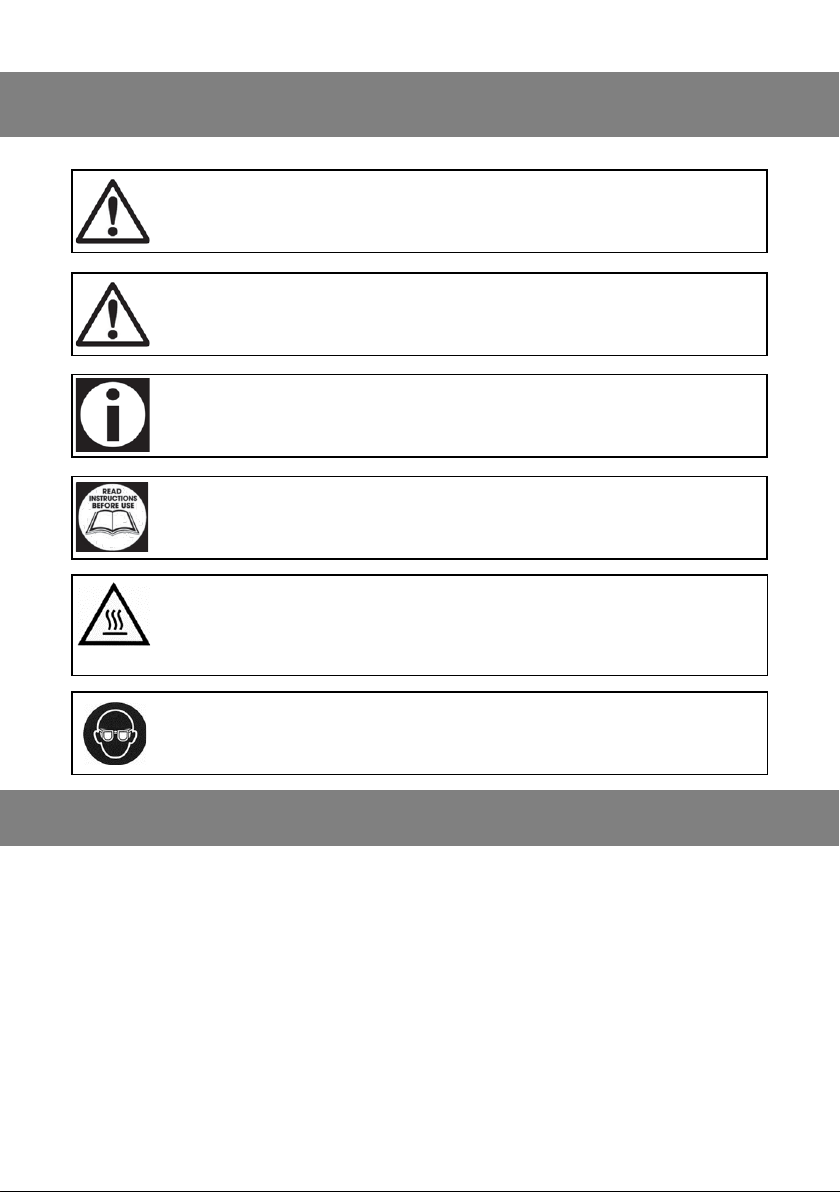
SAFETY INSTRUCTIONS USED THROUGHOUT THIS MANUAL
Danger / Cauon: Indicates risk of personal injury and / or the possibility
of damage.
Danger of Trapping: Risk of nger entrapment.
Note: Supplementary Informaon.
Important: Please read the following instrucons carefully, failure to do
so could lead to serious personal injury and / or damage to the Brush
Cuer.
Warning: This Brush Cuer contains surfaces which may reach a high
temperature during operaon.
Warning: Risk of injury or damage
SAFETY INSTRUCTIONS
When using your Brush Cuer, basic safety precauons should always be followed
to reduce the risk of re, personal injury and / or damage to the Brush Cuer. Read
all these instrucons before operang the Brush Cuer and save this user manual
for future reference.
SIP recommends that this Brush Cuer should not be modied or used for any
applicaon other than that for which it was designed; It was designed to be used
for clearing brush and trimming grass. If you are unsure of its relave applicaons
do not hesitate to contact us and we will be more than happy to advise you.
4
Page 5

SAFETY INSTRUCTIONS
KNOW YOUR BRUSH CUTTER:
Read and understand the owner's manual and labels axed to the Brush Cuer.
Learn its applicaons and limitaons, as well as the potenal hazards specic to it.
DO NOT USE THE BRUSH CUTTER IN DANGEROUS ENVIRONMENTS:
Do not use your Brush Cuer in damp or wet locaons, or expose it to rain / water.
KEEP CHILDREN AND UNTRAINED PERSONNEL AWAY FROM THE WORK AREA:
All visitors should be kept at a safe distance from the work area.
STAY ALERT: Always watch what you are doing and use common sense.
DRAIN FUEL AFTER USE:
Never leave the unit for a prolonged period of time without draining the fuel tank.
DO NOT RUN ENGINE WITHOUT ENGINE OIL:
Ensure that the engine oil level is checked before every use.
DRUGS, ALCOHOL AND MEDICATION:
Do not operate the Brush Cuer while under the inuence of drugs. alcohol, or any
medicaon that could aect your ability to use it correctly and safely.
AVOID DANGEROUS CONDITIONS:
Keep your work area clean and well lighted. Cluered areas invite injuries.
Do not use the Brush Cuer in wet or damp areas or expose it to rain.
Do not use it in areas where fumes from paint, solvents or ammable liquids pose a
potenal hazard.
INSPECT YOUR BRUSH CUTTER:
Check your Brush Cuer before turning it on. Keep guards in place and in working
order. Form a habit of checking to see that keys and adjusng wrenches are removed from tool area before turning it on.
Replace damaged, missing or failed parts before using it.
5
Page 6

6
SAFETY INSTRUCTIONS
WEAR APPROPRIATE CLOTHING:
Do not wear loose clothing, gloves, neck es or jewelry (rings, wrist watches). They
can be caught in moving parts.
Protecve electrically non conducve gloves and Steel Toe non-slip footwear are
recommended when working, Wear protecve hair covering to contain long hair,
prevenng it from geng caught in machinery.
PROTECT YOUR EYES AND FACE:
Any Brush Cuer may throw foreign objects into the eyes. This can cause permanent eye damage. Always wear safety goggles and/or face shield. Everyday eyeglasses have only impact resistant lenses. They are not safety glasses.
Page 7

7
This item is covered by a 24 month parts and labour warranty covering failure due
to manufacturers defects.
This does not cover failure due to misuse or operang the item outside the scope of
this manual - any claims deemed to be outside the scope of the warranty may be
subject to charges Including, but not limited to parts, labour and carriage costs.
Consumable items such as air lters, trimmer code, cung blades etc are not covered by the warranty.
Note: Proof of purchase will be required before any warranty can be
honoured.
GUARANTEE
Page 8

8
Engine Power 31cc Petrol Air Cooled 4 Stroke 1HP Euro V
Speed Range 2700 - 3400rpm
Fuel Tank Capacity 650ml
Cung Blade Ø 255 x 25.4 x 1.4mm
Cung Blade Max 7850rpm
Grass Trimmer Ø 430 x 2.4mm
Engine Oil Capacity 80ml
Engine Oil Type 10W40 (SIP Code 02419) / 15W40
Overall Dimensions
Length 1750mm
Width 735mm
Height 360mm
Weight GW9.8kg / NW7.5kg
Noise Level LwA LpA 94.67 / LwA 110dB - K=3
Vibraon 6.829m/s2 K=1.5m/s
2
TECHNICAL SPECIFICATION
Page 9
9
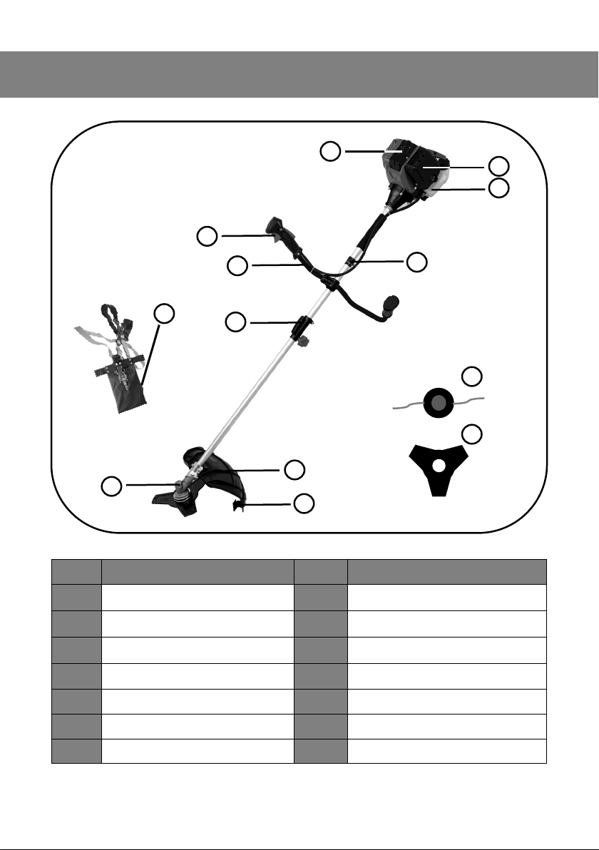
GETTING TO KNOW YOUR BRUSH CUTTER / GRASS TRIMMER
Item Descripon Item Descripon
1 Air Cleaner 8 Safety Guard
2 Fuel Tank 9 Cung Head
3 Engine 10 Line Trimmer
4 Harness Clip 11 Grass Trimming Aachment
5 Finger Trigger 12 Brush Cuer Aachment
6 Bull Horn Handle 13 Harness
7 Quick Connector
1
2
3
4
5
6
7
8
9
10
11
12
13
Page 10
10
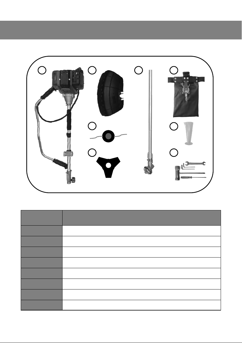
CONTENTS
Ref. No. Descripon
1 Base Unit
2 Safety Guard
3 Lower Sha
4 Harness
5 Grass Trimming Head
6 Fuel Cup
7 Brush Cung Head
8 Tool Kit
1
6
8
4
3
7
5
2
Page 11
11
ASSEMBLY INSTRUCTIONS
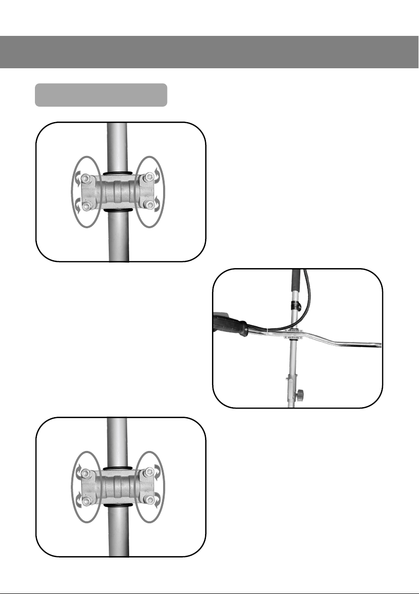
Bull-Horn Handle Assembly
• The Bull-Horn clamping plate
comes Pre-installed, this will
need removing before installaon.
• Remove the 4 x MG cap head
screws.
• Insert the Bull-Horn into the
clamp, ensuring the wiring harness is on top of the Drive Pole.
• The Bull-horns should be at 90°
perpendicular to the Drive Pole.
• Re-install the clamping plate and
insert the 4x M6 cap head screws
and nger ghten.
Page 12
ASSEMBLY INSTRUCTIONS
Hydraulic Ram Assembly
1
4
Important: Please read the following instrucons carefully, failure to do
so could lead to serious personal injury and / or damage to the Brush
Cuer.
Quick Connector Operaon
3
2
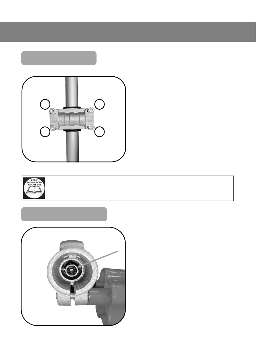
• Tighten the bolts following the
Torque Sequence (Shown Image
Le) .
• Ensure that the spline are correctly aligned during the assembly.
• Failure to do so will increase the
diculty of making the connecon., and lead to damage of the
splines.
12
Page 13
13
ASSEMBLY INSTRUCTIONS
Quick Connector Operaon Cont...
Important: Please read the following instrucons carefully, failure to do
so could lead to serious personal injury and / or damage to the Brush
Cuer.
Danger of Trapping: Risk of nger entrapment.
1
2
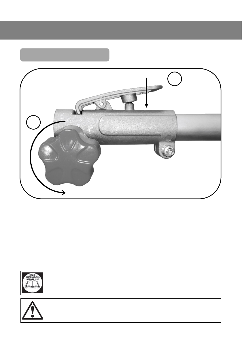
1: Unscrew the clamping screw by rotang it an-clockwise.
2: Press and hold the quick release lever. This allows the lower sha to t into
the main body.
Slight adjustment may be needed to the alignment splines when inserng.
Page 14
14
ASSEMBLY INSTRUCTIONS
4
3
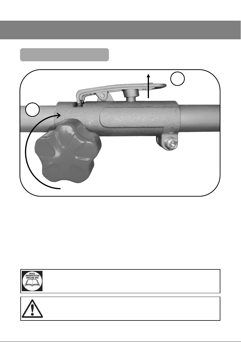
3: Once the lower sha has been inserted, rstly release the quick connector
lever, and rotate the lower sha slightly unl there is an audible clicking
sound.
4: Then rotate the locking screw clockwise, to ghten the clamp securely.
Important: Please read the following instrucons carefully, failure to do
so could lead to serious personal injury and / or damage to the Brush
Cuer.
Danger of Trapping: Risk of nger entrapment.
Quick Connector Operaon Cont...
Page 15
15
ASSEMBLY INSTRUCTIONS
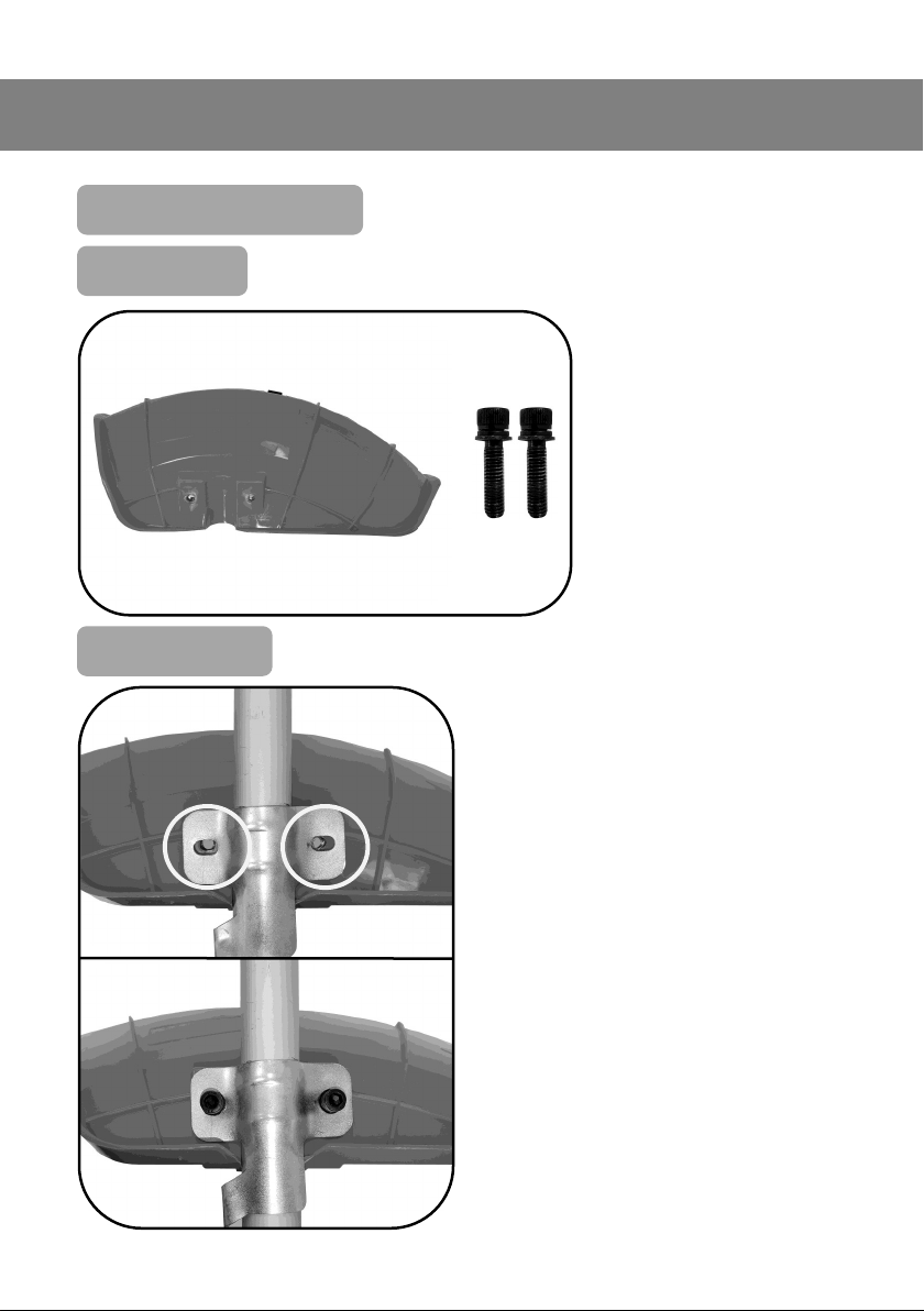
Installing the Safety Guard
Parts Needed
• 1 x Safety Guard
• 2 x M6 Cap-head
• Fit the guard with the head fac-
ing down.
• Align the two holes in the safety
guard, with the two holes in the
mounng bracket
(If there is any misalignment, the
bracket can be slightly adjust by
bending the tabs)
• Then insert the 2x M6 bolts and
ghten them.
Fing the Guard
Page 16
16
ASSEMBLY INSTRUCTIONS
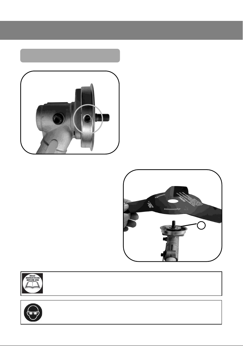
Installing The Brush Cung Blade
• To begin the installaon of the
brush cung blade, you need to
lock the spindle.
• This is achieved by inserng
5mm Hex key (Included in the
tool kit) into the Spindle Locking
Hole.
• Then remove the Nut and spacers that are installed.
• Place the blade on the raised
centre (A) of the gear sha facing up.
Warning: Risk of injury or damage
Important: Please read the following instrucons carefully, failure to do
so could lead to serious personal injury and / or damage to the Brush
Cuer.
A
Page 17
17
ASSEMBLY INSTRUCTIONS
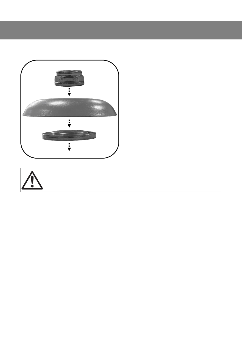
• Following the installaon of the
blade, install the spacers.
• The at washer should be installed rst, with the recess fac-
ing the blade
• Followed by the domed spacer.
• Once installed, t the Nut, and
ghten.
- Please note that the Nut has a
le handed thread -
Danger / Cauon: Ensure the 5mm Hex Key is removed immediately
aer installaon.
Page 18
18
ASSEMBLY INSTRUCTIONS
Installing The Grass Trimmer
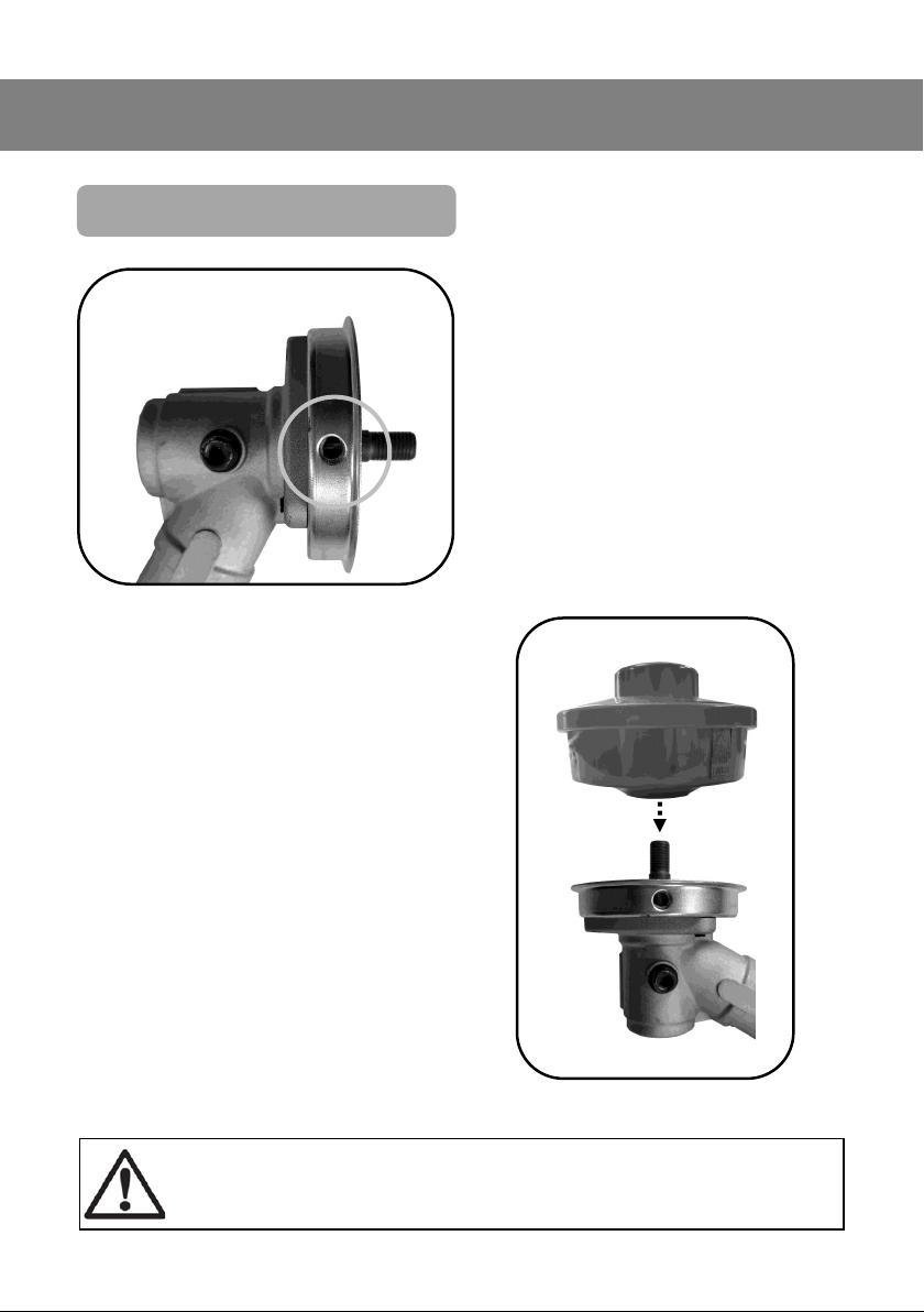
• To begin the installaon of the
Grass Trimmer, you need to lock
the spindle.
• This is achieved by inserng
5mm Hex key (Included in the
tool kit) into the Spindle Locking
Hole.
• Then remove the Nut and spacers that are installed.
• With all of the spacers removed,
install the grass trimming aachment.
• This is achieved by aligning the
threads and then spinning the
aachment, an-clockwise unl
it comes to a stop
• Once stopped, gently ghten it
into place.
Danger / Cauon: Ensure the 5mm Hex Key is removed immediately
aer installaon.
Page 19

19
OPERATING INSTRUCTIONS
1
2
3
4
5
6
7
Item Descripon Item Descripon
1 Air Cleaner 5 Spark Plug
2 Fuel Primer 6 Exhaust
3 Recoil Starter 7 Oil Filler
4 Fuel Filler
Key Components
Page 20
20
OPERATING INSTRUCTIONS
Before You Start
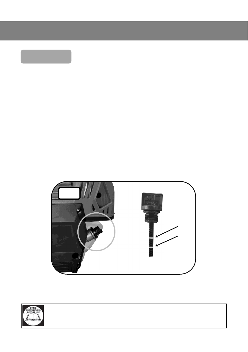
• Ensure that the oil level is correct;
This is done by seng the machine on a at and level surface
Remove the dipsck by rotang it an-clockwise.
Pull out and wipe any oil o with a clean cloth.
Re-insert the dipsck, but DO NOT screw in.
Remove the dipsck again, and check that the oil level sits between lines “A”
and “B” (Fig 1.)
Re-install the dipsck and ghten it into place by rotang it clockwise.
A
B
Fig 1.
Important: Please read the instrucons carefully, failure to do so could
lead to serious personal injury and / or damage to the Brush Cuer.
Page 21

21
OPERATING INSTRUCTIONS
Safety Checks
• Check the fuel level is sucient;
This is done by seng the machine on a at and level surface.
The fuel tank is translucent, so to check the fuel level to should look at the
side of the tank.
Fill to below the ller neck to allow an air gap, and keep leaks form the ller
cap to a minimum.
Always reinstate ller cap and ghten correctly for manoeuvring the product
Danger / Cauon: Clean all fuel spillages immediately, undiness could
lead to injury.
• Visual check of the product;
Check this all xings are ght, and secure.
Check for fuel and oil leaks.
Check for damage to casings.
Check for damage to the cung gear.
Important: Please read the instrucons carefully, failure to do so could
lead to serious personal injury and / or damage to the Brush Cuer.
Before You Start
Page 22
22
OPERATING INSTRUCTIONS
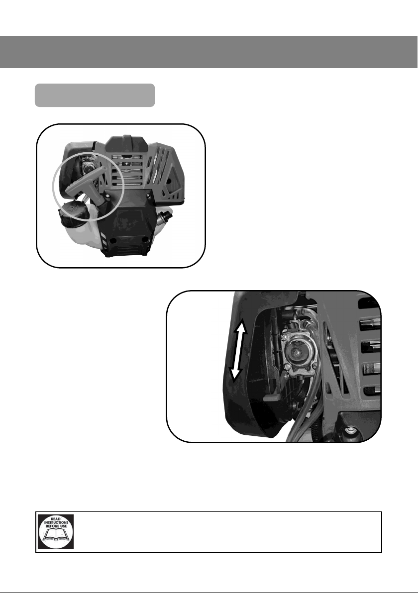
Starng The Brush Cuer
• Firstly pull the recoil starter handle slowly to its full extent.
This allows oil to be distributed
before starng the product .
Important: Please read the instrucons carefully, failure to do so could
lead to serious personal injury and / or damage to the Brush Cuer.
• Slide the choke lever
to the ON posion.
• This will need to stay
engaged unl the
engine has started.
Choke ON
Choke OFF
Page 23
23
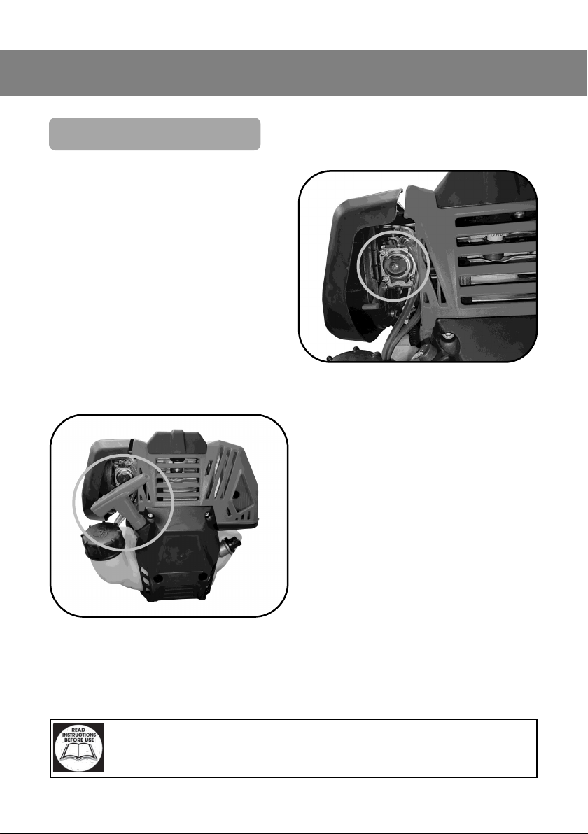
OPERATING INSTRUCTIONS
• On rst start up, or if the product
has been sing the priming fuel
bubble will be empty. To ll this
press and release the bubble,
unl the fuel has pulled through.
• Once the bubble has lled, press
the primer once . This primes the
engine with fuel ready for
starng
Starng The Brush Cuer Cont...
• Once the engine has been
primed, it is ready to start.
• Pull the recoil starter handle rapidly, to its full extent. And return
to its start posion.
This may need to be repeated up
several mes
Important: Please read the instrucons carefully, failure to do so could
lead to serious personal injury and / or damage to the Brush Cuer.
Page 24

OPERATING INSTRUCTIONS
Starng The Brush Cuer Cont...
Starng Your Brush Cuer Cont...
Choke OFF
• Once started, allow the engine to
run for 5 seconds.
• Then slowly move the choke lev-
el to the OFF posion.
If the engine starts to spluer,
move the choke slowly back to
the ON posion. Allow to run for
5 more seconds, then repeat the
process.
24
Page 25
OPERATING INSTRUCTIONS
Operang The Brush Cuer
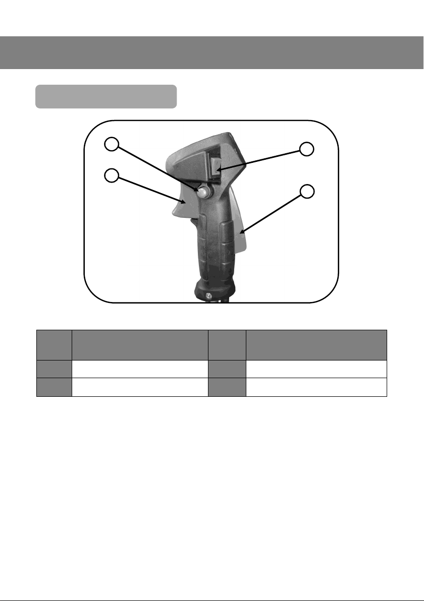
1
2
Item Descripon Item Descripon
3
4
1 Throle Lock 3 Kill Switch
2 Throle Trigger 4 Safety Latch
• To operate the trigger, you must rst depress the safety latch on the rear of
the handle, this will allow you to operate the throle trigger .
• The throle trigger is variable speed. The more the trigger is squeezed, the
faster the engine speed will increase.
• If you wish to use over a longer period of me, there is an opon to lock the
throle trigger.
• This is achieved by seng the speed you require with the throle trigger,
then pressing the throle lock buon.
25
Page 26

OPERATING INSTRUCTIONS
Operang The Brush Cuer Cont...
• To release the throle lock, slightly squeeze the throle lever, this will allow
the locking buon to spring out.
• To switch the machine o press the “Kill Switch” this will cut the machine o
immediately. Ensure the “Kill Switch” is returned to its run posion, before
aempng to restart the product.
26
Page 27

MAINTENANCE
Daily Maintenance
• Check engine oil
• Check general machine condion.
• Check for damage to cung heads
Monthly Maintenance
• Check Engine Oil
• Check fuel hoses
• Clean cung heads
• Clean Drive Mechanisms—Lubricate accordingly (32 grade oil)
Yearly Maintenance
• Change Engine Oil (15W40)
• Change Spark Plug (SIP Part No. PW37-00017)
Storage Maintenance
• Remove all fuel for from the fuel tank.
• Lubricate all moving parts with a suitable lubricang oil.
• Store back in the supplied packaging.
27
Page 28
MAINTENANCE
Changing the engine oil
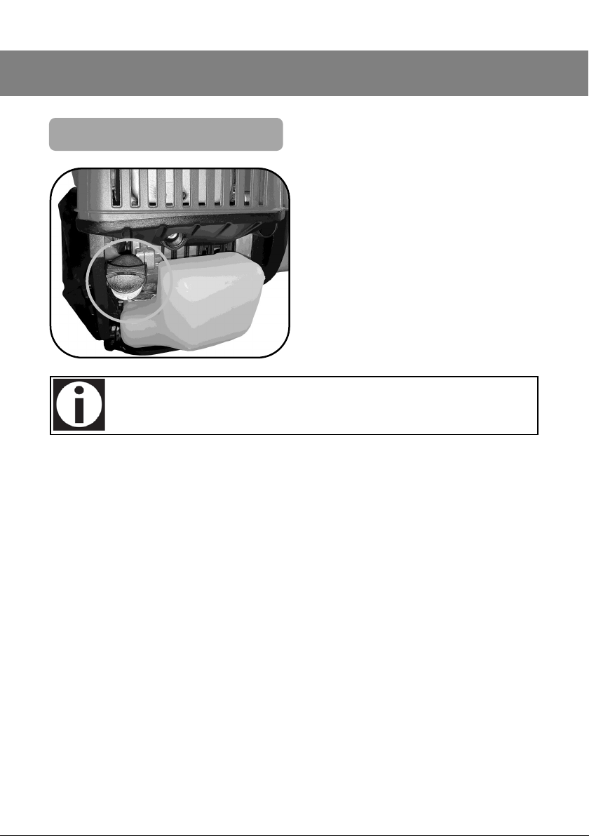
• To change the engine oil, you
must remove the dipsck, and
gently lt the unit so the oil
pours out of the ller.
The oil must be collected in a suitable container and disposed of
inline with local regulaons
• Once the old engine oil has been removed, it will need replacing.
• To do this carefully measure 80ml of 15W40 engine oil into a measuring just
• Then using a funnel pour through the ller neck
• Once the oil has seled in the engine (2-3Minutes) check the engine oil level
using the dipsck as shown on page 20
28
Page 29

29
NOTES
Page 30

UK - DECLARATION OF CONFORMITY
We
SIP (Industrial Products) Ltd
Gelders Hall Road
Shepshed
Loughborough
Leicestershire
LE12 9NH
England
As the manufacturer within the UK, England, Scotland & Wales, declare that the
SIP 31cc 4 Stroke Petrol Brush Cuer with Grass Trimmer: SIP Code 08230
Conforms to the requirements of the following regulaon(s), as indicated.
Supply of Machinery (Safety) Regulaons 2008
Electromagnec Completability Regulaons 2016
Noise Emissions in the Environment for Equipment for use Outdoors Regulaons 2001
Emissions From Non-road Machinery - 2016/1628/EC
Noise measurements have been made in accordance with the internal control of producon
(Schedule 45/Annex V). The declared noise values are as follows:
Guaranteed sound power level : 110dB(A)
And the relevant harmonised standard(s), including
BS EN ISO 11806-1:2022
BS EN ISO 14982:2009
BS EN ISO 22868:2011
Mr P. Ippaso - Managing Director
SIP (Industrial Products) Ltd
Date: 15/03/2024
30
Page 31

31
We
SIP (Machinery Europe) Ltd
ASM Chartered Accountants
First Floor Block One
Quayside Business Park
Dundalk
County Louth
Republic of Ireland
As the manufacturers authorised representave within the EC declare that the
SIP 31cc 4 Stroke Petrol Brush Cuer with Grass Trimmer: SIP Code 08230
Conforms to the requirements of the following direcve(s), as indicated.
2006/42/EC - Machinery Direcve
2014/30/EU - EMC Direcve
2000/14/EC - Noise Emission Direcve
2016/1628/EC - Emissions From Non-road Mobile Machinery
Noise measurements have been made in accordance with the internal control of producon
(Schedule 45/Annex V). The declared noise values are as follows:
Guaranteed sound power level: 110dB(A)
And the relevant harmonised standard(s), including
EN ISO 11806-1:2022
EN ISO 14982:2009
EN ISO 22868:2011
Mr P. Ippaso - Managing Director
SIP (Machinery Europe) Ltd
Date: 15/03/2024
EU - DECLARATION OF CONFORMITY
Page 32
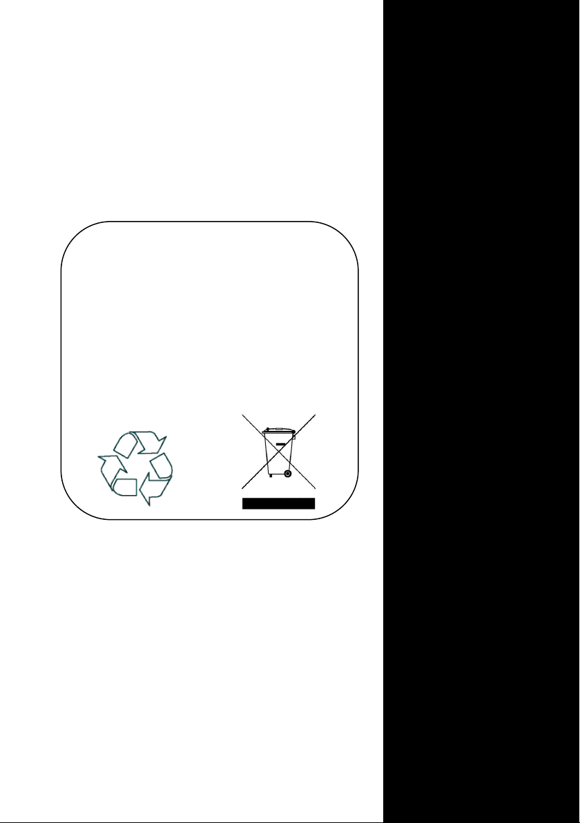
Please dispose of packaging for the product in a responsible
manner. It is suitable for recycling. Help to protect the environment, take the packaging to the local amenity tip and
place into the appropriate recycling bin.
Never dispose of electrical equipment or batteries in with
your domestic waste. If your supplier offers a disposal facility
please use it or alternatively use a recognised recycling agent.
This will allow the recycling of raw materials and help protect
the environment.
FOR HELP OR ADVICE ON THIS PRODUCT
PLEASE CONTACT YOUR DISTRIBUTOR,
OR SIP
DIRECTLY ON:
TEL: 01509 500400
EMAIL:
or
www.sip-group.com
NL13AUG2024 Revision 3
32
 Loading...