

Page 1
28
Ref: 230415
FOR HELP OR ADVICE ON THIS PRODUCT PLEASE CONTACT YOUR DISTRIBU-
TOR, OR SIP DIRECTLY ON:
TEL: 01509500400
EMAIL: [email protected] or [email protected]
www.sip-group.com
Please dispose of packaging for the product in a responsible
manner. It is suitable for recycling. Help to protect the
environment, take the packaging to the local amenity tip
and place into the appropriate recycling bin.
Never dispose of electrical equipment or batteries in with
your domestic waste. If your supplier offers a disposal facility please use it or alternatively use a recognised re-cycling
agent. This will allow the recycling of raw materials and help
protect the environment.
1
Professional Bench Grinder
07625, 07628 & 07645
Please read and fully understand the instructions in this manual
before operation. Keep this manual safe for future reference.
Page 2

2
27
Declaration of Conformity
We
SIP (Industrial Products) Ltd
Gelders Hall Road
Shepshed
Loughborough
Leicestershire
LE12 9NH
England
As the manufacturer's authorised representative within the EC
declare that the
6” Professional Bench Grinder - SIP Part No. 07625
8” Professional Bench Grinder - SIP Part No. 07628
10” Professional Bench Grinder - SIP Part No. 07645
Conforms to the requirements of the following directive(s), as indicated.
2006/42/EC Machinery Directive
2006/95/EC Low Voltage Directive
2004/108/EC EMC Directive
2002/95/EC RoHS Directive
And the relevant harmonised standard(s), including,
EN 55014-1:2006+A2:2011
EN 55014-2:1997+A2:2008
EN 61000-3-2:2006+A2:2009
EN 61000-3-3:2013
Signed: …………………………………...
Mr P. Ippaso - Managing Director - SIP (Industrial Products) Ltd
Date: 24/10/2014.
DECLARATION OF CONFORMITY
Page 3
26
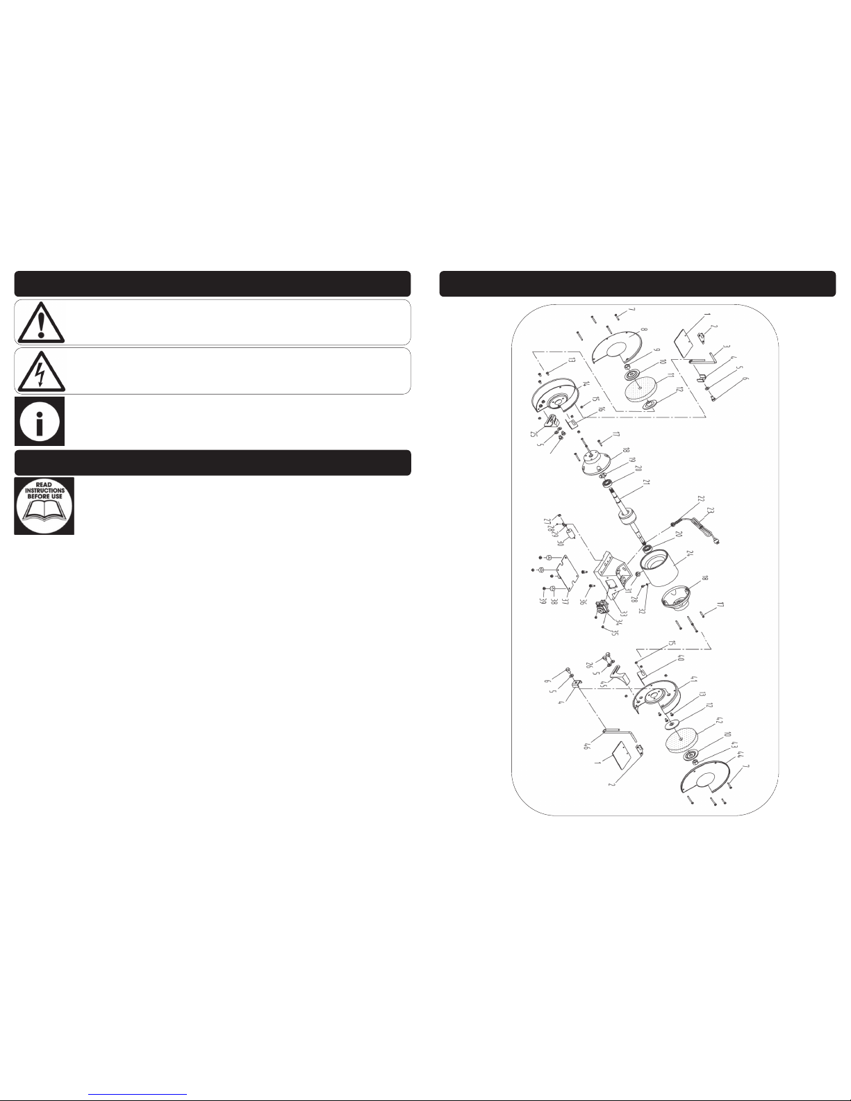
PARTS LIST 07645
Ref. No. Description Sip Part No. Ref. No. Description Sip Part No.
1. Eye shield WK05-00151 24. Stator WK05-00174
2. Eye shield holder WK05-00113 25. Left tool rest WK05-00175
3. Left eye shield arm WK05-00112 26. Bolt M8x10 WK05-00176
4. Bracket WK05-00111 27. Nut 8mm WK05-00132
5. Washer 8mm WK05-00159 28. Screw M4x8 WK05-00133
6. Bolt M8x14 WK05-00160 29. Capacitor support WK05-00131
7. Screw M5x62 WK05-00161 30. Capacitor 20mf WK05-00177
8. Left wheel cover WK05-00162 31. Mains lead grommet WK05-00125
9. Nut (16mm left) WK05-00142 32. Lock washer WK05-00179
10. Outer flange WK05-00163 33. Base WK05-00180
11.
Coarse wheel 36 grit
(250 x 25 x 20)
WK05-00164 34. NVR switch KJD12 WK05-00138
12. Inner flange WK05-00165 35. Screw M4x8 WK05-00127
13. Screw M5x10 WK05-00098 36. Bolt M8x22 WK05-00136
14. Left wheel guard WK05-00166 37. Base cover WK05-00181
15. Flanged nut 5mm WK05-00105 38. Rubber foot WK05-00134
16. Left spark arrestor WK05-00167 39. Screw M5x16 WK05-00137
17. Screw M5x20 WK05-00104 40. Right spark arrestor WK05-00182
18. End cap WK05-00168 41. Right wheel guard WK05-00183
19. Wave washer WK05-00169 42.
Fine wheel 60 grit
(250 x 25 x 20)
WK05-00184
20. Bearing 6204 WK05-00170 43. Nut (16mm right) WK05-00154
21. Rotor WK05-00171 44. Right wheel cover WK05-00185
22. Strain relief bush WK05-00129 45. Right tool rest WK05-00186
23. Mains lead WK05-00118 46. Right eye shield arm WK05-00120
3
CONTENTS
Page No. Description
4. Safety Symbols Used Throughout This Manual
4. Safety Instructions
8. Technical Specifications
9. Electrical Connection
10. Guarantee
10. Contents and Accessories
12. Getting To Know Your Grinder
13. Assembly Instructions
16. Operating Instructions
17. Maintenance
21. Exploded Drawing - 07625
22. Parts List - 07625
23. Exploded Drawing - 07628
24. Parts List - 07628
25. Exploded Drawing - 07645
26. Parts List - 07645
27. Declaration of Conformity
Page 4
4
When using electric tools / machines, basic safety precautions should always be followed to reduce the risk of fire, electric shock and personal injury.
Read all these instructions before operating the grinder and save this user manual for
future reference.
SIP recommends that this grinder should not be modified or used for any application
other than that for which it was designed.
It was designed to be bench mounted, for driving abrasive wheels for the purpose of
sharpening cutting tools such as chisels or drill bits. Alternatively it may be used to
roughly shape metal prior to welding or fitting etc.
If you are unsure of its relative applications do not hesitate to contact us and we will
be more than happy to advise you.
KNOW YOUR POWER TOOL: Read and understand the owner's manual and labels affixed to the grinder. Learn its applications and limitations, as well as the potential hazards specific to it.
KEEP WORK AREA CLEAN AND WELL LIT: Cluttered work benches and dark areas invite
accidents. Floors must not be slippery due to oil, water or metal dust etc.
DO NOT USE THE TOOL IN DANGEROUS ENVIRONMENTS: Do not use power tools in
damp or wet locations, or expose them to rain. Provide adequate space surrounding
the work area. Do not use in environments with a potentially explosive atmosphere.
KEEP CHILDREN AND UNTRAINED PERSONNEL AWAY FROM THE WORK AREA: All visitors
should be kept at a safe distance from the work area.
STORE TOOLS SAFELY WHEN THEY ARE NOT IN USE: All tools should be stored in a dry,
Danger / Caution: Indicates risk of personal injury and/or the possibility of
damage.
SAFETY SYMBOLS USED THROUGHOUT THIS MANUAL
Warning: Risk of electrical injury or damage!
Note: Supplementary information.
SAFETY INSTRUCTIONS
IMPORTANT: Please read the following instructions carefully, failure to do
so could lead to serious personal injury and / or damage to the bench
grinder.
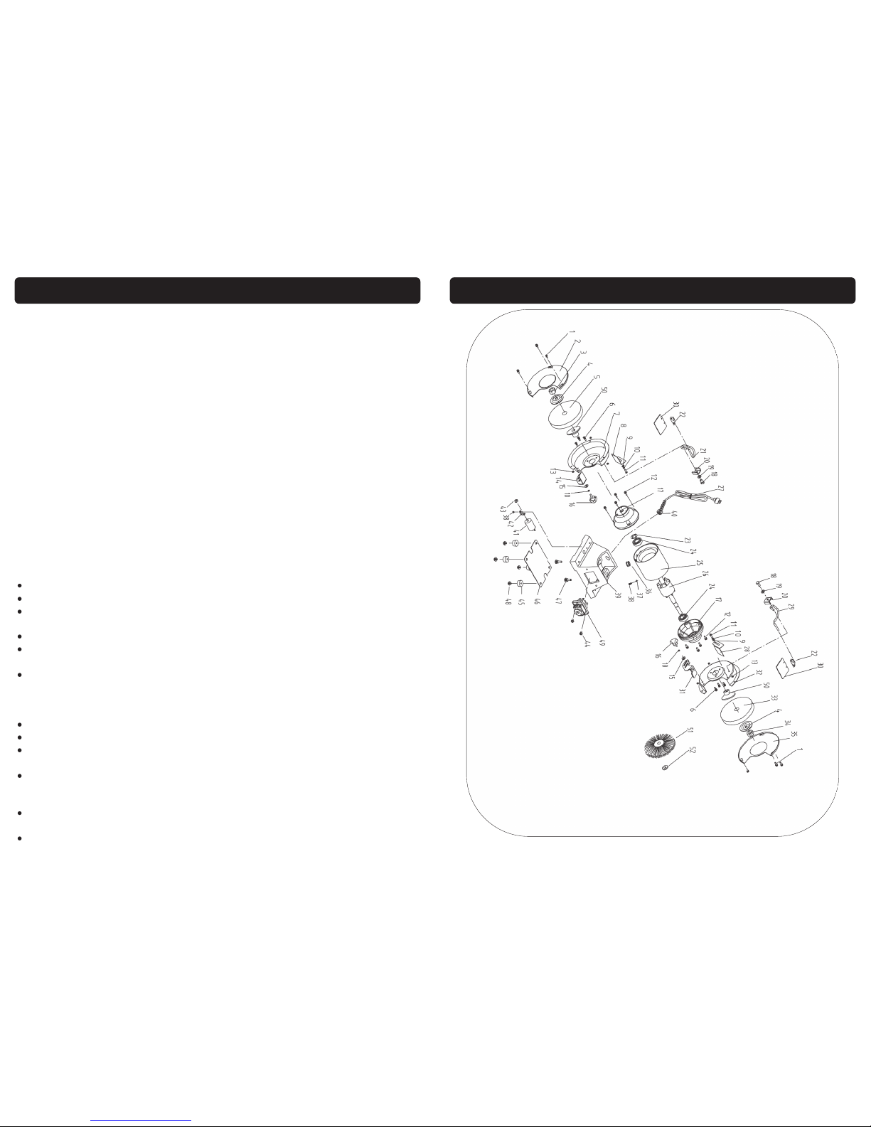
25
EXPLODED DRAWING 07645
Page 5
24
PARTS LIST 07628
Ref. No. Description Sip Part No. Ref. No. Description Sip Part No.
1. Screw M5x18 WK05-00095 27. Mains lead WK05-00118
2. Left wheel cover WK05-00141 28. Right spark arrestor WK05-00119
3. Nut (16mm left) WK05-00142 29. Right eye shield arm WK05-00120
4. Outer flange WK05-00143 30. Eye shield WK05-00151
5.
Coarse wheel 36 grit
(200 x 25 x 15.8)
WK05-00144 31. Right tool rest WK05-00122
6. Screw M5x10 WK05-00098 32. Right cover plate WK05-00152
7. Left wheel guard WK05-00145 33.
Fine wheel 60 grit
(200 x 25 x 15.8)
WK05-00153
8. Left spark arrestor WK05-00100 34. Nut (16mm right) WK05-00154
9. Washer 5mm WK05-00101 35. Right cover WK05-00155
10. Spring washer 5mm WK05-00102 36. Mains lead grommet WK05-00125
11. Screw M5x8 WK05-00103 37. Lock washer WK05-00126
12. Bolt M5x20 WK05-00104 38. Screw M4x8 WK05-00127
13. Nut 5mm WK05-00105 39. Base WK05-00128
14. Left tool rest WK05-00106 40. Strain relief bush WK05-00129
15. Washer 5mm (big) WK05-00107 41. Capacitor 10mf WK05-00188
16. Lock knob WK05-00187 42. Capacitor support WK05-00131
17. End cap WK05-00146 43. Nut 8mm WK05-00132
18. Bolt M6x14 WK05-00109 44. Screw M4x8 WK05-00133
19. Washer 6mm WK05-00110 45. Rubber foot WK05-00134
20. Bracket WK05-00111 46. Bottom cover WK05-00135
21. Left eye shield arm WK05-00112 47. Bolt M8x22 WK05-00136
22. Eye shield holder WK05-00113 48. Screw M5x16 WK05-00137
23. Spring washer WK05-00147 49. NVR switch KJD18 WK05-00138
24. Bearing WK05-00148 50. Inner flange WK05-00156
25. Stator WK05-00149 51. Wire wheel WK05-00157
26. Rotor WK05-00150 52. Washer for wire wheel WK05-00158
5
locked cupboard wherever possible and out of the reach of children.
WEAR THE CORRECT CLOTHING: Do not wear loose clothing, neckties, rings, bracelets,
or other jewellery, which may get caught in moving parts. Non-slip footwear is recommended. Wear protective hair covering to contain long hair. Roll long sleeves up
above the elbow.
USE SAFETY GOGGLES AND EAR PROTECTION ETC: Wear CE approved safety goggles
at all times, normal spectacles only have impact resistant lenses, they are NOT safety
glasses. A face or dust mask should be worn if the operation is dusty and ear protectors (plugs or muffs) should be worn, particularly during extended periods of operation.
PROTECT YOURSELF FROM ELECTRIC SHOCK: When working with power tools, avoid
contact with any earthed items (e.g. pipes, radiators, hobs and refrigerators, etc.). It is
advisable wherever possible to use an RCD (residual current device) at the mains
socket or supply board.
STAY ALERT: Always watch what you are doing and use common sense. Do not operate a grinder when you are tired or under the influence of alcohol or drugs.
DISCONNECT THE TOOL FROM THE MAINS SUPPLY: When not in use, before servicing
and when changing accessories such as wheels.
AVOID UNINTENTIONAL STARTING: Make sure the switch is in the OFF position before
connecting the grinder to the mains supply.
NEVER LEAVE THE TOOL RUNNING / CONNECTED WHILST UNATTENDED: Turn off the tool
and disconnect it from the mains supply between jobs. Do not leave the machine
until it comes to a complete stop.
DO NOT ABUSE THE MAINS LEAD: Never carry or move the grinder by the mains lead or
pull it to remove the plug from the mains socket. Keep the mains lead away from
heat, oil and sharp edges. If the mains lead is damaged, it must be replaced by the
manufacturer or its service agent or a similarly qualified person in order to avoid unwanted hazards.
CHECK FOR DAMAGED PARTS: Before every use of the grinder, a guard or other part
that is damaged should be carefully checked to determine that it will operate correctly and perform its intended function. Check for alignment of moving parts, free running of moving parts, breakage of parts, and any other conditions that may affect its
operation. A guard or other part that is damaged should be correctly repaired or replaced by an authorised service centre unless otherwise indicated in this instruction
manual. Have defective switches replaced by an authorised service agent. Do not
use the tool if the switch does not turn it on and off.
KEEP ALL GUARDS IN PLACE: And in full working order.
MAINTAIN TOOLS WITH CARE: Keep tools sharp and clean for the best and safest per-
formance. Follow instructions for lubricating and changing accessories. All extension
cables must be checked at regular intervals and replaced if damaged.
USE ONLY RECOMMENDED ACCESSORIES: Consult this user manual for recommended
accessories. Follow the instructions that accompany the accessories. The use of improper accessories may cause hazards and will invalidate any warranty you may
SAFETY INSTRUCTIONS...cont
Page 6
6
Use only the wheel flanges and nuts specified for this tool.
Before each use; Ensure that the wheel retaining nuts are fully secure.
Ensure that the grinder is securely bolted to a stable surface so it will not move
during operation.
Ensure that all keys and wrenches are removed before operating the grinder.
Ensure that the work-piece to be ground is clear of the grinding wheel before
the switch is turned on.
Before turning on the grinder, turn the wheel by hand to ensure nothing is catching, then turn the grinder on and let it run for a while; Watch for vibration or excessive wobble of the wheel that could indicate poor installation or a poorly
balanced wheel. Adjust or replace as necessary.
Allow the wheel to run up to full speed before grinding.
Stop operation immediately if you notice, or suspect anything abnormal.
Wait for the grinder to stop completely and remove the plug from the mains
supply before servicing or adjusting the grinder.
Be alert at all times, especially during repetitive, monotonous operations. Don't
be lulled into a false sense of security. Grinding wheels are extremely unforgiving.
Do not modify the grinder to do tasks other than those for which it was designed.
Ensure tool rests and eye shields are correctly adjusted.
SAFETY INSTRUCTIONS...cont
have.
REMOVE ADJUSTING KEYS AND WRENCHES: Form a habit of checking to see that keys
and adjusting wrenches are removed from the tool before every use.
DO NOT OVERREACH: Keep proper footing and balance at all times.
USE THE RIGHT TOOL: Do not use the tool or attachment to do a job for which it was
not designed.
DO NOT FORCE THE TOOL: It will do the job better and more safely at the rate which it
was designed.
DO NOT OPERATE POWER TOOLS IN EXPLOSIVE ATMOSPHERES: Do not use the grinder
in the presence of flammable liquids, gases, dust or other combustible sources. Grinding will create sparks which can ignite the dust or fumes.
DO NOT EXPOSE THE TOOL TO RAIN OR USE IT IN WET CONDITIONS: Water entering the
grinder will greatly increase the risk of electric shock.
KEEP THE MAINS LEAD WELL AWAY FROM THE CUTTING WHEEL: The mains lead should
be secured away from the cutting wheel at all times to avoid the risk of electric
shocks. Replace any damaged or tired looking leads immediately with the correct
rated cable.
ALWAYS CHECK THE WHEEL: Always inspect the wheel for cracks and general condition
before use as they could shatter at high speed causing injury to the operator and fel-
low work mates . If using an old wheel ensure that it hasn’t gone soft as the bond that
holds it together can go off over time.
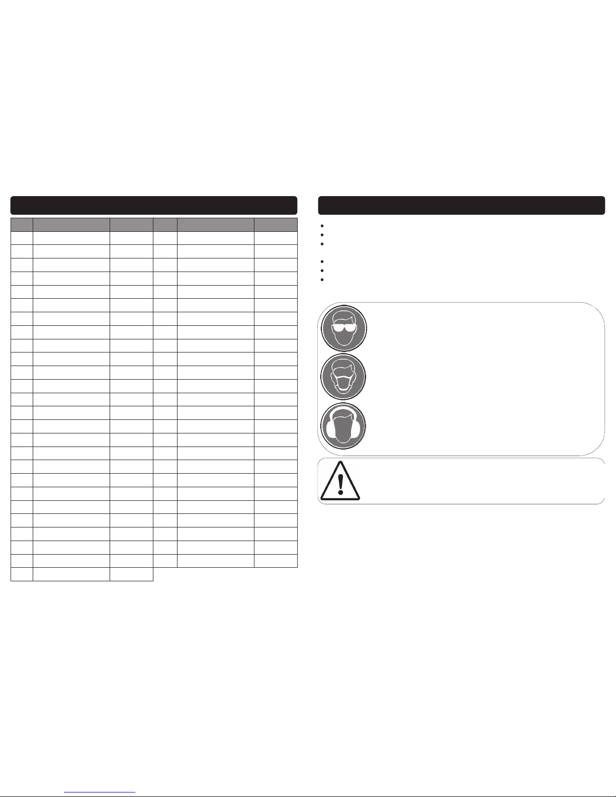
23
EXPLODED DRAWING 07628
Page 7
22
PARTS LIST 07625
Ref. No. Description Sip Part No. Ref. No. Description Sip Part No.
1. Screw M5x18 WK05-00095 27. Mains lead WK05-00118
2. Left wheel cover WK05-00096 28. Right spark arrestor WK05-00119
3. Nut (12mm left) WK05-00004 29. Right eye shield arm WK05-00120
4. Flange WK05-00097 30. Eye shield WK05-00121
5.
Coarse wheel 36 grit
(150 x 20 x12.7)
17638 31. Right tool rest WK05-00122
6. Screw M5x10 WK05-00098 32. Right cover plate WK05-00123
7. Left wheel guard WK05-00099 33.
Fine wheel 60 grit
(150 x 20 x 12.7)
17632
8. Left spark arrestor WK05-00100 34. Nut (12mm right) WK05-00006
9. Washer 5mm WK05-00101 35. Right cover WK05-00124
10. Spring washer 5mm WK05-00102 36. Mains lead grommet WK05-00125
11. Screw M5x8 WK05-00103 37. Lock washer WK05-00126
12. Bolt M5x20 WK05-00104 38. Screw M4x8 WK05-00127
13. Nut 5mm WK05-00105 39. Base WK05-00128
14. Left tool rest WK05-00106 40. Strain relief bush WK05-00129
15. Washer 5mm (big) WK05-00107 41. Capacitor 8mf WK05-00130
16. Lock knob WK05-00187 42. Capacitor support WK05-00131
17. End cap WK05-00108 43. Nut 8mm WK05-00132
18. Bolt M6x14 WK05-00109 44. Screw M4x8 WK05-00133
19. Washer 6mm WK05-00110 45. Rubber foot WK05-00134
20. Bracket WK05-00111 46. Bottom cover WK05-00135
21. Left eye shield arm WK05-00112 47. Bolt M8x22 WK05-00136
22. Eye shield holder WK05-00113 48. Screw M5x16 WK05-00137
23. Spring washer WK05-00114 49. NVR switch KJD18 WK05-00138
24. Bearing WK05-00115 50. Wire wheel WK05-00139
25. Stator WK05-00116 51. Washer for wire wheel WK05-00140
26. Rotor WK05-00117
7
Grinding produces particles which can become airborne and have
the potential to be highly toxic; always wear a face mask when operating the grinder.
When using the grinder always ensure the operator as well as those
in the area wear ear protection, particularly during periods of extended use.
SAFETY INSTRUCTIONS...cont
Caution: The warnings and cautions mentioned in this user manual can not
cover all possible conditions and situations that may occur. It must be understood by the operator that common sense and caution are factors which cannot be built into this product, but must be applied.
When using the grinder always ensure the operator as well as those
in the area wear eye protection.
Only use grinding wheels that are rated for the correct speed.
Do not overload the grinding wheel; stalling the machine will shorten its life.
After fitting new grinding wheel, leave machine running for at least one minute.
If the wheel is faulty it will break during this test period.
Stand to the side of the grinder during initial start up.
Use a wheel dresser only to remove burrs on the grinding wheel.
If the grinder is used in a place of work all rules and laws etc. relating to the use
of portable electrical appliances should be followed.
Page 8
8
TECHNICAL SPECIFICATIONS
Part No. 07625 07628 07645
Description 6” Bench Grinder 8” Bench Grinder 10” Bench Grinder
Input Voltage 230v 50Hz 230v 50Hz 230v 50Hz
Motor 370w 550w 750w
Wheel Speed 2850rpm 2850rpm 2850rpm
Duty Cycle S2, 30 minutes S2, 30 minutes S2, 30 minutes
Wheel Dimensions (mm) Ø150 x 20 x 12.7 (bore) Ø200 x 25 x 15.8 (bore) Ø250 x 25 x 20 (bore)
Protection IP23 IP23 IP23
Net Weight 6.29Kg 9.26Kg 24Kg
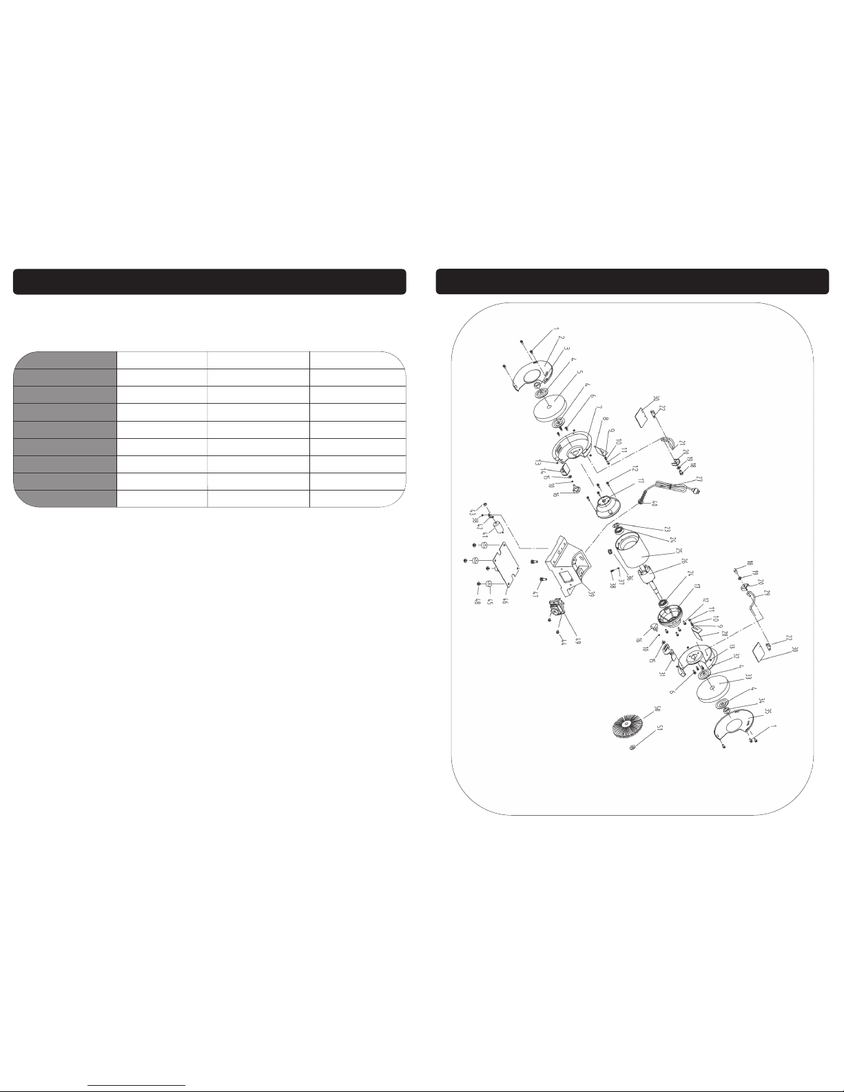
21
EXPLODED DRAWING 07625
Page 9
20
MAINTENANCE….cont
Hold the grinding wheel, or the opposite one, with one hand and turn the retaining nut clockwise for the left hand wheel, and anti clockwise for the right hand
wheel.
Note: Wear a protective glove to hold the grinding wheel whilst loosening
the retaining nut.
Remove the nut, outer flange and the grinding wheel.
Ensure that the shaft and flanges are clean and free from burrs etc.
Refit the flanges and wheel etc. as shown below.
Follow the instructions above, but in reverse to secure the new wheel and cover
etc.
Inner Flange Outer Flange
Shaft Wheel Nut
Blotter Blotter
Note: Do not over tighten the retaining nut; it needs to be tight enough to
hold the grinding wheel, but not so tight so that it damages the flanges.
9
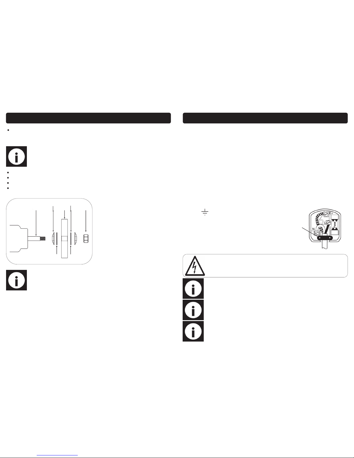
These grinders are fitted with a standard UK type 230v ~ plug. Before using the grinder
inspect the cable and plug to ensure that neither are damaged. If any damage is
visible have the grinder inspected / repaired by a suitably qualified person. If it is necessary to replace the plug a heavy duty impact resistant plug would be preferable.
The wires for the plug are coloured in the following way:
Yellow / green Earth
Blue Neutral
Brown Live
As the colours of the wires may not correspond with the markings in your plug, proceed as follows: The wire which is coloured blue, must be connected to the terminal
marked with N or coloured black. The wire which is coloured brown, must be connected to the terminal, which is marked L or coloured red. The wire which is coloured yellow / green should be connected to the terminal which is coloured the same or
marked.
Note: Always make sure the mains supply is of the correct voltage and the
correct fuse protection is used. In the event of replacing the fuse always
replace the fuse with the same value as the original.
Warning: Never connect live or neutral wires to the earth terminal of the
plug. Only fit an approved plug with the correct rated fuse. If in doubt
consult a qualified electrician.
Note: If an extension lead is required in order to reach the mains supply;
ensure that this too is rated for the correct voltage and fuse rating.
Note: The cross section of the extension lead should be checked so that it
is of sufficient size so as to reduce the chances of voltage drops.
ELECTRICAL CONNECTION
Always secure the wires in the plug terminal carefully and tightly.
Secure the cable in the cord grip carefully.
Cord Grip
Page 10
10
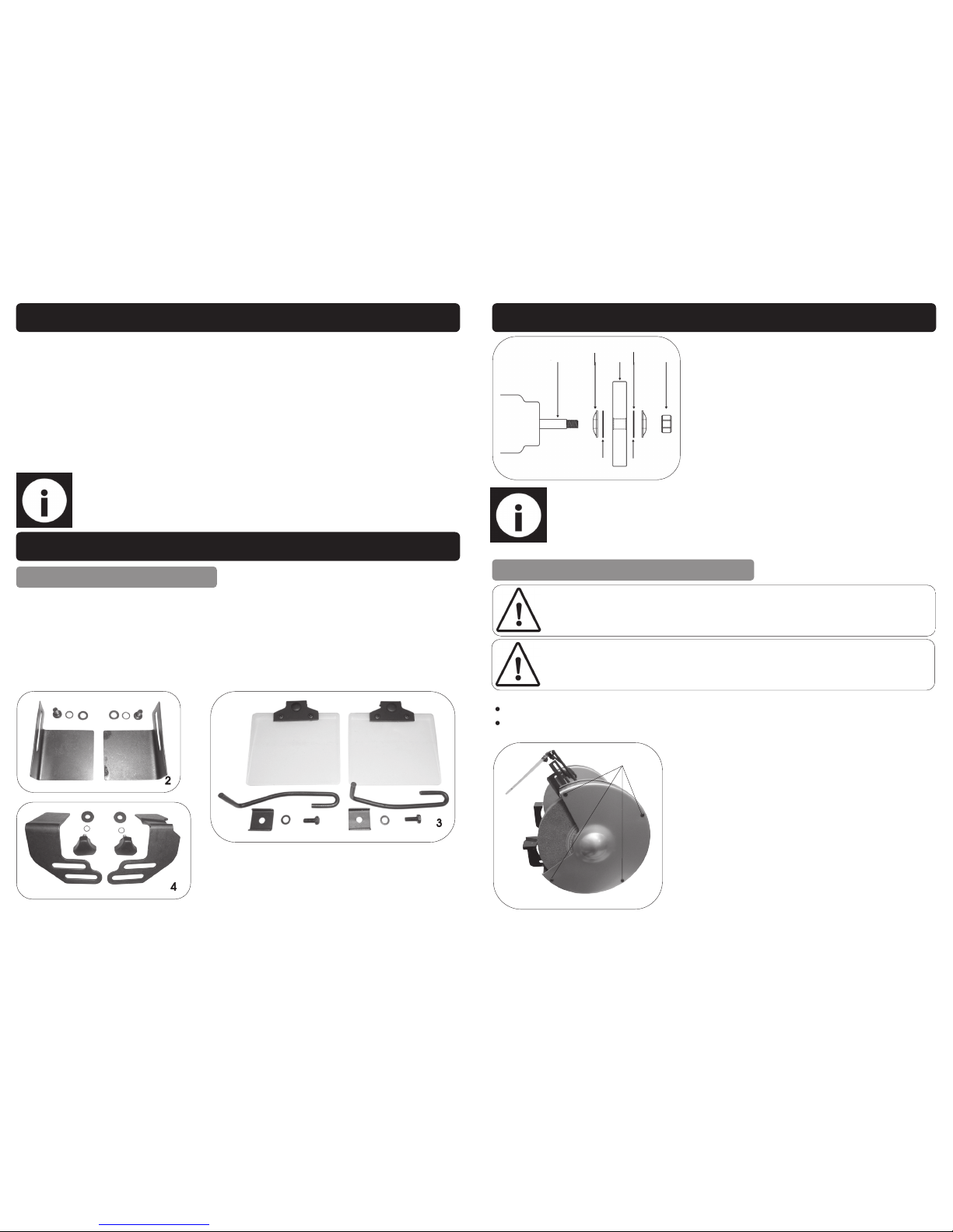
These SIP Bench Grinders are covered by a 12 month parts and labour warranty covering failure due to manufacturers defects. This does not cover failure due to misuse or
operating the grinders outside the scope of this manual - any claims deemed to be
outside the scope of the warranty may be subject to charges Including, but not limited to parts, labour and carriage costs. Consumable items such as grinding wheels
are not covered by the warranty.
In the unlikely event of warranty claims, contact your distributor as soon as possible.
Note: Proof of purchase will be required before any warranty can be honoured.
1. Bench Grinder c/w 2 x Grinding Wheels (not pictured).
2. Spark Arrestor x 2 (inc. fixings).
3. Eye Shield Assembly x 2 (1 x Left & 1x Right).
4. Tool Rest Assembly x 2 (inc. fixings).
5. Instruction Manual (not pictured).
GUARANTEE
CONTENTS AND ACCESSORIES
07625 & 07628
2
3
4
19
MAINTENANCE….cont
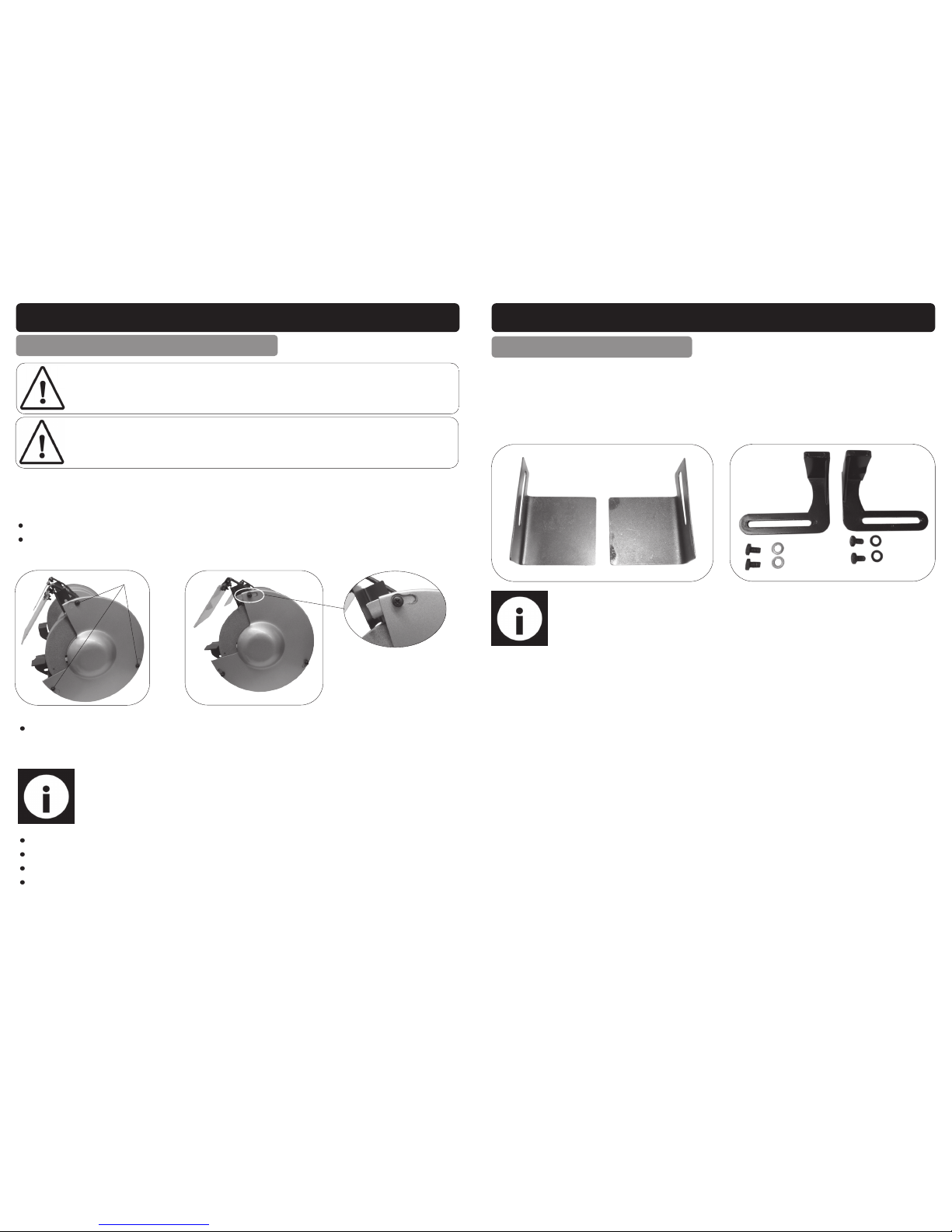
Inner Flange Outer Flange
Shaft Wheel Nut
Blotter Blotter
REPLACING THE GRINDING WHEELS 07645
Loosen and remove the 4 guard retaining screws and nuts (Fig. 14).
Remove the side guard.
Warning! Always ensure that the replacement wheel is of the correct size and rated
for the speed of the grinder as stated in the specifications.
Warning! Always ensure that a ’blotter’ (cardboard disc between the flange and the
grinding wheel) is fitted either side of the grinding wheel.
Screws
Fig. 14
Fig. 13
Note: Do not over tighten the retaining nut; it needs to be tight enough to
hold the grinding wheel, but not so tight so that it damages the flanges.
Page 11
18
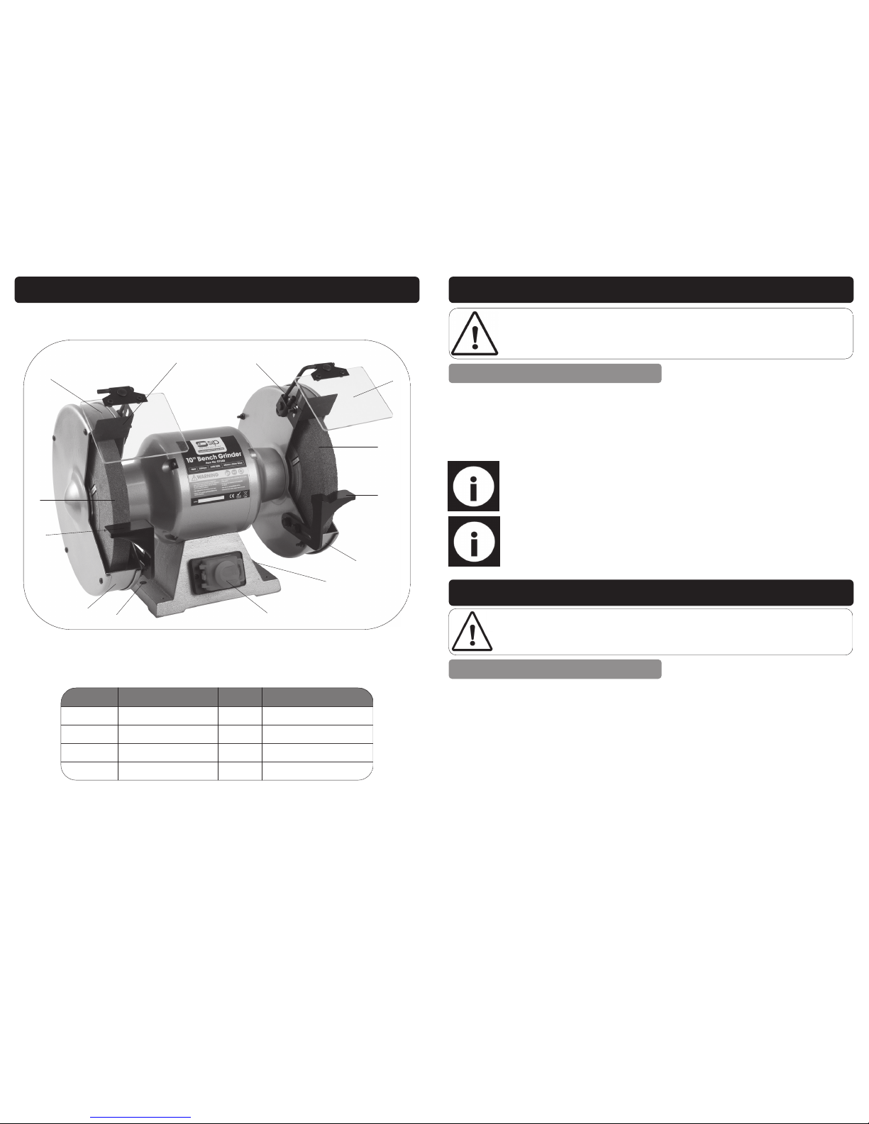
REPLACING THE GRINDING WHEELS 07625 & 28
Over time during normal usage the grinding wheels will become worn and need to be
replaced.
Loosen the 3 screws that hold the side cover on (Fig. 11).
Rotate the cover clockwise slightly so that the screw heads line up with the holes
on the side cover (Fig. 12); Remove the cover.
Hold the grinding wheel, or the opposite one, with one hand and turn the retaining nut clockwise for the left hand wheel, and anti clockwise for the right hand
wheel.
Warning! Always ensure that the replacement wheel is of the correct size
and rated for the speed of the grinder as stated in the specifications.
Warning! Always ensure that a ’blotter’ (cardboard disc between the flange
and the grinding wheel) is fitted either side of the grinding wheel.
Screws
Fig. 11
Fig. 12
Remove the nut, outer flange and the grinding wheel.
Ensure that the shaft and flanges are clean and free from burrs etc.
Refit the flanges and wheel etc. as shown on page 19, Fig. 13.
Follow the instructions above, but in reverse to secure the new wheel and cover
etc.
Note: Wear a protective glove to hold the grinding wheel whilst loosening
the retaining nut.
MAINTENANCE….cont
11
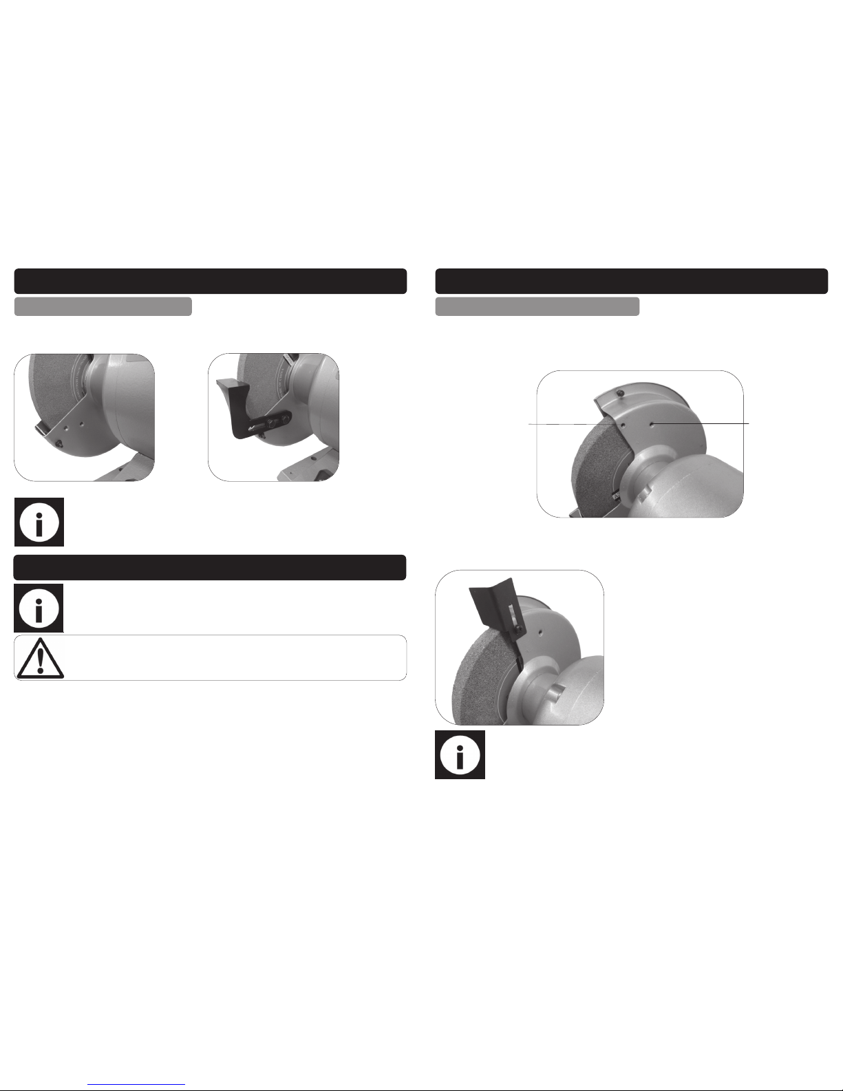
Note: If any parts are missing, or damaged, contact your distributor immediately for the missing parts to be replaced.
1. Bench Grinder c/w 2 x Grinding Wheels (not pictured).
2. Spark Arrestor x 2.
3. Eye Shield Assembly x 2 (1 x Left & 1x Right) see page 10.
4. Tool Rest Assembly x 2 (inc. fixings) see below.
5. Instruction Manual (not pictured).
07645
CONTENTS AND ACCESSORIES….cont
4
2
Page 12
12
GETTING TO KNOW YOUR BENCH GRINDER
Ref. No. Description Ref. No Description
1. On/Off Switch 5. Grinding Wheel
2. Mounting Hole 6. Eye Shield
3. Guard 7. Spark Arrestor
4. Tool Rest
3
5
6
7
6
7
1
4
5
3
2
4
2
17
OPERATING INSTRUCTIONS….cont
Warning! Always ensure that the grinder is bolted down onto a secure sur-
face prior to operation.
Note: Before starting the grinder, turn the wheels by hand making sure they
are clear of obstructions and that they turn freely. The tool rests and eye
shields should not touch the wheel.
The grinder is fitted with an NVR (No Volt Release) switch; This means that if power is cut
to the grinder it will not restart once the power is restored to the grinder.
The switch is located on the front of the grinder near the bottom.
To turn the grinder on, lift the cover and depress the green (I) switch.
to turn the grinder off, depress the red (0) button or close the cover.
SWITCHING THE GRINDER ON/OFF
Note: Turn on the grinder and allow it to reach full running speed before
starting to grind.
MAINTENANCE
Warning! Always ensure that the grinder is turned off and that the plug is disconnect-
ed from the mains supply before carrying out any adjustments, repairs or maintenance.
As the wheels wear, adjust the positions of the tool rests and spark arrestors; They
should be set so that they are as close to the grinding wheel as possible, but without
touching.
Regularly remove the wheel covers and clean out any dust and dirt.
The machine motor and bearings are sealed units and require no regular maintenance.
The eye shields should be cleaned regularly so that the operator has a clear view of
the work-piece and grinding wheel. Mild soap and water should be used; never use
solvents or similar products as they will damage the eye shield/s.
CLEANING AND ADJUSTMENTS
Page 13
16
Note: Before each operation; Turn the grinding wheel by hand to ensure
that the wheel turns freely without catching the tool rest etc.
Note: As with spark arrestor, the tool-rest should be set close to the grinding
wheel, without touching; turn the wheel by hand to ensure there is no contact.
OPERATING INSTRUCTIONS
Danger: Always ensure that the wheel retaining nut is fully tightened and
the wheel is secure before each operation.
Correct working practice:
Maintain a steady, moderate pressure on the work piece and keep it moving at an
even pace for smooth grinding.
Pressing too hard overheats the motor and prematurely wears down the grinding
wheels. The grinding wheel should rotate into the object, being sharpened. Keep a
tray filled with water and dip your work into it regularly to prevent overheating.
Do not use the side of the grinding wheel; This puts dangerous stress on the wheel.
When the wheel becomes loaded or ‘dull’, use an approved grinding wheel dresser
and dress the wheel face.
FITTING THE TOOL REST 07645
ASSEMBLY INSTRUCTIONS….cont
The tool rest fits to the inside of the guard towards the bottom (Fig. 9).
Use the supplied 2 x bolts and washers to secure in place (Fig. 10).
Fig. 9
Fig. 10
13
ASSEMBLY INSTRUCTIONS
FITTING THE SPARK ARRESTOR 07625 & 28
There are 2 holes on the inside of the guards (Fig. 1); A smaller one towards the front to
attach the spark arrestor, and a larger one towards the back to attach the eye shield.
Fit the spark arrestor and secure in place with the screw, spring washer and washer
(Fig. 2).
Note: The spark arrestor should be set close to the grinding wheel, without
touching it; turn the wheel by hand to ensure there is no contact.
Follow these instructions to fit the 2nd spark arrestor to the opposite side of the grinder
(07625 & 07628 only).
Eye Shield
Spark Arrestor
Fig. 1
Fig. 2
Page 14
14
Fig. 3
ASSEMBLY INSTRUCTIONS….cont
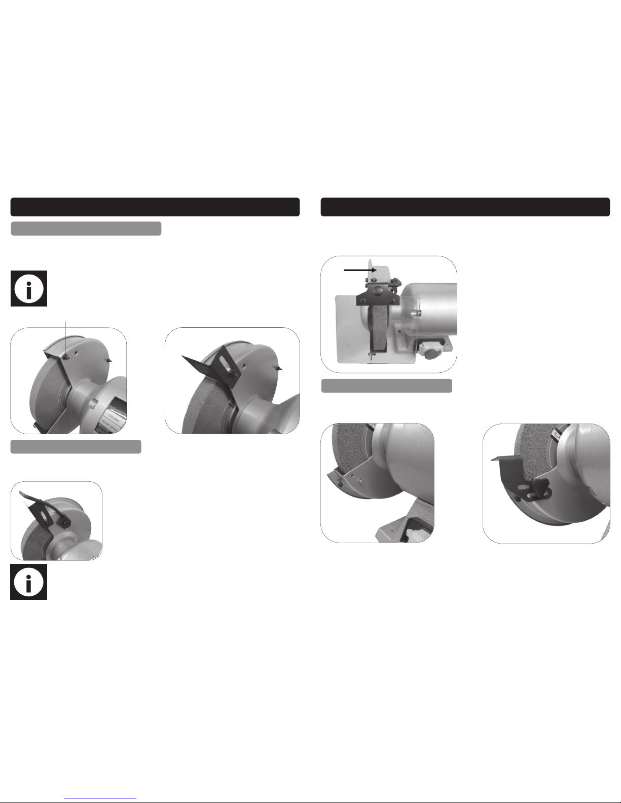
FITTING THE SPARK ARRESTOR 07645
Remove the nut from the guard retaining screw (Fig. 3).
Fit the spark arrestor over the screw and refit the nut (Fig. 4).
Tighten fully to secure.
Note: The spark arrestor should be set close to the grinding wheel, without
touching; turn the wheel by hand to ensure there is no contact.
Fig. 4
Guard Retaining Screw
FITTING THE EYE-SHIELD
Fit the eye-shield arm to the remaining hole (see fig. 5) and secure in place with the
bolt and retaining plate.
Fig. 5
Note: Take care not to over tighten the bolt as this will damage the guard;
It only needs to be tight enough to hold the eye shield in place whilst allowing the operator to easily change the angle.
15
FITTING THE TOOL REST 07625 & 28
ASSEMBLY INSTRUCTIONS….cont
Slide the eye-shield over the arm and secure in place by tightening the nut at the
back of the shield (fig. 6).
Follow these instructions to fit the 2nd eye-shield to the opposite side of the grinder.
Fig. 7
Follow these instructions to fit the 2nd tool-rest to the opposite side (07625 & 07628
only).
Fig. 6
The tool rest fits to the inside of the guard towards the bottom (Fig. 7).
Use the supplied thumbscrew, spring washer and washer to secure in place (Fig. 8).
Fig. 8
 Loading...