

Page 1
24
Please dispose of packaging for the product in a responsible
manner. It is suitable for recycling. Help to protect the
environment, take the packaging to the local amenity tip
and place into the appropriate recycling bin.
Never dispose of electrical equipment or batteries in with
your domestic waste. If your supplier offers a disposal facility please use it or alternatively use a recognised re-cycling
agent. This will allow the recycling of raw materials and help
protect the environment.
Ref:200116
FOR HELP OR ADVICE ON THIS PRODUCT PLEASE CONTACT YOUR DISTRIBUTOR,
OR SIP DIRECTLY ON:
TEL: 01509500400
EMAIL: [email protected] or [email protected]
www.sip-group.com
1
Please read and fully understand the instructions in this manual
before operation. Keep this manual safe for future reference.
05162
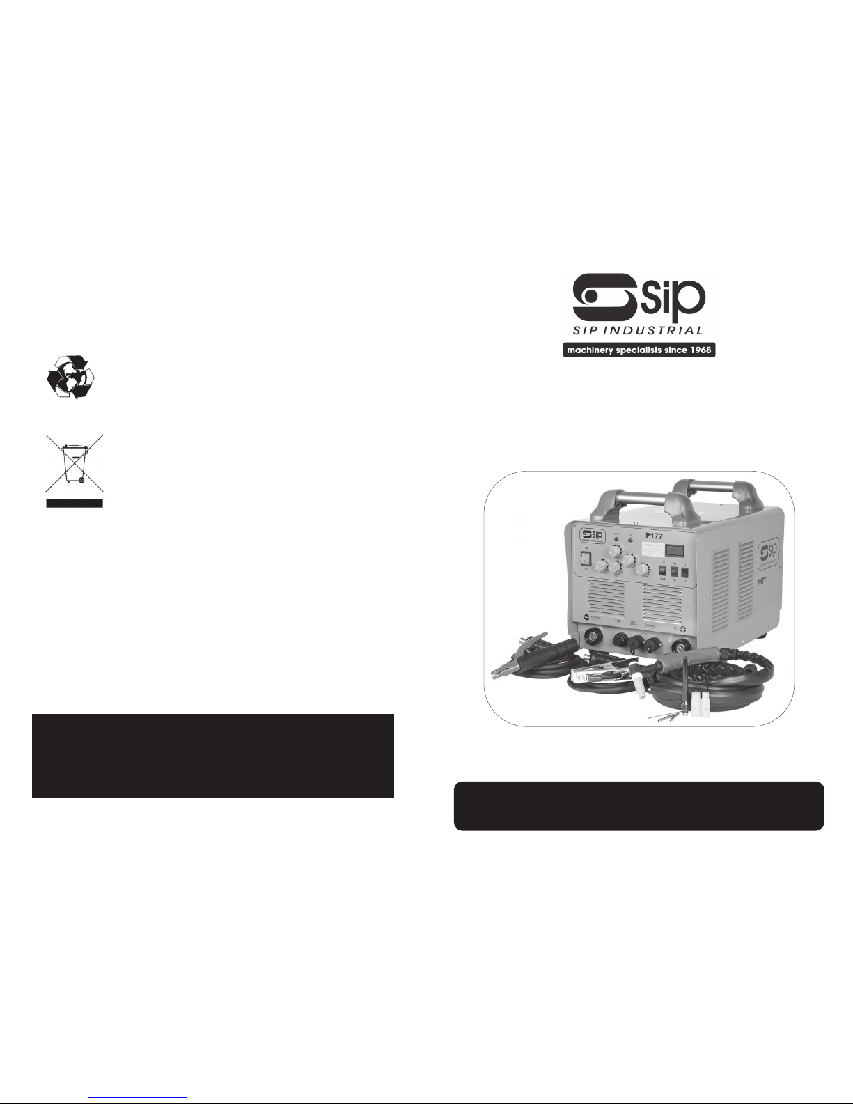
P177
AC/DC TIG Inverter
Page 2

2
23
GUARANTEE
Guarantee:
This welder is covered by a 24 month parts and labour warranty covering failure
due to manufacturers defects. This does not cover consumable items such as
torches, electrode holder and earth clamps. Failures due to misuse or operating
the machine outside the scope of this manual are also not covered.
In the unlikely event of warranty claims, contact your distributor as soon as possible.
Proof of purchase will be required before any warranty can be honoured.
Note: Proof of purchase will be required before any warranty can be
honoured.
Page 3

22
MAINTENANCE
1.Clear dust from machine at regular intervals use clean dry compressed air, if use in
a dirty environment the machine should be cleaned once a month, failure to clear
the dust may lead to machine failure and will invalidate the warranty.
2.Check all connections are clean and tight, if there is any oxidization clean the
connection with a mild abrasive or wire brush.
4.Check all the earth clamp and electrode in clean and in good condition of dirty
clean and if in poor condition replace.
5.Check the TIG torch it lead and consumables are in good condition, replace if
not.
6.If the machine is not to be used for a long time, store it in the original packing a
dry place.
3
CONTENTS
Page No. Description
3 Contents
4 Safety
5 Safety
6 Safety
7 Safety
8 Safety
9 Safety
10 Introduction
11 Introduction
12 Introduction
13 Technical Specification
14 Installation
15 Installation
15 Installation
16 Operating instructions ARC
17 Operating instructions ARC
18 Operating instructions TIG
19 Operating instructions TIG
20 Operating instructions TIG
21 Operating instructions TIG
22 Maintenance
23 Guarantee
Page 4
4
SAFETY
INTRODUCTION:
WE LEARN BY EXPERIENCE Learning safety through personal experience, like a child
touching a hot stove is harmful. wasteful. and unwise. Let the experience of others
teach you.
SAFE PRACTICES DEVELOPED FROM EXPERIENCE
In the use of welding described in this manual. Research, development, and field experience have evolved reliable equipment and safe installation, operation, and servicing practices. Accidents occur when equipment is improperly used or maintained.
The reason for these sole practices may not always be given. Some are based on
common sense, others may require technical volumes to explain, it is wiser to follow
the rules.
READ AND UNDERSTAND THESE SAFE PRACTICES
Before attempting to install, operate or service the equipment. Comply with these procedures as applicable to the particular equipment used and their instruction manuals,
for personal safety and for the safety of others.
FAILURE TO OBSERVE THESE SAFE PRACTICES
May cause serious injury or death. When safety becomes a habit, the equipment can
be used with confidence.
GENERAL:
The welding machine safe to operate under normal circumstances. If the unit is to be
used under unusual circumstances, e.g. in wet or damp conditions, on boats or oil
rigs, or in an elevated position. Then extra thought must be given to any possible hazard introduced by the situation.
ELECTRICAL:
A. DO NOT operate the machine with any of the panels removed.
B. DO NOT attempt any repairs unless you are a competent electrician.
C. Ensure that the machine is connected to the correct supply voltage through the
recommended fuse.
NB: This unit must be earthed.
D. DO NOT dismantle the torch without first switching off the machine.
ELECTRIC SHOCK
Either AC or’ DC voltages associated with the welding environment can cause severe
burns to the body or fatal shock. Severity of electrical shock is determined by the path
and amount of current through the body.
21
1.Set the mode switch on front of welder to TIG.
2.Set the AC/DC switch to DC.
3.Set the current switch to continuous.
4.Assemble the TIG torch using the correct size of electrode (see table below).
5.Connect the machine to the electrical supply and switch on.
6.Adjust the current control until the correct current is shown on the current display.
7.Set the post gas to 2S.
8.Perform a test weld and readjust the peak current control until the required weld is
achieved.
9.If the tungsten electrode becomes oxidized regrind the electrode and increase
the post gas time a little.
OPERATING INSTRUCTIONS TIG
DC TIG WELDING
1.Set the mode switch on front of welder to TIG.
2.Set the AC/DC switch to AC.
3.Set the current switch to continuous.
4.Assemble the TIG torch using the correct size of electrode (see table below).
5.Connect the machine to the electrical supply and switch on.
6.Adjust the current control until the correct current is shown on the current display.
7.Set the post gas to 2S.
8.Set the clean area width to 50%.
9.Perform a test weld and readjust the peak current control and clean area width
until the required weld is achieved.
10.If the tungsten electrode becomes oxidized regrind the electrode and increase
the post gas time a little.
AC TIG WELDING
Note: The following are basic instructions on how to operate the welder, to produce the best welds, training, practice and further reading
will be required.
Page 5

20
Welding
thickness mm
Tungsten Elec-
trode
diameter
mm
Welding cur-
rent Steel
A
Welding current
stainless steel
A
Welding current
Copper and
Copper alloys
A
0.5 1.0 30-60 15-30 30-40
1.0 1.6 50-70 50-70 70-60
1.5 1.6 90-110 60-90 100-130
2.0 1.6 100-130 80-100 130-150
3.0 2.4 120-140 100-130 130-180
4.0 2.4 150-190 130-170 170-250
6.00 3.2 200-300 200-300 200-300
Current settings for DC TIG welding
Welding
thickness mm
Tungsten Elec-
trode
diameter
mm
Welding current
A
0.5 1.0 15-20
1.0 1.6 40-50
1.5 1.6 50-80
2.0 1.6 90-110
3.0 2.4 120-300
4.0 2.4 180-220
5.0 3.2 250-300
Current settings for AC TIG welding Aluminium and its alloys
OPERATING INSTRUCTIONS TIG
5
SAFETY….cont
TO PROTECT AGAINST SHOCK
1.Keep body and clothing dry. Never work in a damp area without adequate insulation against electrical shock. Stay on a dry duck board, or rubber mat when dampness or sweat can not be avoided. Sweat, sea water. or moisture between body
and an electrically HOT part, or grounded metal reduces the body surface electrical resistance, enabling dangerous and possibly lethal currents to flow through the
body.
2.Never allow live metal parts to touch bare skin or any wet clothing, be sure gloves
are dry.
3.Before welding, check for continuity. Be sure the ground cable is connected to the
work piece as close to the welding areas as possible. Grounds connected to building frame work or other remote locations from the welding area reduce efficiency
and increase the potential electric shock hazard. Avoid the possibility of the welding
current passing through lifting chains, crane cables or various electric paths.
4.Frequently inspect cables for wear, cracks, and damage. IMMEDIATELY REPLACE
those with worn or damaged insulation to avoid a possibly lethal shock from bare
cables.
FIRE:
All inflammable materials must be removed from the area.
DO NOT weld containers which have held inflammable materials or gases.
Have a suitable fire extinguisher available close by.
GLARE AND BURNS:
The electric welding arc must not be observed with the naked eye. Always use a
welding mask or hand shield, ensure the mask/shield is fitted with correct shade of
filter for the welding process and current level.
Gloves should be worn to protect the hands from burns. Non-synthetic overalls with
buttons at neck and wrist, or similar clothing, should be worn. Greasy overalls should
not be worn. Wear suitable protective footwear.
COMPRESSED GAS:
Compressed air is potentially dangerous.
Refer to the relevant safety standards for safety guidelines.
Page 6
6
SAFETY….cont
VENTILATION:
Ventilation must be adequate to remove the smoke and fumes during welding. See
the relevant safety standard for acceptable levels.
FUMES:
Toxic gases may be given off when welding, especially if zinc or cadmium coated
materials are involved. Welding should be carried out in a well ventilated area, and
the operator should always be alert to fume build-up.
In small or confined places use a fume extractor.
VAPOURS:
Vapours of chlorinated solvents can form the toxic gas phosgene when exposed to
U.V radiation from an electric arc. All solvents, degreasers and potential sources of
these vapours must be removed from the welding area.
NB: IF IN DOUBT SEEK PROFESSIONAL ADVICE.
GENERAL PRECAUTIONS:
BURN PREVENTION
1. Wear Protective Clothing leather gauntlet gloves, hat, and high safety toe shoes.
Button shirt collar and pocket flaps, and wear cuff less trousers to avoid entry of
sparks and slag.
2. Wear Helmet with Safety Goggles or glasses with side shields underneath, appropriate filter lenses or plates (protected by clear cover glass). This is a MUST for welding
and chipping slag to protect the eyes from radiant energy and flying metal. Replace cover glass when broken. pitted, or spattered.
3. Avoid oily or greasy clothing. A spark may ignite them.
4. Hot metal such as electrode stubs and work pieces should never be handled without gloves.
5.Medical first aid and eye treatment. First aid facilities and a qualified first aid person
should be available for each shift unless medical facilities ore close by for immediate
treatment of flash burns to the eyes and skin.
Flammable hair preparations should not be used by persons intending to weld.
19
OPERATING INSTRUCTIONS PLASMA
OPERATING INSTRUCTIONS TIG
DC TIG -grind to a
point of 15-20 degrees.
Electrode preparation.
Chose the correct electrode type for the current type.
For DC you use Thoriated (red TIP), Ceriated (grey TIP) or Lathanated tungsten electrodes (black,gold,blue TIP).
For AC you use Pure tungsten (green tip), Zirconiated (white TIP) or Lathanated tungsten
electrodes (black,gold,blue TIP).
The tungsten should then be sharpened facing the grinding wheel. The tip should be
perfectly concentric in order to avoid arc deviations. It is best to regularly inspect the
tungsten to maintain peak condition.
AC TIG -grind the end tip
for electrodes smaller
than 2mm and chamfer
the tip to 45 degrees for
larger electrodes
Page 7

18
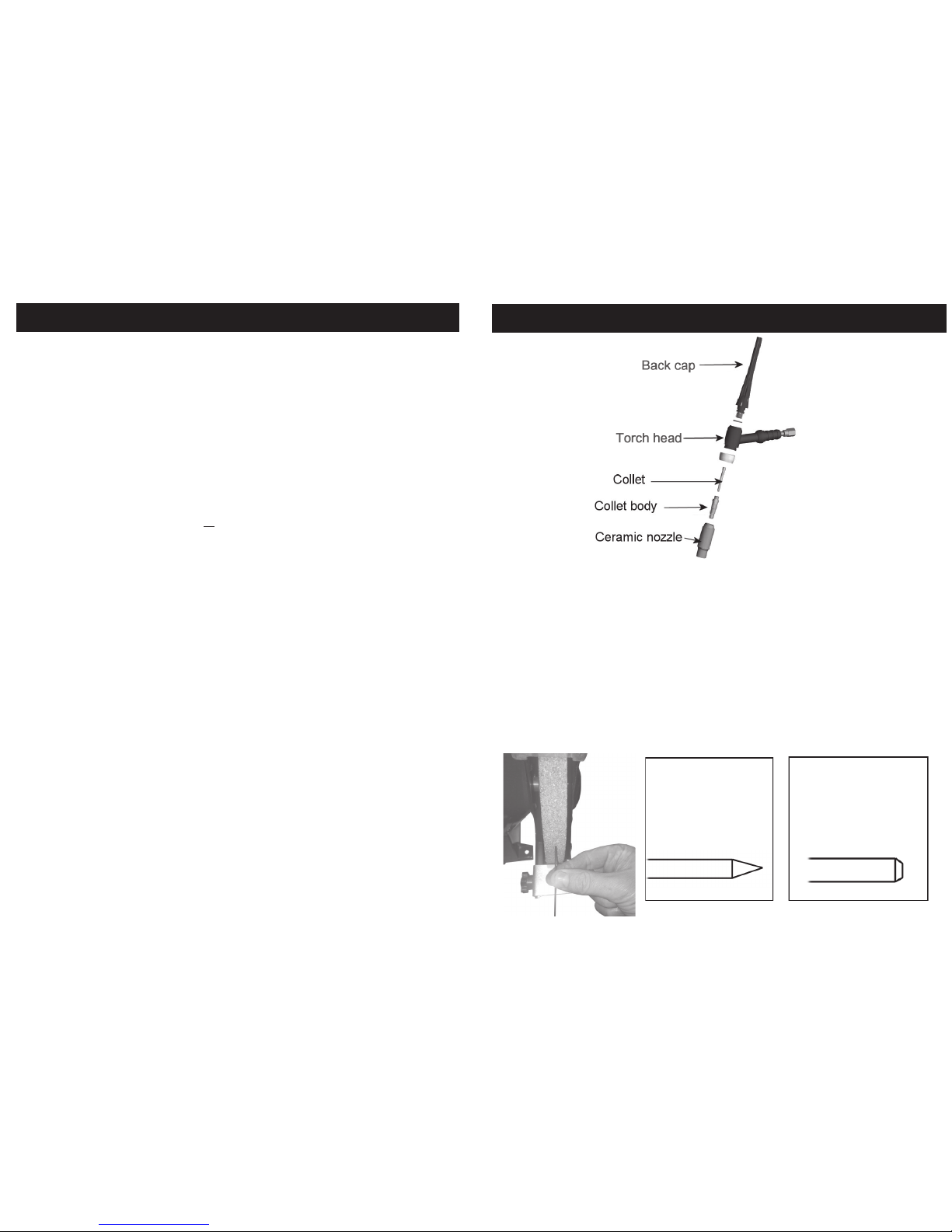
TIG torch assembly
1.Select the tungsten electrode to match current level polarity to be welded at.
2.Grind the end of the electrode to it’s required shape.
3.Select a collet body and collet that match the electrode size.
4.Select a ceramic nozzle for low power use a low number and high current a higher
number.
5.Select a back cap based on access to the weld area to fit shorter caps the electrode may need to be shortened.
6.Screw the collet body into the torch head.
7.Screw the ceramic nozzle on the collet body.
8.Insert the collet through the torch head into the collet body.
9.Push the electrode through into the collet until the point of the electrode is 10mm
past the end of the ceramic nozzle.
10.Screw the back cap onto the torch head but do not tighten.
11.Adjust the pointed end of the electrode so the distance from the point of the electrode to the end of the ceramic nozzle is approximately 3 times the diameter of the
electrode.
12.Tighten the back cap.
ALL TIG modes
You will need the following extra items
a.Regulator
b.Bottle of Argon Gas.
c.Tungsten welding electrode.
d.Filler rod.
At foot pedal control is available as an optional extra
1.Screw the TIG torch power/gas connection into the torch power socket on the front
of the P177, ensure the plastic insulator cover is fitted over the nut.
2.Connect the torch trigger connection to the trigger socket
3.Fit the earth return lead into the positive power socket.
4.Ensure the electrode lead is not attached to the P177.
5.Connect the gas connection on the rear of the P177 to the regulator on the argon
gas bottle, additional gas fittings and hose may be needed.
If you are using a foot pedal connect the 3 pin connector the remote control socket,
if you wish to trigger the welder using the foot pedal also fit the 2 pin connector into
the trigger socket instead of the torch trigger lead.
OPERATING INSTRUCTIONS TIG
7
SAFETY….cont
FIRE AND EXPLOSION PREVENTION:
1.Causes of fire, and explosion are: combustibles reached by the arc, flame, flying
sparks, hot slag or heated material, misuse of compressed gases and cylinders, and
short circuits. BE AWARE THAT: flying sparks or falling slag can pass through cracks
along pipes, through windows or doors, and through wall or floor openings and out
of sight of the operator. Sparks and slag can fly up-to 10 metres.
2.Keep equipment clean and operable, free of oil, grease and (in electrical parts) of
metallic particles that can cause short circuits.
3.If combustibles are in the area. DO NOT weld , move the work if practical to an area
free of combustibles. Avoid paint spray rooms, dip tanks, storage areas, ventilators. If
the work can not be moved, move combustibles at least 35 feet away out of reach
of sparks and heat, or protect against ignition with suitable and snug fitting, fireresistant covers or shields.
4.Walls touching combustibles on opposite sides should not be welded on. Walls, ceilings and floor near the work area should be protected by heat resistant covers or
shields.
5.A fire watcher must be standing by with suitable fire extinguishing equipment during
and for some time after welding:
a.Appreciable combustibles (Including building construction) are within 10 metres.
b.Appreciable combustibles are further than 35 feet but can be ignited by sparks.
c.Openings (concealed or visible) in floors or walls within 10 metres may expose com-
bustibles to sparks.
d.Combustibles adjacent to walls, ceilings, roofs or metal partitions can be ignited by
radiant or conducted heat.
6.After work is done, check that area is free of sparks, glowing embers, and flames.
7.An empty container that held combustibles, or that can produce flammable or toxic vapours when heated, must never be welded on, unless container has first been
cleaned as described in AWS Standard A6.0 listed 3 in Standards Index. This includes
a thorough steam or caustic cleaning (or a solvent or water washing, depending on
the combustible’s solubility) followed by purging and inserting with nitrogen or carbon
dioxide, and using protective equipment as recommended in A6.0 Water filling just
below working level may substitute for inerting.
8.A container with unknown contents should be cleaned (see paragraph above), DO
NOT depend on sense of smell or sight to determine if it is safe to weld.
9.Hollow items must be vented before welding or they can explode.
10.Explosive atmosphere, never weld where the air may contain flammable dust, gas
or liquid vapours (such as petrol).
Page 8
8
SAFETY….cont
HOSE
1.Use ferrules or clamps designed for the hose (not ordinary wire or other substitute) as
binding to connect hoses to fittings.
2.No copper tubing splices, use only standard brass fittings to splice hose.
3.Avoid long runs to prevent kinks and abuse, suspend the hose off the ground to
keep it from being ran over, stepped on, or otherwise damaged.
4.Coil excess hose to prevent kinks and tangles.
5.Protect hose from damage by sharp edges, sparks, slag and open flames.
6.Examine hose regularly for leaks, wear and loose connections. Immerse pressured
hose in water bubbles indicate leaks.
7.Repair leaking or work hose by cutting area out and splicing. DO NOT use tape.
8.Never leave equipment unattended. When not welding, turn off the equipment. DO
NOT coil or loop the welding torch or earth cable around parts of the body, turn the
unit off when left unattended.
Flash goggles with side shields MUST be worn under the helmet to give some protection to the eyes should the helmet not be lowered over the face before an arc is
struck. Prevent looking at the arc momentarily with unprotected eyes (particularly at
high intensity) as the arc can cause a retinal burn that may leave a permanent dark
area in the field of vision.
PROTECTION OF NEARBY PERSONNEL
1.Warn bystanders not to watch the arc and not to expose themselves to the weldingarc rays or to hot metal.
2.Keep children away while welding, they are not aware that looking at an arc ray
can cause serious eye damage.
3.Protect other nearby personnel from arc rays and hot sparks with a suitable nonflammable partition.
4.Bystanders should also wear safety glasses or goggles.
TOXIC PREVENTION
1.Adequate ventilation, severe discomfort, illness or death can result from fumes, vapours, heat, or oxygen enrichment or depletion that welding may produce, prevent
them with adequate ventilation. NEVER ventilate with oxygen.
2.Lead, cadmium, zinc, mercury and beryllium bearing and similar materials, when
welded may produce harmful concentrations of toxic fumes. Adequate local exhaust ventilation must be used., or each person in the area as well as the operator
should wear an air-supplied respirator, for beryllium, both must be used.
3.Metals coated with or containing materials that emit toxic fumes should not be
heated unless coating is removed from the work surface. The area should be well
ventilated, or the operator should wear an air supplied respirator.
4.Work in a confined space only while it is being ventilated and if necessary, while
17
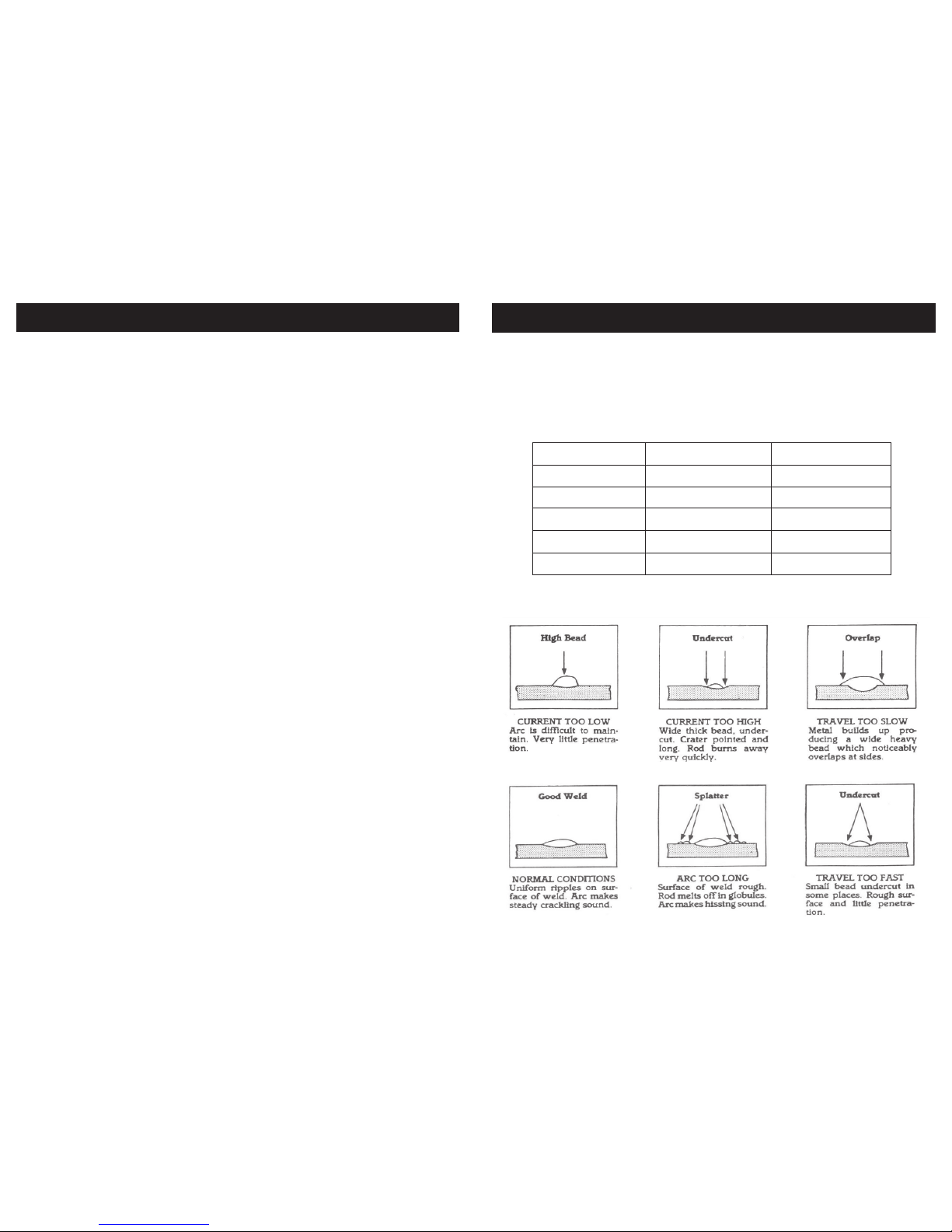
Electrode size mm Material thickness mm Welding current A
1.6 1-1.6 25-40
2.0 1.6-2.6 40-70
2.5 2.6-4.0 60-100
3.25 3.0-5.0 80-130
4.0 5.0-7.0 130-170
ARC welding beads
Current setting for ARC welding
These settings are for E6013 electrodes, for other types of electrode consult the technical data sheets.
OPERATING INSTRUCTIONS ARC
Page 9
16
INSTALLATION….cont
ARC (MMA welding) mode
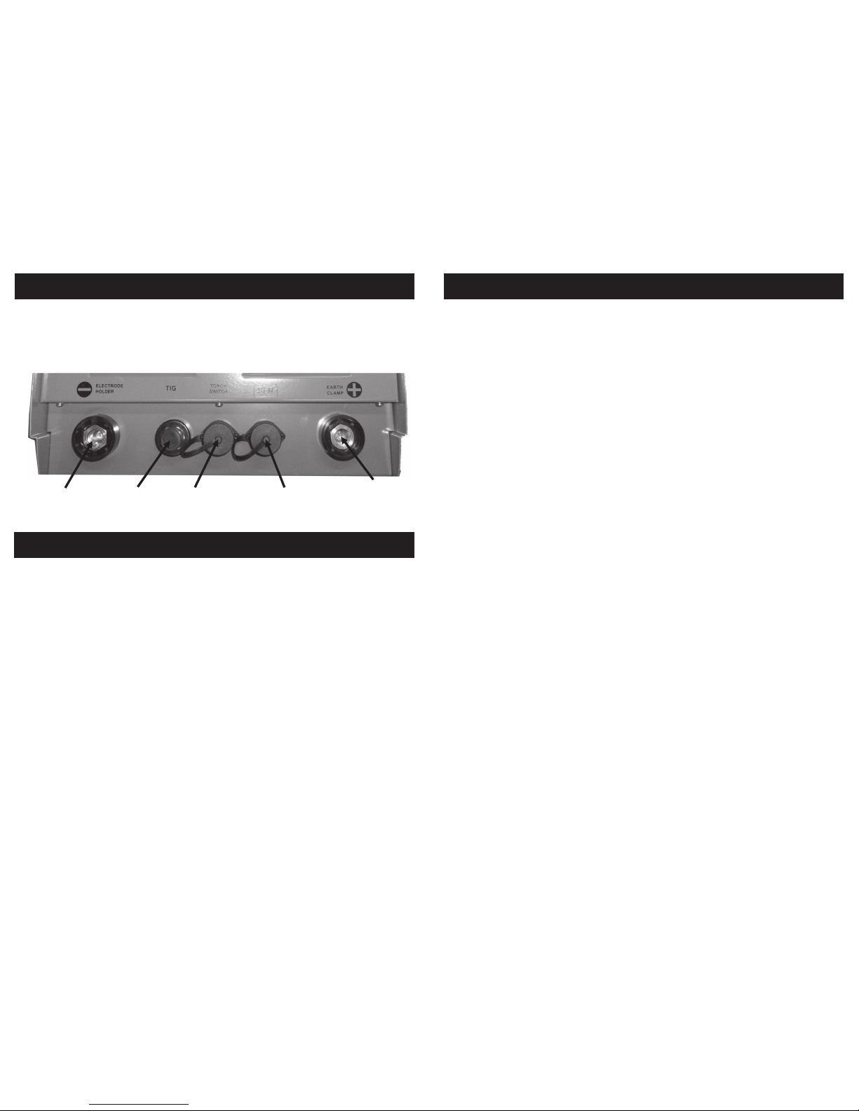
1.Fit electrode holder lead into the power socket specified for the welding electrode
that is to be used, if not specified connect to the positive power socket.
2.Fit earth return lead into the remaining power socket.
3.Connect the welder to the electrical supply using a suitably rated plug.
4.Set the mode switch on front of the P177 to ARC.
5.Set the AC DC switch the match that specified by the rod, if the rod is suitable for
both AC and DC use DC mode.
6.Switch the welder on and adjust the current control until the required current is
shown on the current display, the current value will depend upon the type of metal,
the rod diameter and the thickness of the material to be welded.
7.Perform a short weld test and look at the appearance of the weld bead, adjustment of the current level may be need to get the required weld.
OPERATING INSTRUCTIONS ARC
Remote control
socket
TIG Torch
Fitting
Trigger
socket
Negative power
socket
Positive power
socket
9
SAFETY….cont
wearing an air supplied respirator.
5.Gas leaks in a confined space, should be avoided. Leaking gas in large quantities
can change oxygen concentration dangerously. DO NOT bring gas cylinders into a
confined space.
6.Leaving confined space, shut OFF gas supply at source to prevent possible accumulation of gases in the space if down stream valves are left open, check to be
sure that the space is safe before re entering it.
7.Vapours from chlorinated solvents can be decomposed by the heat of the arc (or
flame) to form PHOSGENE, a highly toxic gas, and other lung and eye-irritating products. The ultra violet (radiant) energy of the arc can also decompose Trichloroethylene and Perchlorethylene. vapours to form phosgene. DO NOT WELD where solvent
vapours can be drawn into the welding atmosphere, or where the radiant energy
can penetrate to atmospheres containing even minute amounts of Trichloroethylene
or perchlorethylene.
Page 10
10
INTRODUCTION
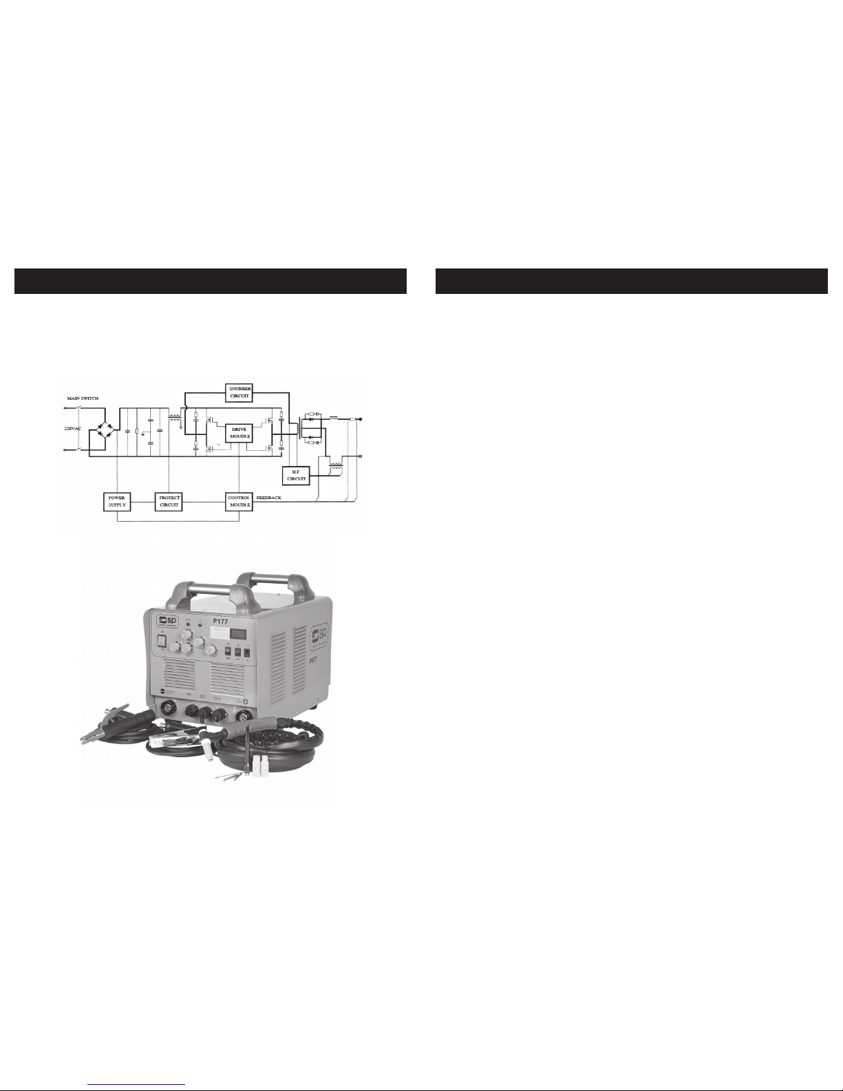
The Weldmate P177 is made with advanced inverter technology.
The inverter works by converting the mains supply at 50Hz to a high frequency voltage at
100KHz, this voltage is then controlled by a PWM system before passing to the transformer and then the rectifier.
15
INSTALLATION….cont
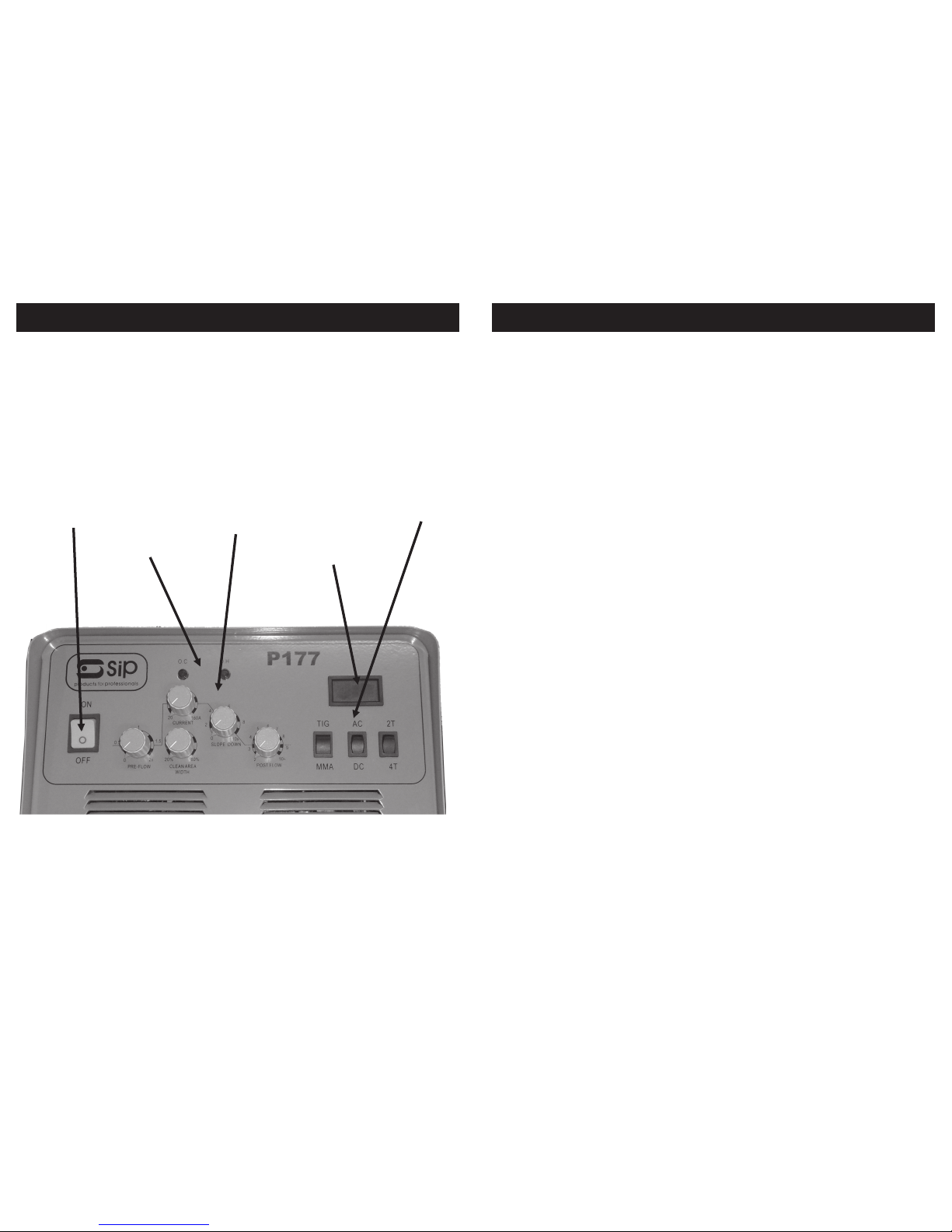
1. Pre flow time, TIG mode Sets a pre-weld gas flow time to purge the weld area.
2. Peak current, Sets the welding current in constant current and the peak current in
3. Clean area width, AC TIG MODE Sets the balance between the cleaning polarity
and the weld polarity in AC mode, 50% = equal time clean and weld.
4. Slope down, TIG MODE Sets the slope down time which starts after the torch trigger
is released, this is the time taken for the current to automatically reduced from the
peak current to zero.
5. Post flow TIG MODE, Sets the post weld gas flow time after the torch trigger is released.
6. TIG - MMA switch, Selects the Welding Process.
7. AC– DC switch , Selects the output current mode.
8. 2T-4T switch, Used in TIG mode, in 2T the welding starts when the torch trigger is
pressed and stops when the trigger released, in 4T welding starts when the trigger is
pressed and is stopped by a second press and release of the torch trigger.
Control Switches
MMA mode - controls 2,6,7 are used
TIG DC mode - controls 1,2,4,5,6,7,and 8 are used
TIG AC mode - controls 1,2,3,4,5,6,7,and 8 are used
Rotary controls
Page 11
14
INSTALLATION
Contents
1 * Inverter based power unit
1 * TIG Torch
1 * Electrode holder lead
1 * Earth return lead
Power switch
Front Panel
Control switches
Rotary controls
Fault lights
Current display
1
2
3
4
5
6
7
8
11
INTRODUCTION….cont
Arc welding more accurately described as Manual Metal Arc welding (MMA) pieces of
metal to be fused together by means of an electric ARC, the arc is generated by
electric current flowing across the gap between the metal being welded and an arc
welding electrode.
The electric arc causes a portion of the metal work piece to melt forming a pool of
molten metal. The arc welding electrode, which is coated with flux to prevent the molten material from reacting with the surrounding atmosphere and to facilitate the stability of the arc. During welding the flux is simultaneously melted/vapourized, this flows to
the molten pool of material shielding it from the air and forms a coating over the cooling weld bead, the coating on the weld bead is called `slag` and is removed after
cooling.
By using inverter technology the weight and volume of product can be reduced, while
the efficiency is raised to 85%, this give a machine that is compact, very portable, controllable and energy efficient.
The P177 is a Dual process machine capable of ARC and TIG welding mild steel, carbon steel, stainless steel, alloy steel, Aluminium and most other nonferrous metals, all
torches and leads are supplied the user only needs to supply a gas regulator, welding
consumables and the item to weld.
Items the user needs to supply.
MMA mode, welding electrodes that match the work being under taken.
TIG mode, argon gas bottle with regulator, welding electrodes that match the work
being under taken.
DC TIG Welding is similar in principle to MMA. An arc is created between the electrode
which is made from a very durable material called Tungsten and the work piece,
causing a portion of the metal work piece to melt forming a molten pool of metal, the
area is shielded by argon gas. A non-fluxed filler rod, compatible with the work material, is added to the molten metal pool to form the weld.
The arc is started by pressing holding the electrode close to the surface and pressing
the torch trigger, a high voltage at high frequency is applied to the electrode, as soon
the air is ionised in the gap between the electrode and work piece the welding power
can flow.
The Tungsten is then drawn away sufficiently to avoid contact whilst still maintaining the
The Processes:
Page 12

12
INTRODUCTION….cont
arc. The distance between the work piece and the Tungsten is governed by the
amount of welding current in use and the Tungsten diameter, as for MMA welding.
Pulse DC TIG this is the same process as DC TIG except the welding current is not at a
constant level. The welding current rises to a peak and falls to the basic level, this enables the welding of thing materials with a reduced risk of melting holes.
AC TIG is used for the welding of aluminium and its alloys, these metals have a hard
heat resistant oxide layer on the surface, the oxide layer needs to be removed in order to produce a strong weld.
During welding the polarity of the torch and work are reversed, when current flows from
the work to the electrode the oxide layer if lifted off, then current flows from the electrode to the work this melts the metal and produce the weld, the repeated polarity
changes clean and melt the area to produce a continues weld.
13
INTRODUCTION….cont
Model 05162
Input Current 11 amps
Input Voltage AC230V 50Hz
No Load Consumption 35 watts
Efficiency 0.85
Power Factor 0.93
Insulation Class F
Protection IP21s
Weight 26 Kg
Unit Dimensions 440x430x600
DC TIG AC TIG ARC
OCV 56V 56V 56V
Operating Voltage 16.4V 16.4V 26.4V
Max Current 160A 160A 160A
Output Current Range 10-600A 10-160A 10-160A
Output at 60% Duty
cycle
160A 160A 160A
Gas Flow 2-5 l/min 2-5 l/min
Arc starting HF HF Manual
TECHNICAL SPECIFICATIONS
 Loading...