

Page 1
20
FOR HELP OR ADVICE ON THIS PRODUCT PLEASE CONTACT YOUR DISTRIBUTOR,
OR SIP DIRECTLY ON:
TEL: 01509500400
EMAIL: [email protected] or [email protected]
www.sip-group.com
Ref: 220116
Please dispose of packaging for the product in a responsible
manner. It is suitable for recycling. Help to protect the
environment, take the packaging to the local amenity tip and
place into the appropriate recycling bin.
Please read and fully understand the instructions in this manual
before operation. Keep this manual safe for future reference.
03695
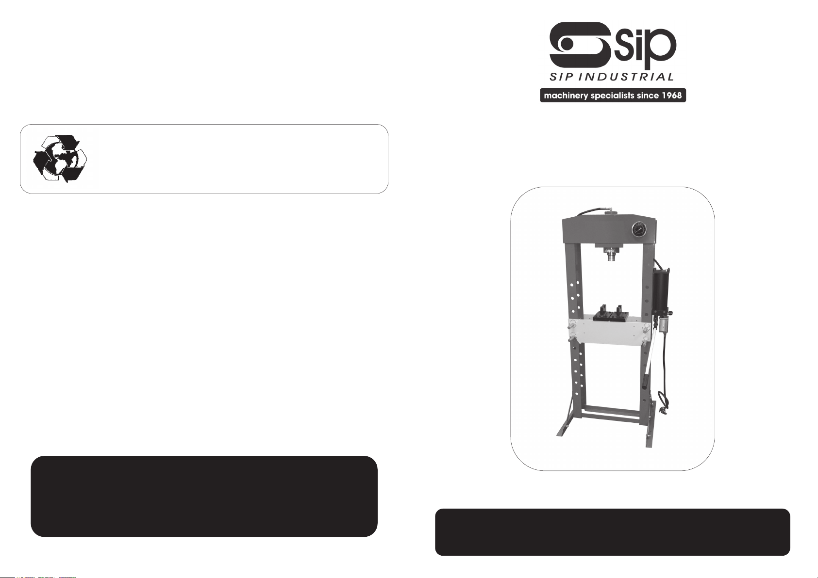
30 Ton Shop Press
(Pneumatic/Hydraulic)
Page 2
2
19
DECLARATION OF CONFORMITY
Declaration of Conformity
We
SIP (Industrial Products) Ltd
Gelders Hall Road
Shepshed
Loughborough
Leicestershire
LE12 9NH
England
As the manufacturer's authorised representative within the EC
declare that the
30 Ton Shop Press (Pneumatic/Hydraulic) - SIP Part. No. 03695
Conforms to the requirements of the following directive(s), as indicated.
2006/42/EC Machinery Directive
Signed: …………………………………...
Mr P. Ippaso - Managing Director - SIP (Industrial Products) Ltd
Date: 20/01/2015.
And the relevant standard(s), including:
EN ISO 12100:2010
EN 1494:2000+A1:2008
Page 3
18
NOTES
3
CONTENTS
Page No. Description
4. Safety Symbols Used Throughout This Manual
4. Safety Instructions
6. Guarantee
7. Contents and Accessories
8. Technical Specifications
9. Getting to Know Your Shop Press
10. Assembly Instructions
12. Operating Instructions
13. Maintenance
14. Troubleshooting
15. Exploded Diagram
16. Parts List
19. Declaration of Conformity
Page 4
4
SAFETY SYMBOLS USED THROUGHOUT THIS MANUAL
When using your Shop Press, basic safety precautions should always be followed to
reduce the risk of personal injury and / or damage to the Shop Press or load.
Read all of these instructions before operating the Shop Press and save this user manual for future reference.
The Shop Press should not be modified or used for any application other than that for
which it was designed.
It was designed for the removal or installation of bearings, universal joints, pulleys, etc.
If you are unsure of its relative applications do not hesitate to contact us and we will
be more than happy to advise you.
Before operating the Shop Press always check no parts are broken, that no oil is leaking and that no parts are missing.
Always operate the Shop Press safely and correctly.
KNOW YOUR SHOP PRESS: Read and understand the owner's manual and labels affixed to the Shop Press. Learn its applications and limitations, as well as the potential
hazards specific to it.
KEEP CHILDREN AND UNTRAINED PERSONNEL AWAY FROM THE WORK AREA: All visitors
should be kept at a safe distance from the work area; never allow untrained persons
to operate the Shop Press. .
STAY ALERT: Always watch what you are doing and use common sense.
NEVER LEAVE THE SHOP PRESS UNATTENDED: When in use / under load.
HAVE YOUR SHOP PRESS REPAIRED BY A QUALIFIED PERSON: The Shop Press is in ac-
cordance with the relevant safety requirements. Repairs should only be carried out by
qualified persons using original spare parts, otherwise this may result in considerable
danger to the user and void the warranty.
DANGER! Check that the shop press is in sound condition and good working order;
SAFETY INSTRUCTIONS
Danger / Caution: Indicates risk of personal injury and/or the possibility of
damage.
IMPORTANT: Please read the following instructions carefully, failure to do
so could lead to serious personal injury and / or damage to the Shop
Press.
Note: Supplementary information.
17
NOTES
Page 5
16
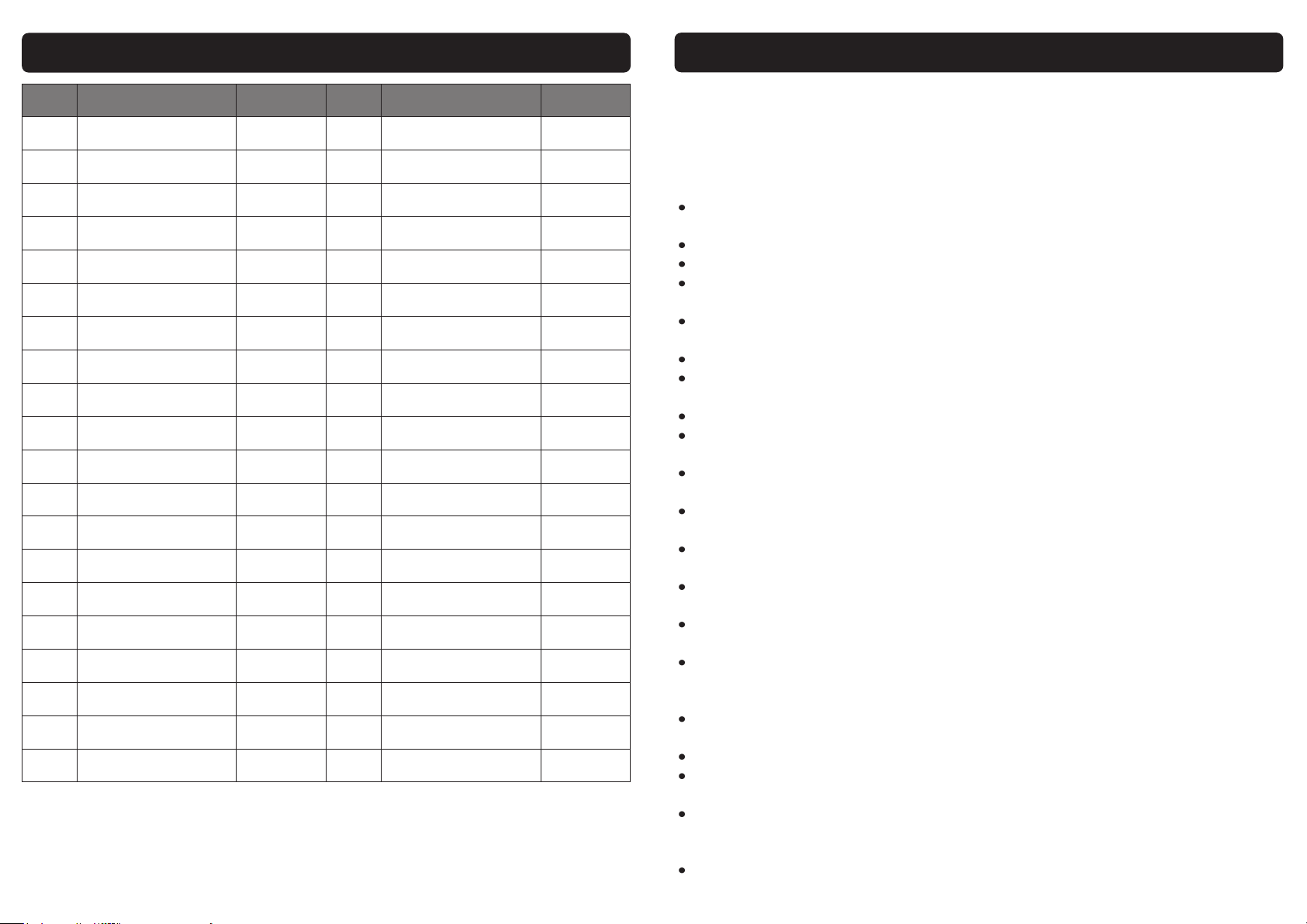
PARTS LIST
Ref. No. Description SIP Part No. Ref. No. Description SIP Part No.
1.
Frame
HY02-00170 21.
Hydraulic hose
HY02-00190
2.
Leg
HY02-00171 22.
O-ring
HY02-00191
3.
Support Bar
HY02-00172 23.
Connector
HY02-00192
4.
Bed
HY02-00173 24.
Bolt
HY02-00193
5.
Bed support pin clip
HY02-00174 25.
Lock Washer
HY02-00194
6.
Bed support pin
HY02-00175 26.
Washer
HY02-00195
7.
Bolt
HY02-00176 27.
Connector
HY02-00196
8.
Washer
HY02-00177 28.
Nut
HY02-00197
9.
Lock Washer
HY02-00178 29.
Screw
HY02-00198
10.
Nut
HY02-00179 30.
Manometer fitting
HY02-00199
11.
Bolt
HY02-00180 31.
Nylon washer
HY02-00200
12.
Spring
HY02-00181 32.
Manometer
HY02-00201
13.
Connector
HY02-00182 33.
Hydraulic hose
HY02-00202
14.
R-Pin
HY02-00183 34.
Pump assembly
HY02-00203
15.
Adjuster
HY02-00184 35.
Pump handle
HY02-00204
16.
Ram assembly
HY02-00185 36.
Pump handle cover
HY02-00205
17.
Screw
HY02-00186 41.
Arbor plate
HY02-00206
18.
Ram support plate
HY02-00187 N/A.
Air motor
HY02-00150
19.
Bolt
HY02-00188 N/A.
Air valve HY02-00148
20.
Screw
HY02-00189 N/A.
Air hose HY02-00149
5
SAFETY INSTRUCTIONS….cont
Take immediate action to repair or replace damaged parts.
WARNING! Only operate on a level and stable surface and never use on soft ground
where the Shop Press is likely to “sink” whilst in operation.
NEVER STAND ON THE SHOP PRESS: The Shop Press is not designed for this purpose.
DO NOT dismantle or tamper with the Shop Press, as this may be dangerous and will
invalidate the warranty.
If a problem with the Shop Press is experienced or suspected stop using the Shop
Press immediately and contact your distributor for repair.
Do not attempt to press a load that exceeds the rated capacity of the Shop Press.
Never work under the Shop Press whilst in operation.
Regularly inspect, clean and lubricate the Shop Press, ensuring that it is in good
working order and condition.
Always ensure that the work area is clean and tidy, free from unrelated materials and
has adequate lighting.
Keep hands, limbs etc. clear of moving parts during operation of the ram.
DO NOT top-up the Shop Press with brake fluid, or other oil types; use hydraulic oil
only.
DO NOT adjust the safety overload valves.
Ensure that there are no persons or obstructions beneath the Shop Press whilst its in
operation.
Clean the Shop Press correctly, with the ram in the down position, but DO NOT leave
it extended.
Failure to follow the warnings in this manual, may result in personal injury and/or
property damage.
Prior to applying the load, be sure that the hydraulic ram collar threads are fully engaged to the head assembly.
Components of this Shop Press are specially designed to withstand the rated capacity. Do not substitute bolts, pins, or any other components.
Always press the load on the centre of the ram. Offset loads can damage the ram,
and may cause a workpiece to eject.
Before operating, check for signs of cracked welds, bent bed support pins, loose or
missing bolts, or any other structural damage. Do not operate if any of these conditions exist. Have repairs made only by authorised service centre.
Remove all loads and arbor plates from the bed before attempting to adjust the
bed height.
Press only on the workpiece supported by the bed and arbor plates.
When using accessories, such as arbor plates, be sure that they are centered on
the bed, and are in full contact with the bed.
Parts being pressed may splinter, shatter or eject from the press. Due to various applications, it is your responsibility to always use adequate guards, such as eye protection and heavy protective clothing, when operating this Shop Press.
Do not stand in front of work area where the load is applied.
Page 6
6
SAFETY INSTRUCTIONS….cont
If the Shop Press appears to be damaged in any way, is found to be badly worn, or
operates abnormally IT SHOULD BE REMOVED FROM SERVICE until necessary repairs
are made by an authorised service centre.
DO NOT use the Shop Press to compress springs or any other item that could disengage and cause a potential hazard.
Understand the operating environment; Before each use the operator should assess,
understand and where possible reduce the specific risks and dangers associated
with the operating environment. Bystanders should also be made aware of any risks
associated with the operating environment.
CAUTION: The warnings and cautions mentioned in this user manual can not cover all
possible conditions and situations that may occur. It must be understood by the operator that common sense and caution are factors which cannot be built into this product, but must be applied.
Danger / Caution: Never exceed the maximum capacity of 30 ton, overloading can lead to personal injury or damage to the Shop Press.
This SIP Shop Press is covered by a 12 month parts and labour warranty covering failure
due to manufacturers defects. This does not cover failure due to misuse or operating
the Shop Press outside the scope of this manual - any claims deemed to be outside
the scope of the warranty may be subject to charges Including, but not limited to
parts, labour and carriage costs.
This guarantee does not cover consumables such as oil, arbor plates etc.
In the unlikely event of warranty claims, contact your distributor as soon as possible.
GUARANTEE
Note: Proof of purchase will be required before any warranty can be hon-
oured.
15
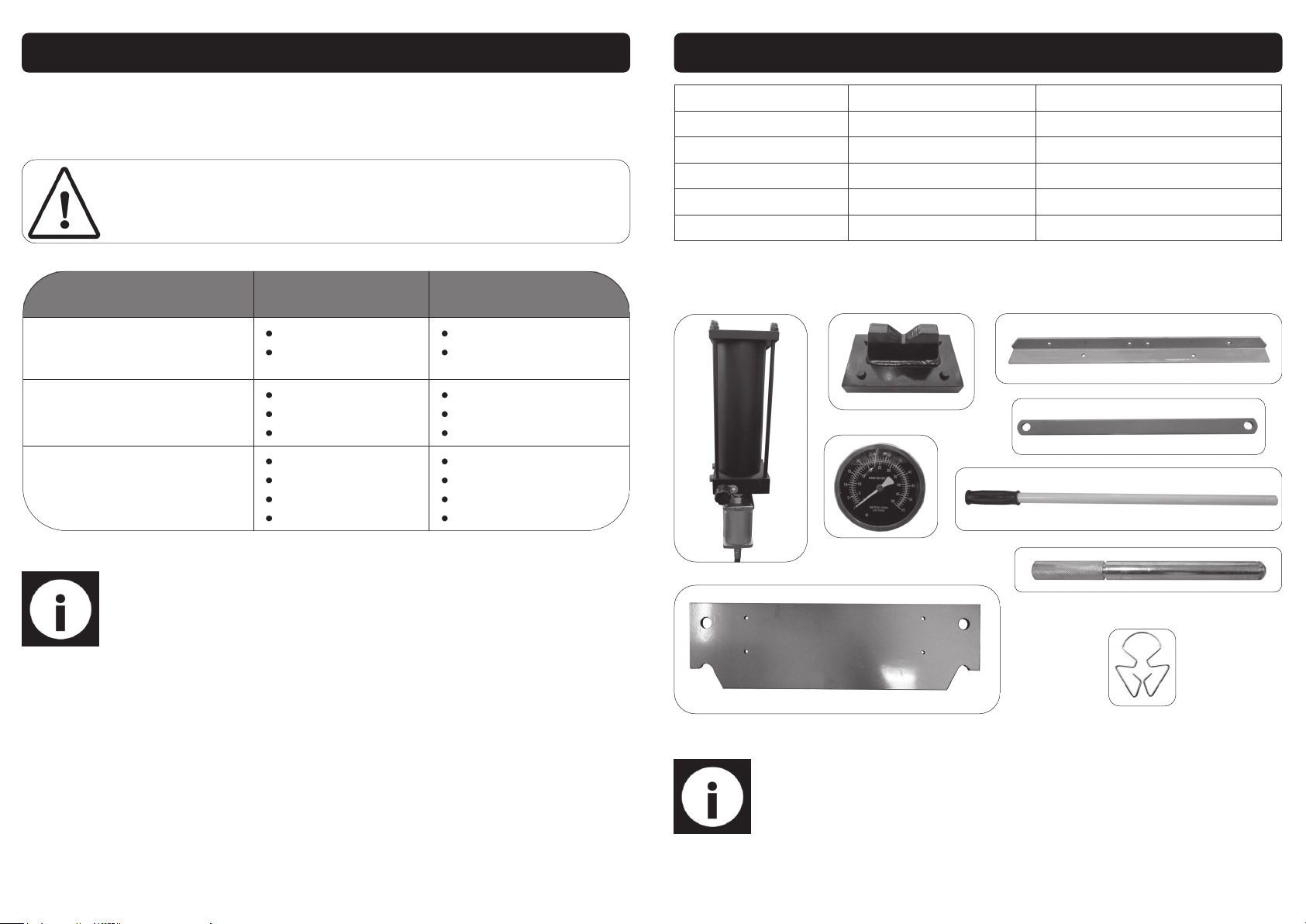
EXPLODED DIAGRAM
Page 7
14
TROUBLESHOOTING
The following form lists the common operating issues with problems and solutions.
Please read the form carefully and follow it.
If any of the following symptoms occurs during your operation, stop using the Shop Press immediately, or
serious personal injury could result. Only a qualified person or an authorised service centre should perform
repairs on the Shop Press. Disconnect from the air supply before attempting repairs or adjustments. When
replacing parts etc.
Note: Repairs should be carried out by a qualified person.
FAULT POSSIBLE CAUSES POSSIBLE REMEDIES
Loses pressure under load.
Release valve is open.
Pump or piston fault.
Close release valve.
Replace pump.
Pump feels spongy during pumping, or
lever has lost stroke.
Pump low on oil.
Air trapped in pump.
Pump or ram fault.
Top up with oil.
Bleed air out of system.
Replace pump/ram.
Ram is weak or does not reach rated
pressing capacity.
Pump low on oil.
Air trapped in pump.
Release valve is open.
Pump or piston fault.
Top up with oil.
Bleed air out of system.
Close release valve.
Replace pump.
7
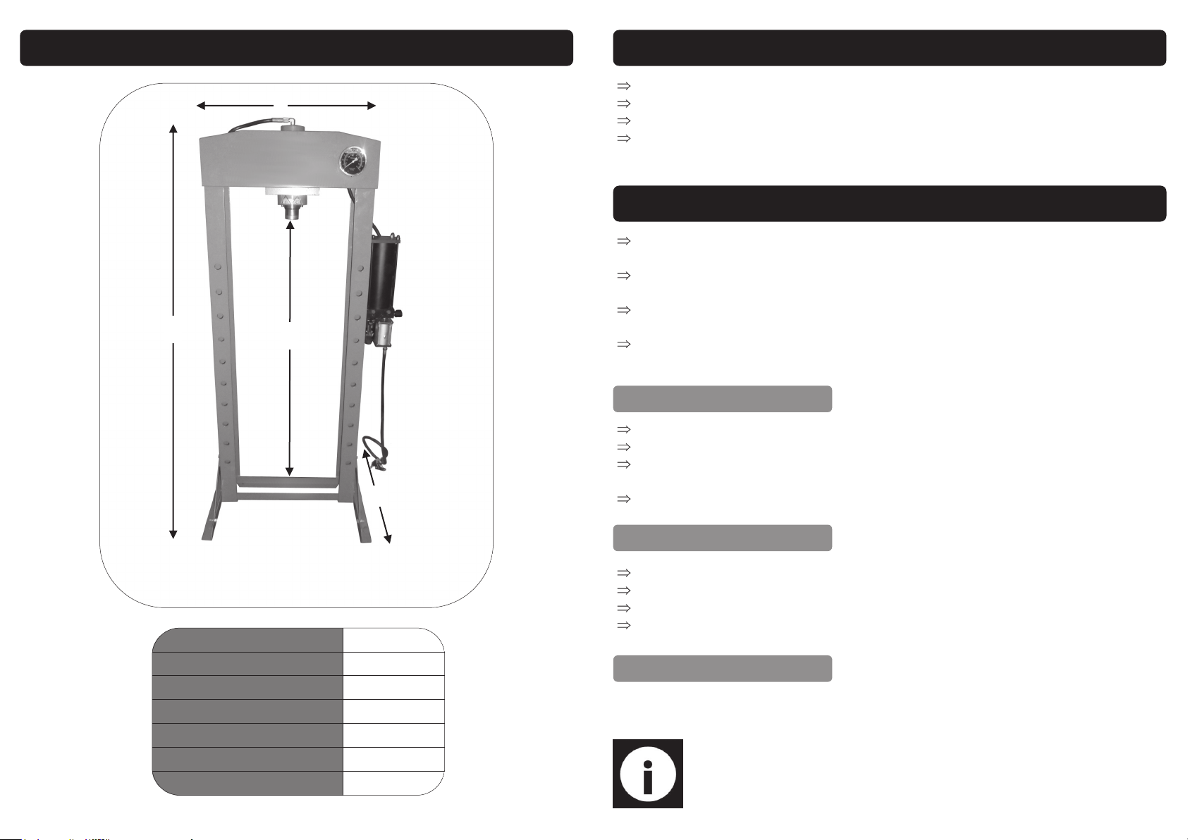
CONTENTS & ACCESSORIES
Note: If any of the above are missing or damaged, contact your distributor
immediately.
1
2
3
4
5
6
7
8
9
1. Hydraulic Pump 7. Bed N/A. M10 x 20 Bolt (x4)
2. Arbor plate (x2) 8. Bed Pin (x4) N/A. 10mm Washer (x16)
3. Manometer 9. Bed Pin Clip (x8) N/A. 10mm Spring Washer (x12)
4. Leg (x2) N/A. Frame (c/w ram) N/A. Nut M10 (x12)
5. Leg Support (x4) N/A. Instruction Manual
6. Pump Handle N/A. M10 x 35 Bolt (x12)
Page 8
8
TECHNICAL SPECIFICATIONS
A
B
C
D
Height (A) 1830mm
Width (B) 915mm
Depth (C) 700mm
Working range (D) 151 - 1031mm
Ram Stroke 150mm
Bed Width 535mm
Operating Air Pressure 7 - 8 Bar
13
MAINTENANCE
Periodically check the press frame to make sure all bolts are tight and inspect
for cracked welds, bent, loose, or missing parts.
Periodically check hydraulic connections for possible leaks, replace or properly
repair damaged or leaking hydraulic components before use.
Change hydraulic oil in the hydraulic system every 100 working hours, or more
frequently in unusual dirty or dusty areas.
If the paint becomes badly chipped, it is suggested to repaint the press. This will
prevent rusting.
Make sure the ram is fully retracted.
Remove the air vent / oil fill screw.
Fill with hydraulic oil (#22 ISO6743) through the oil fill hole, until the oil reaches the
top of the oil chamber.
Refit the air vent / oil fill screw.
ADDING OIL
BLEEDING
Loosen the air vent / oil fill screw.
Insert the handle into the handle base.
Pump the handle about 10 times, this will purge the air out of the system.
retighten the air screw.
Once the work is done release the air valve lever (or stop pumping the handle).
Turn the release valve anti-clockwise to retract the ram.
When the ram has fully retracted, remove the workpiece.
If no more work is to be done, then disconnect from the air supply and retighten
the release valve and air vent / oil fill screw.
OPERATING INSTRUCTIONS….cont
CLEANING
Periodically check the ram and ram piston for signs of rust or corrosion. Clean as
needed and wipe with an oily cloth.
Note: Never use sandpaper or abrasive material on these surfaces.
Page 9
12
OPERATING INSTRUCTIONS
Place the bed to your desired height, use the bed support pin (x4) and bed
support pin clips (x8) to secure in place.
Place the arbor plate on the bed, then place the workpiece onto the arbor
plate.
Danger / Caution: At all times use all 8 bed support pin clips to secure the bed support
pins, using without the bed support pin clips is dangerous, this could cause injury to you
or any one in the vicinity, this will also damage the Shop Press and void your warranty.
Turn the release valve clockwise to close it
(007).
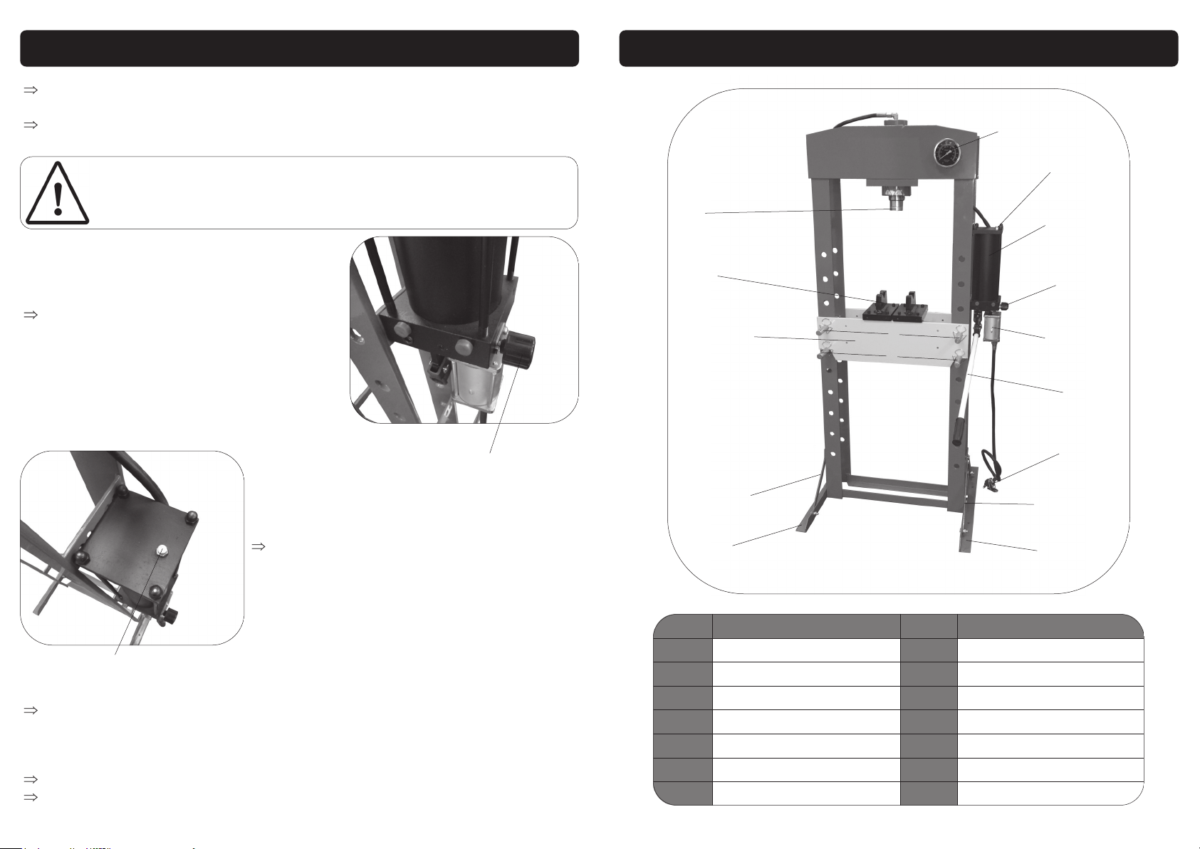
Air vent / oil fill screw
008
Open the air vent / oil fill screw on the hydraulic pump (008).
Connect the air supply to the air valve inlet connection, press the air valve lever
down and the ram will start too move (use the pump handle if no air supply is
available), once the serrated saddle is near the workpiece take your hand off
the air valve lever (or stop pumping the handle).
Align the workpiece and ram to ensure centre loading.
Press the air valve lever down again (or pump the handle) to start the pressing.
007
Release valve
9
GETTING TO KNOW YOUR SHOP PRESS
Ref. No Description Ref. No Description
1. Leg 8. Air Vent / Oil Filler Screw
2. Leg Supports 9. Hydraulic Pump
3. Bed Pin 10. Release Valve
4. Bed 11. Air Motor
5. Arbor Plate 12. Pump Handle
6. Hydraulic Ram 13. Air Valve
7. Manometer
4
5
6
1
2
7
9
10
12
1
2
3
3
8
11
13
Page 10
10
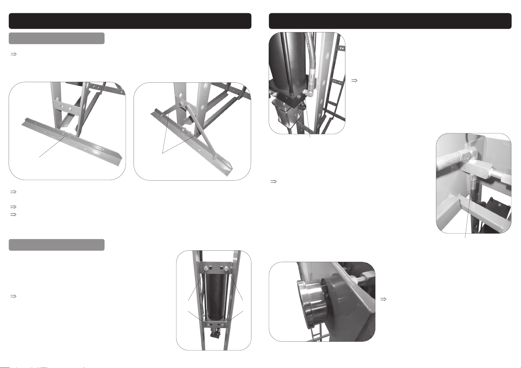
ASSEMBLY INSTRUCTIONS
Connect the leg to either the left or right post by using the M10x35 bolt (x2), 10mm
washer (x2), 10mm spring washer (x2) and M10 nuts (x2), do not tighten fully just yet
(001).
Connect both leg supports to the post and leg, by using M10x35 bolt (x4), 10mm
washer (x4), 10mm spring washer (x4) and M10 nuts (x4) (002).
Repeat the process for the other post.
Make sure everything is level, then proceed to tighten all the bolts.
Leg support
002
Leg
001
FITTING THE LEGS
FITTING THE HYDRAULIC PUMP
Bolt the hydraulic pump to the side of the frame, by
using M10x20 bolt (x4) & 10mm washer (x4) (003).
Bolt
Bolt
003
11
ASSEMBLY INSTRUCTIONS….cont
004
Lower fitting
005
Upper fitting
006
Connect the hydraulic hose onto the lower fitting on
the ram (004).
Connect the other side of the hydraulic hose to the
manometer fitting, located inside the frame at the top
(005).
Lastly screw the manometer in to the manometer fitting (006).
 Loading...