

Page 1
16
FOR HELP OR ADVISE ON THIS PRODUCT PLEASE CONTACT YOUR DISTRIBUTOR,
OR SIP DIRECTLY ON:
TEL: 01509500400
EMAIL: [email protected] or [email protected]
www.sip-group.com
Please dispose of packaging for the product in a responsible
manner. It is suitable for recycling. Help to protect the
environment, take the packaging to the local amenity tip and
place into the appropriate recycling bin.
Ref: 030413
1
Chainsaw
Log Horse
Please read and fully understand the instructions in
this manual before operation. Keep this manual
01979
Page 2

2
15
PARTS LIST
Ref. No. Description Sip Part No.
1. Bolt M8x30
WD03-00170
2. Bolt M8x35
3. Bolt M8x45
4. Bolt M8x70
5. Bolt M10x20
6. Cap head bolt M8x12
7. Nut M8
8. Eye bolt M12x30
9. Eye bolt M10x20
12. R Clip
14. Pin
16. Measuring rod knob
10. Guard WD03-00171
11. Pivot clamp WD03-00172
13. Pivot clamp support WD03-00173
15. Measuring rod WD03-00174
17. Measuring rod support WD03-00175
18. Left support leg WD03-00176
19. Foot WD03-00177
20. Leg support WD03-00178
21. Front table WD03-00179
22. Rear table WD03-00180
23. Right support leg WD03-00181
24. Main leg WD03-00182
Page 3

14
EXPLODED DIAGRAM
3
CONTENTS
Page No. Description
4 Safety Symbols Used Throughout This Manual
4 Safety Instructions
6 Guarantee
6 Contents & Accessories
7 Technical Specifications
8 Assembly Instructions
14 Exploded Diagram
15 Parts List
Page 4
4
SAFETY INSTRUCTIONS
Danger / Caution: Indicates risk of personal injury and/or the possibility of
damage.
SAFETY SYMBOLS USED THROUGHOUT THIS MANUAL
Note: Supplementary information.
IMPORTANT: Please read the following instructions carefully, failure to do so could
lead to serious personal injury and / or damage to the saw horse.
When using your saw horse, basic safety precautions should always be followed to
reduce the risk of personal injury and / or damage to the saw horse.
Read all of these instructions before operating the saw horse and save this user manual for future reference.
The saw horse should not be modified or used for any application other than that for
which it was designed; It was designed to support logs prior to and during cutting operations.
If you are unsure of its relative applications do not hesitate to contact us and we will
be more than happy to advise you.
Before using the saw horse always check no parts are broken, that all screws are completely tight and that no parts are missing.
Always use the saw horse safely and correctly.
KNOW YOUR SAW HORSE: Read and understand the owner's manual and labels affixed to the saw horse. Learn its applications and limitations, as well as the potential
hazards specific to it.
DO NOT USE THE SAW HORSE IN DANGEROUS ENVIRONMENTS: Do not use your saw
horse on uneven or unstable ground.
KEEP CHILDREN AND UNTRAINED PERSONNEL AWAY FROM THE WORK AREA: All visitors
should be kept at a safe distance from the work area.
STAY ALERT: Always watch what you are doing and use common sense.
HAVE YOUR SAW HORSE REPAIRED BY A QUALIFIED PERSON: The saw horse is in ac-
cordance with the relevant safety requirements. Repairs should only be carried out
by qualified persons using original spare parts, otherwise this may result in considera-
13
Fig. 7
ASSEMBLY INSTRUCTIONS….cont
Fig. 6
Eye Bolt
Page 5
12
ASSEMBLY INSTRUCTIONS….cont
Note: Ensure that the bar is approximately 90° to the clamp and the
chain is well clear of the stand before tightening the eye-bolt. Once tightened, test the arc of travel by hand to make sure that the moving parts of
the chainsaw does not touch any part of the saw bench.
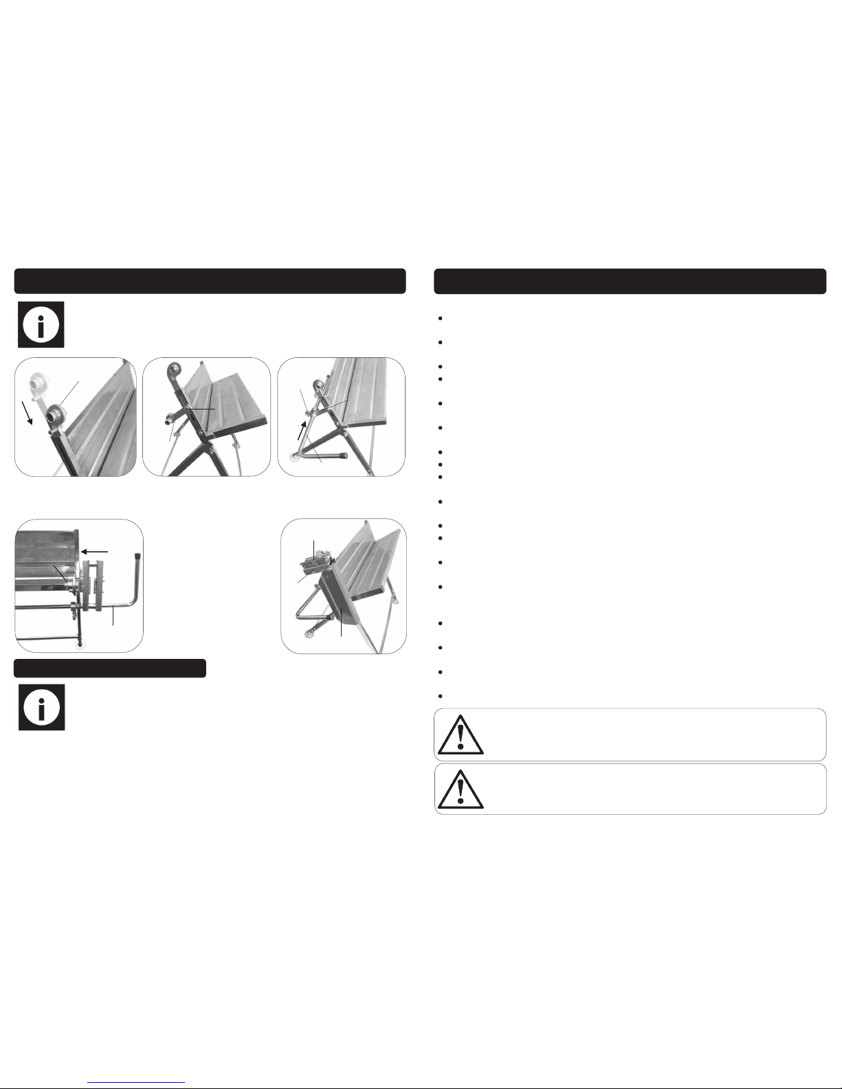
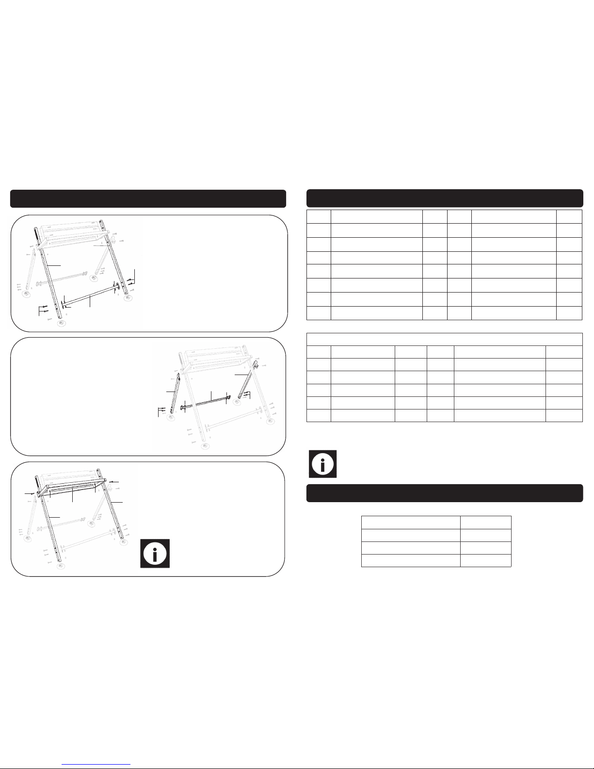
5. Fit the guard (M) onto the pivot clamp (N), use the bolt (M8x70) and nut (M8) to
secure (Fig. 5).
Note: The pivot clamp support can be adjusted vertically, to match the
dimensions of different saws and logs.
Fig. 1
Pivot Support
Clamp
Fig. 3
Measuring Rod
Support
Fig. 2
Bolt
Eye Bolt
Measuring Rod
Support
Measuring Rod
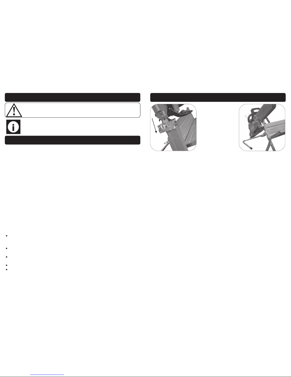
1. Carefully lower the chainsaw bar into position between the two solid blocks in the
pivot clamp. Ensure that the brake on the saw still operates when the saw is fully
seated; slide the saw in / out until this is achieved. (Fig. 6).
2. Once the saw is in the desired position secure in place with the eye-bolt (M12x30).
(Fig. 7).
Fig. 4
Measuring Rod
R-Clip
Fig. 5
Guard
Pivot Clamp
Bolt
ATTACHING THE CHAINSAW
5
SAFETY INSTRUCTIONS….cont
ble danger to the user and void the warranty.
DANGER! Check that the saw horse is in sound condition and good working order
before each use. Take immediate action to repair or replace damaged parts.
Use recommended parts only - Unapproved parts may be dangerous and will invalidate the warranty.
WARNING! Never stand on the saw horse or use it as an improvised ladder.
WARNING! Do not allow untrained persons to use the saw horse and do not operate
when under the influence of drugs or alcohol.
DO NOT dismantle or tamper with the saw horse, as this may be dangerous and will
invalidate the warranty.
ALWAYS make sure the load weight is not exceeded, this will cause damage to the
saw horse and cause personal injury.
If a problem with the saw horse is experienced contact your distributor for repair.
Never exceed the rated capacity of 120kg.
Never use a chainsaw guide bar longer than 450mm, this is dangerous and could
lead to personal injury, or injury to others.
Never use wood that is longer than 1800mm and 200mm in diameter, this will
cause the saw horse to be unstable and unsafe to the operator and bystanders.
Never make any alterations to this product.
Failure to follow the warnings in this manual, may result in personal injury and/or
property damage.
Before using the saw horse, ensure all nuts and bolts are tight on the stand and
guard.
When using a chainsaw (not supplied) with this saw horse, it is vital that all safety precautions are followed by the chainsaw manufacturer, if in any doubt contact the
chainsaw manufacturer for more information on safety precautions.
Always use safety goggles or safety glasses & dust mask, when using this saw horse
with a chain saw.
The saw horse is not a substitute to the normal safety gear used during chain sawing
operations.
Never wear loose fitting clothes and tie long hair etc. to ensure that they cannot get
dragged into moving parts on the chainsaw.
Ensure the nuts and bolts on the pivot clamp and guard are kept tight at all times.
Caution: The warnings and cautions mentio ned in this user manual can not cover al l possible conditions and situations that may occur. It must be understood by the op erator that commo n sense
and caution are factors which cannot be b uilt into this product, but must be applied.
Danger: Never overload the saw horse during operation, overloading can lead to
personal injury or damage to the saw horse.
Page 6
6
GUARANTEE
This SIP Saw Horse is covered by a 12 month parts and labour warranty covering failure
due to manufacturers defects. This does not cover failure due to misuse or operating
the fan outside the scope of this manual - any claims deemed to be outside the
scope of the warranty may be subject to charges Including, but not limited to parts,
labour and carriage costs.
In the unlikely event of warranty claims, contact your distributor as soon as possible.
Proof of purchase will be required before any warranty can be honoured.
Note: Proof of purchase will be required before any warranty can be honoured.
CONTENTS & ACCESSORIES
O
L
M
N
R
Q
P
11
1. Slide the pivot clamp support (P) into the main leg (F), either to the left or right hand
side of the stand depending upon the operators preferred choice (Fig 1).
2. Bolt the measuring rod support (O) onto the pivot clamp support using the supplied
bolt (M8x20) (Fig 2).
3. Remove the cap from the long end of the measuring rod (R) and slide it through
the measuring rod support (O); use the eye bolt (M10x20) to secure (Fig. 3).
4. Slide the pivot clamp onto the pivot clamp support, and use the R-Clip to secure it
Note: Take care not to over-tighten the nuts/bolts to reduce the risk of
damaging the tubing. The nuts / bolts need to be just tight enough to ensure that the stand is sturdy and secure.
FITTING THE CHAINSAW HOLDER
Note: When using a chainsaw (not supplied) with this saw horse, it is vital
that all safety precautions are followed by the chainsaw manufacturer, if
in any doubts contact the chainsaw manufacturer for more information.
ASSEMBLY INSTRUCTIONS….cont
B
L
L
B
B
L
B
L
E
E
E
E
9. Lastly fit the feet (L) to the bottom of the stand, using bolts
(B) and nuts (E).
Note: Do not over-tighten the nut/
bolt as t here s hould be some
movement to allow the feet to pivot.
Page 7
10
ASSEMBLY INSTRUCTIONS….cont
F
A
G
A
F
E
E
E
E
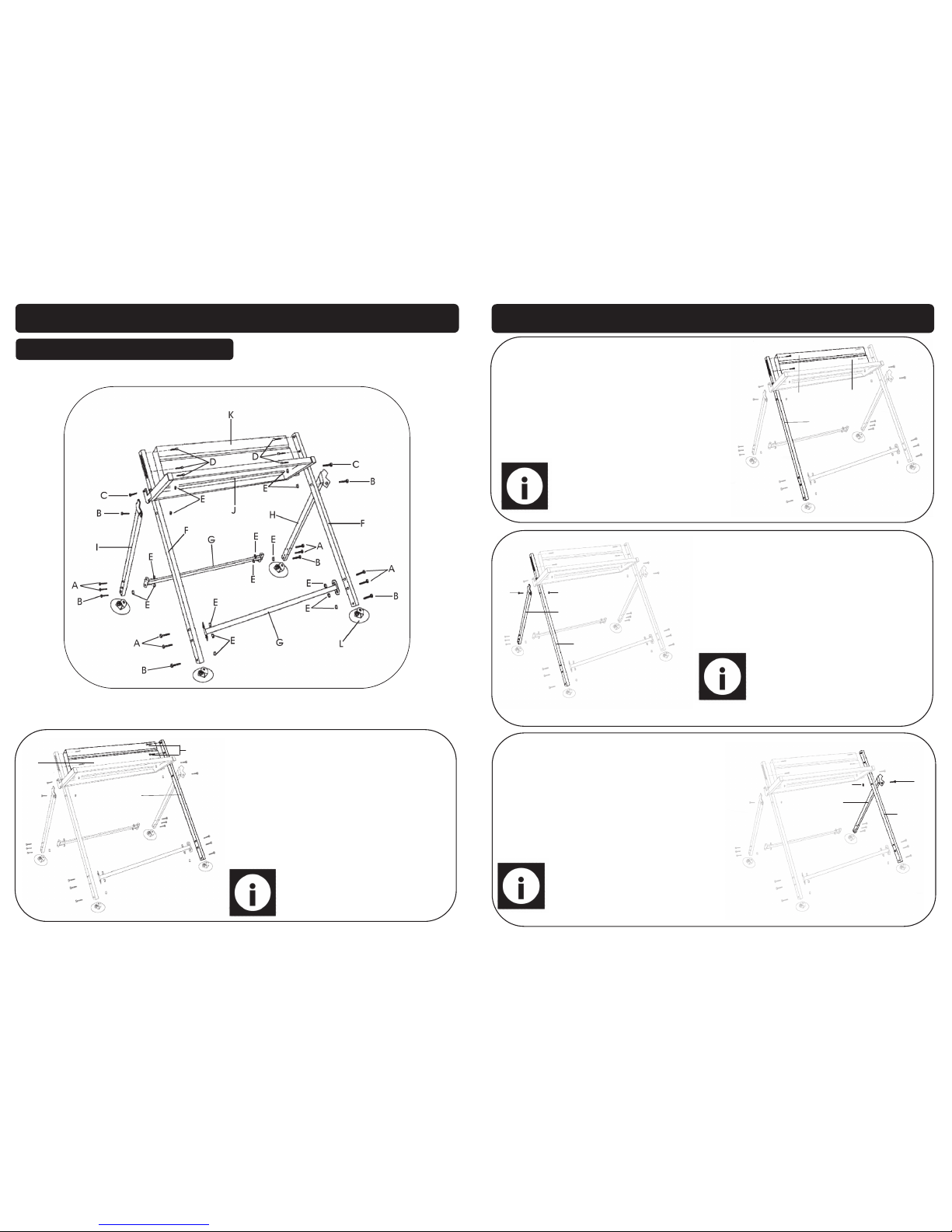
6. Now fit the leg support (G) to both
sides of the main leg (F), use bolts (A)
and nuts (E) to secure.
A
A
I
H
E
E
E
E
G
7. Fit the other leg support (G) to the
left and right support legs (I & H), use
bolts (A) and nuts (E).
C
F
F
E
J
E
C
8. Now fit the front table (J) to both sides
of the main leg (F), use bolts (C) and
nuts (E) to secure.
Note: Do not over-tighten the nut/
bolt as there should be some movement to allow the table to pivot.
7
TECHNICAL SPECIFICATIONS
Maximum wood length 1800mm
Maximum wood diameter 200mm
Maximum load 120kg
Maximum guide bar 450mm
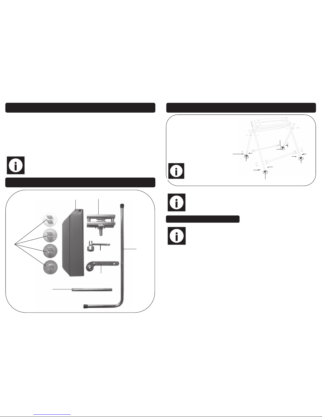
Ref. Description Qty. Ref. Description Qty.
L Foot 4 N/A Front Table 1
M Guard 1 N/A Rear Table 1
N Pivot Clamp 1 N/A Right Support Leg 1
O Measuring Rod Support 1 N/A Left Support Leg 1
P Pivot Clamp Support 1 N/A Leg Support 2
Q Eye Bolt Bar 1 N/A Main Leg 2
R Measuring Rod 1 N/A = Not Pictured N/A
Note: If any of the above are missing or damaged, contact your distributor
immediately.
*Chainsaw is not supplied.
Fixing Kit
Ref. Description Qty. Ref. Description Qty.
Bolt (M8x30) 8 Eye Bolt (M10x20) 1 A N/A
Bolt (M8x35) 6 R-Clip 1 B N/A
Bolt (M8x45) 2 Bolt (M10x20) 1 C N/A
Bolt (M8x70) 1 Cap Head Bolt (M8x12) 6 N/A D
Eye Bolt (M12x30) 1 Nut (M8) 17 N/A E
CONTENTS & ACCESSORIES….cont
Page 8
8
ASSEMBLY INSTRUCTIONS
F
K
D
Note: There are only 2 bolts shown
on the picture, but there are 3 bolts
used to secure.
1. Locate the main leg (F) and rear
table (k).
2. Bolt the rear table (k) to the main
leg (F) using the cap head bolts
supplied (D).
BUILDING THE MAIN STAND
9
ASSEMBLY INSTRUCTIONS….cont
F
D K
Note: There are only 2 bolts shown
on the picture, but there are 3 bolts
used to secure.
3. Fit the 2nd main leg (F) to the opposite
side, using the same cap head bolts
(D).
I
E
B
F
4. Now fasten the left support leg (I) to the
main leg (F) using bolt (B) and nut (E).
H
E
B
F
5. Repeat step 4 but use the right leg support (H).
Note: Do not over-tighten the nut/bolt
as there should be some movement
to allow the support to pivot.
Note: Do not over-tighten the nut/
bolt as there should be some movement to allow the support to pivot.
 Loading...