

Page 1
24
FOR HELP OR ADVISE ON THIS PRODUCT PLEASE CONTACT YOUR DISTRIBUTOR,
OR SIP DIRECTLY ON:
TEL: 01509500400
EMAIL: [email protected] or [email protected]
www.sip-group.com
Please dispose of packaging for the product in a responsible
manner. It is suitable for recycling. Help to protect the
environment, take the packaging to the local amenity tip
and place into the appropriate recycling bin.
Never dispose of electrical equipment or batteries in with
your domestic waste. If your supplier offers a disposal facility please use it or alternatively use a recognised re-cycling
agent. This will allow the recycling of raw materials and help
protect the environment.
Ref: 031212
1
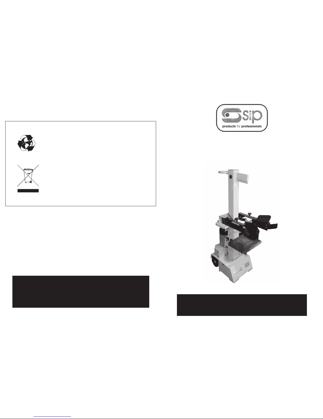
7 Ton Log Splitter
Please read and fully understand the instructions in
this manual before operation. Keep this manual
safe for future reference
01977
Page 2

2
23
Declaration of Conformity
We
SIP (Industrial Products) Ltd
Gelders Hall Road
Shepshed
Loughborough
Leicestershire
LE12 9NH
England
As the manufacturer's authorised representative within the EC
declare that the
7 Ton log splitter - SIP Pt. No. 01977
Suppliers Part No. LS7S
Conforms to the requirements of the following directive(s), as indicated.
2006/95/EC Low Voltage Directive
2006/42/EC Machinery Directive
2004/108/EC EMC Directive
2002/95/EC ROHS Directive
As Amended By
2008/35/EC
And the following harmonised standard(s)
EN 55014-1:2006+A1
EN 55014-2:1997+A1+A2
EN 61000-3-2:2006+A1+A2
EN 61000-3-11:2000
EN 60204-1:2006+A1
EN 609-1:1999+A2
Signed: …………………………………...
Mr P. Ippaso - Director - SIP (Industrial Products) Ltd
Date: 07/07/2011.
DECLARATION OF CONFORMITY
Page 3

22
PARTS LIST….cont
39 Intake Hose WD03-00129
40 Pump Intake Nozzle WD03-00130
41 Oil Pump WD03-00131
42 Spring Washer WD03-00132
43 Screw M8x35 WD03-00133
44 High Pressure Oil Hose 3 WD03-00134
45 Valve Tube Nozzle WD03-00135
46 Valve Injection Nozzle WD03-00136
47 Oil Return Pipe WD03-00137
48 CA Valve WD03-00138
49 Washer WD03-00139
50 Valve Plug WD03-00140
51 T-Connector WD03-00141
52 High Pressure Oil Hose 1 WD03-00142
53 High Pressure Oil Hose 2 WD03-00143
54 T-Plug Nut WD03-00144
55 Bolt M8x25 WD03-00145
56 Draw Sleeve WD03-00146
57 Pump Guard WD03-00147
58 Wheel WD03-00148
59 Circlip WD03-00149
60 Screw M6x16 WD03-00150
61 Locknut M10 WD03-00151
62 Cap WD03-00152
63 Lock-out Lever WD03-00153
64 O-Ring 32x3.55 WD03-00154
65 Bolt M10x35 WD03-00155
66 Wheel Cover WD03-00156
67 Bolt M16x25 WD03-00157
68 Washer WD03-00158
69 Upright Tube Weldment WD03-00159
70 Lock Shaft WD03-00160
71 C3 Cylinder WD03-00161
72 Sliding Plate WD03-00162
73 Wedge Bracket Weldment WD03-00163
74 Bolt M6x30 WD03-00164
75 Screw M6x20 WD03-00165
76 Armguard Plate WD03-00166
77 Washer WD03-00167
78 Locknut WD03-00168
3
CONTENTS
Page No. Description
4 Safety Instructions
6 Electrical Connection
7 Guarantee
8 Unpacking the Log Splitter
8 Contents and Accessories
9 Getting to Know Your Log Splitter
12 Technical specifications
12 Assembly Instructions
13 Operating instructions
17 Maintenance Instructions
18 Troubleshooting
19 Wiring diagram
20 Exploded diagram
21 Parts list
23 Declaration of conformity
Page 4

4
SAFETY INSTRUCTIONS
IMPORTANT: Please read the following instructions carefully, failure to do so could
lead to serious personal injury and / or damage to the Log splitter.
When using your log splitter, basic safety precautions should always be followed to
reduce the risk of fire, electric shock, personal injury and / or damage to the log splitter. Read all these instructions before operating the log splitter and save this user manual for future reference.
SIP recommends that this log splitter should not be modified or used for any application other than that for which it was designed. If you are unsure of its relative applications do not hesitate to contact us and we will be more than happy to advise you.
KNOW YOUR LOG SPLITTER: Read and understand the owner's manual and labels affixed to the log splitter. Learn its applications and limitations, as well as the potential
hazards specific to it.
DO NOT USE THE LOG SPLITTER IN DANGEROUS ENVIRONMENTS: Do not use your log
splitter in damp or wet locations, or expose it to rain / water. Always provide adequate
space around the log splitter.
KEEP CHILDREN AND UNTRAINED PERSONNEL AWAY FROM THE WORK AREA: All visitors
should be kept at a safe distance from the work area.
STAY ALERT: Always watch what you are doing and use common sense.
DISCONNECT THE LOG SPLITTER FROM THE MAINS SUPPLY: When not in use.
DO NOT ABUSE THE MAINS LEAD: Never pull the mains lead it to remove the plug from
the mains socket. Keep the mains lead away from heat, oil and sharp edges. If the
mains lead is damaged, it must be replaced by the manufacturer or its service agent
or a similarly qualified person in order to avoid unwanted hazards.
HAVE YOUR LOG SPLITTER REPAIRED BY A QUALIFIED PERSON: The log splitter is in accordance with the relevant safety requirements. Repairs should only be carried out by
qualified persons using original spare parts, otherwise this may result in considerable
danger to the user, and void your warranty.
DANGER! Check that the log splitter is in sound condition and good working order.
Take immediate action to repair or replace damaged parts.
USE RECOMMENDED PARTS ONLY - Unapproved parts may be dangerous and will
invalidate the warranty.
WARNING! Only operate on a level and stable surface.
WARNING! Do not allow untrained persons to operate the machine and do not oper-
ate the machine without all covers etc. correctly fitted.
WARNING! RISK OF ELECTRIC SHOCK. Do not expose the log splitter to water spray,
rain, dripping water or moisture of any kind.
Do not move the machine when it is running.
Do not leave the machine unattended when in use. Switch the machine off and
unplug from the mains supply before leaving the work area.
Do not allow children or animals near the log splitter, particularly when in use.
Ensure that the log splitter is correctly turned off when not in use and store in a safe,
21
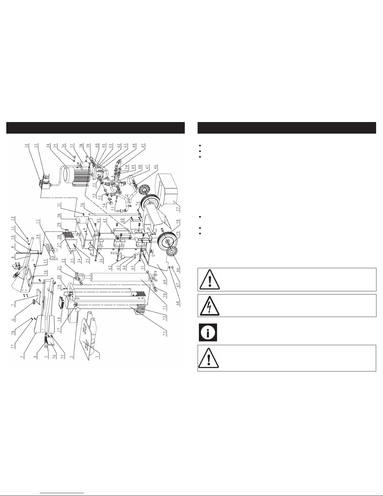
PARTS LIST
No. Description SIP Part No.
1 Work Table WD03-00091
2 Round Cover WD03-00092
3 Operate Handl e WD03- 00093
4 Lever Handle WD03-00094
5 Right Guard Assy WD03-00095
6 Knob WD0 3-00096
7 Clamping Fork (Right) WD03-00097
8 Left Guard Assy WD03-00098
9 Control Lever Shaft WD03-00099
10 Nut WD03-00100
11 Washer WD03 -00101
12 Hex Bolt WD03-00102
13 Control Link Plate WD03-00103
14 Fork WD03-00104
15 Locknut M8 WD03-00105
16 Clamping Fork (Left) WD03-00106
17 Knob WD03-00107
18 Square Cover WD03-00108
19 Nut WD03-00109
20 Draw Rod WD03-00110
21 Pin WD03-00111
22 Circlip WD03-00112
23 Plastic Insert 1 WD03-00113
24 Plastic Insert 4 WD03-00114
25 Screw M6x16 WD03-00115
26 Locknut M4 WD03-00116
27 Plastic Insert 2 WD03-00117
28 Plastic Insert 3 WD03-00118
29 Screw M6x10 WD03-00119
30 Stop Limit Plate WD03-00120
31 Nut M16 WD03-00121
32 Switch WD03-00122
33 Screw M4x6 WD03-00123
34 Motor WD03-00124
35 Washer WD03 -00125
36 Bolt M10x30 WD03-00126
37 Junction Box WD03-00127
38 Hose Clamp WD03-00128
Page 5
20
EXPLODED DIAGRAM
5
SAFETY INSTRUCTIONS….cont
dry area, out of reach of children.
Do not unplug the log splitter to switch it off - always use the on/off switch.
Never stand on the log splitter.
DO NOT dismantle or tamper with the log splitter, as this may be dangerous and will
invalidate the warranty.
If a problem with the log splitter is experienced, or if the mains lead or plug become
damaged, contact your distributor for repair.
If the log splitter is to be used on business premises - ensure that all local and national
regulations are followed concerning the use of portable appliance at work.
WARNING: Risk of Electric Shock!
Use only the electrical power (voltage and frequency) specified on the model plate
of the log splitter. If in doubt contact the manufacturer.
Use only a three-prong, grounded / earthed mains supply.
ALWAYS unplug the log splitter when not in use.
Safety Symbols Used Throughout This Manual.
Danger / Caution: Indicates risk of personal injury and/or the possibility of
damage.
Warning: Risk of electrical injury or damage!
Note: Supplementary information.
CAUTION: The warnings and cautions mentioned in this user manual can
not cover all possible conditions and situations that may occur. It must be
understood by the operator that common sense and caution are factors
which cannot be built into this product, but must be applied.
Page 6
6
WARNING! It is the responsibility of the owner and the operator to read, understand
and comply with the following:
You must check all electrical products, before use, to ensure that they are safe.
You must inspect power cables, plugs, sockets and any other connectors for wear or
damage.
You must ensure that the risk of electric shock is minimised by the installation of appropriate safety devices; A residual current circuit Breaker (RCCB) should be incorporated
in the main distribution board. We also recommend that a residual current Device
(RCD) is used. It is particularly important to use an RCD with portable products that are
plugged into a supply which is not protected by an RCCB. If in any doubt consult a
qualified electrician.
Connecting to the power supply:
This SIP log splitter is fitted with a standard 230v ~ 13 amp type plug. Before using the
log splitter, inspect the mains lead and plug to ensure that neither are damaged. If
any damage is visible have the log splitter inspected / repaired by a suitably qualified person. If it is necessary to replace the plug a heavy duty impact resistant plug
would be preferable.
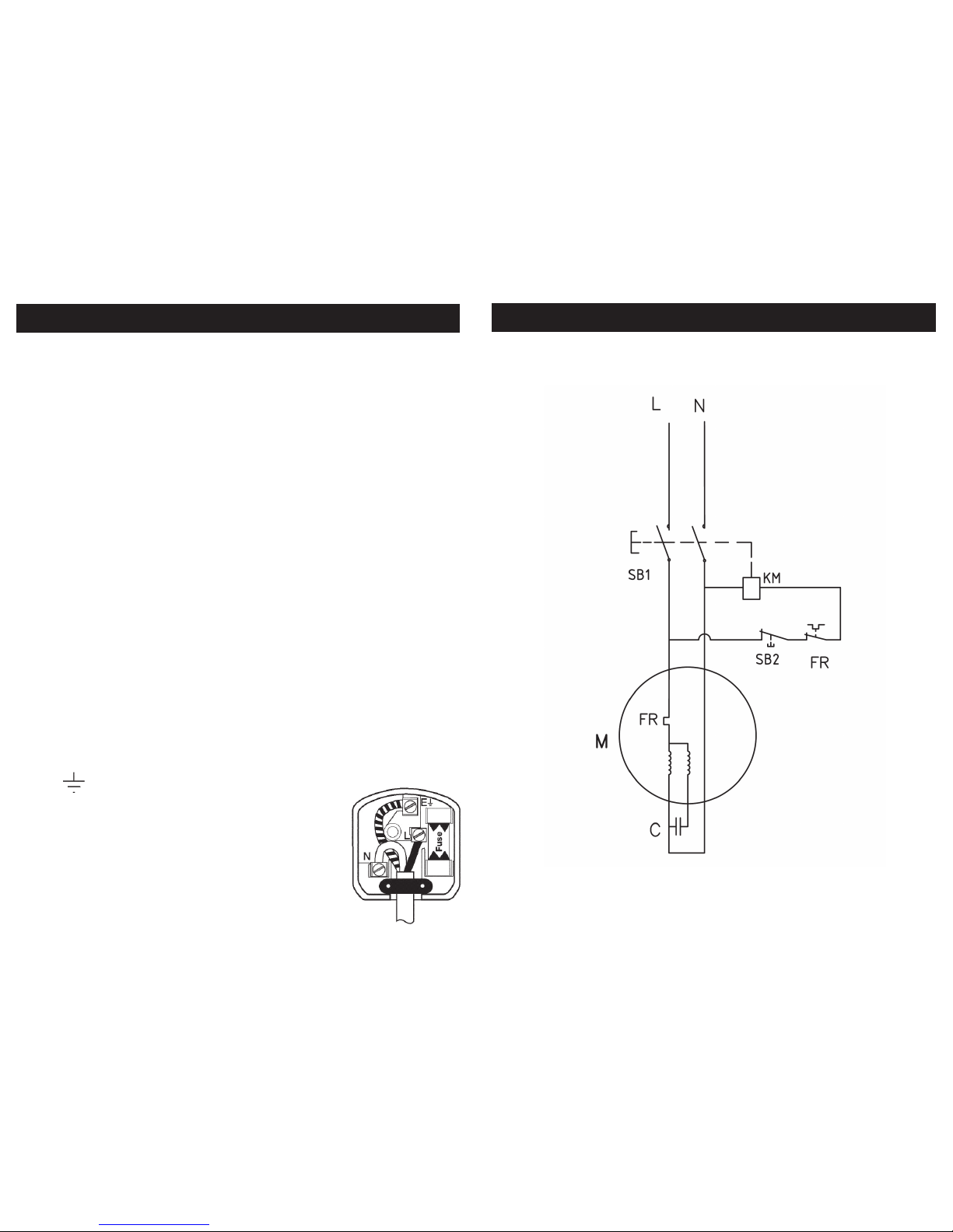
Yellow / green Earth
Blue Neutral
Brown Live
As the colours of the wires may not correspond with the markings in your plug, proceed as follows: The wire which is coloured blue, must be connected to the terminal
marked with N or coloured black. The wire which is coloured brown, must be connected to the terminal, which is marked L or coloured red. The wire which is coloured yellow / green should be connected to the terminal which is coloured the same or
marked
Always secure the wires in the plug terminal carefully and tightly.
Secure the cable in the cord grip carefully.
The wires for the plug are coloured in the following way:
ELECTRICAL CONNECTION
19
WIRING DIAGRAM
Page 7
18
18
MAINTENANCE INSTRUCTIONS….cont
Sharpening The Wedge:
This log splitter is equipped with reinforced splitting wedge with a blade that is specially
treated. After long periods of operation, and when required, sharpen the wedge using
a fine-toothed file removing any burrs or flat spots on the edge.
Motor does not
start
No current in the socket.
Electrical extension line defective.
Switch or capacitor defective.
Check mains fuse.
Unplug, Check and replace.
Replace
Incorrect motor
rotation direction.
Incorrect connection
Change pole switching device in the plug with a screw
driver.
Reverse polarity by electrician.
Log splitter does
not work while motor running.
Valve is not opened owing to
the connection parts loosening.
Control levers or connection
parts bent.
Low hydraulic oil level.
Check and tighten the parts.
Repair the bent parts.
Check and refill hydraulic oil.
Log Splitter works
with abnormal vibration and noise.
Low hydraulic oil level. Check and refill oil level.
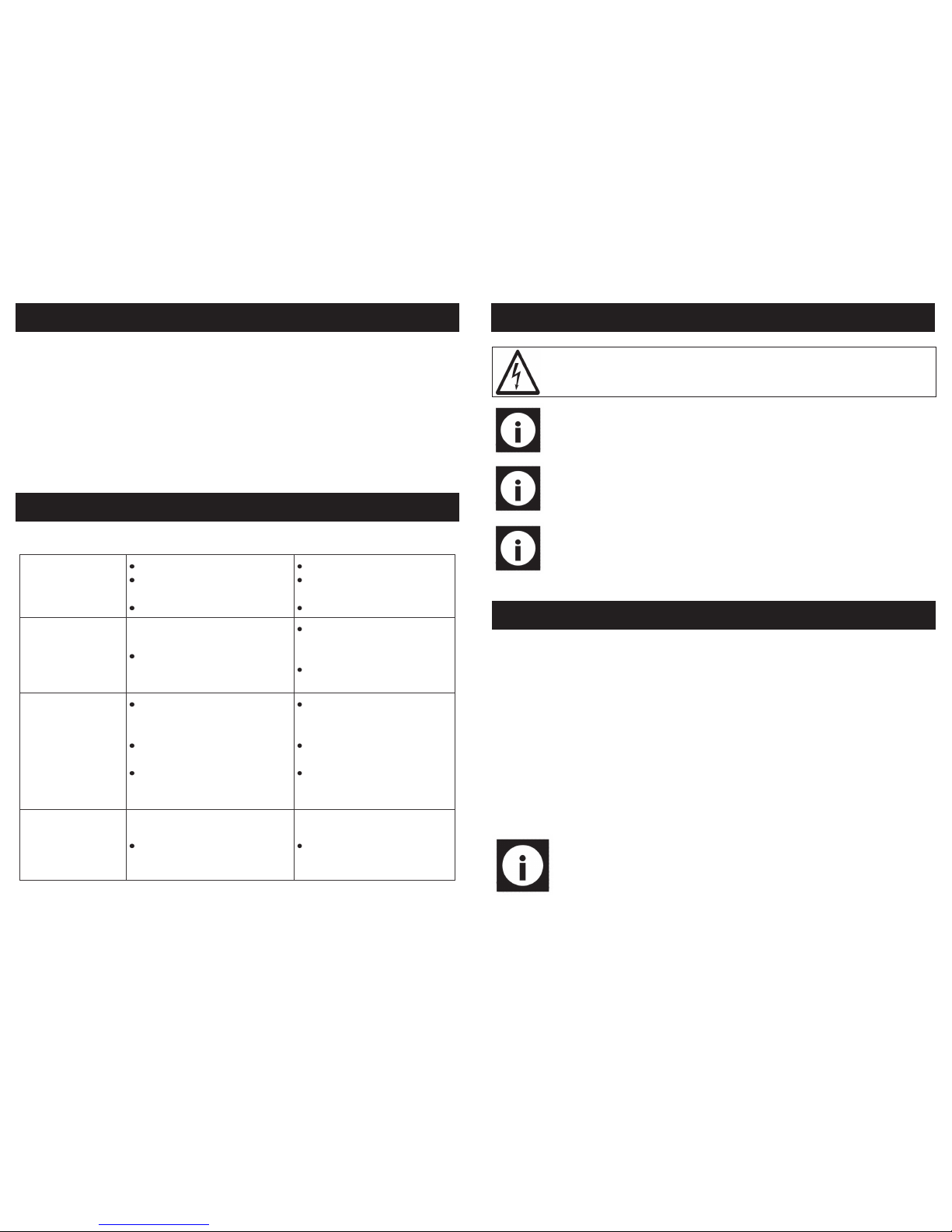
TROUBLESHOOTING
7
Note: Always ensure the mains supply is of the correct voltage and the cor-
rect fuse protection is used. In the event of replacing the fuse always replace the fuse with the same value as the original.
Warning: Never connect live or neutral wires to the earth terminal of the plug.
Only fit an approved plug with the correct rated fuse. If in doubt consult a qualified electrician.
ELECTRICAL CONNECTION….cont
Note: If an extension lead is required in order to reach the mains supply;
ensure that this too is rated for the correct voltage and fuse rating.
Note: The cross section of the extension lead should be checked so that it is
of sufficient size so as to reduce the chances of voltage drops.
GUARANTEE
Guarantee:
This SIP log splitter is covered by a 12 month parts and labour warranty covering failure
due to manufacturers defects. This does not cover failure due to misuse or operating
the machine outside the scope of this manual - any claims deemed to be outside
the scope of the warranty may be subject to charges Including, but not limited to
parts, labour and carriage costs. Consumable items such as fuses and oil are not
covered by the warranty.
In the unlikely event of warranty claims, contact your distributor as soon as possible.
Proof of purchase will be required before any warranty can be honoured.
Note: Proof of purchase will be required before any warranty can be honoured.
Page 8
8
UNPACKING YOUR LOG SPLITTER
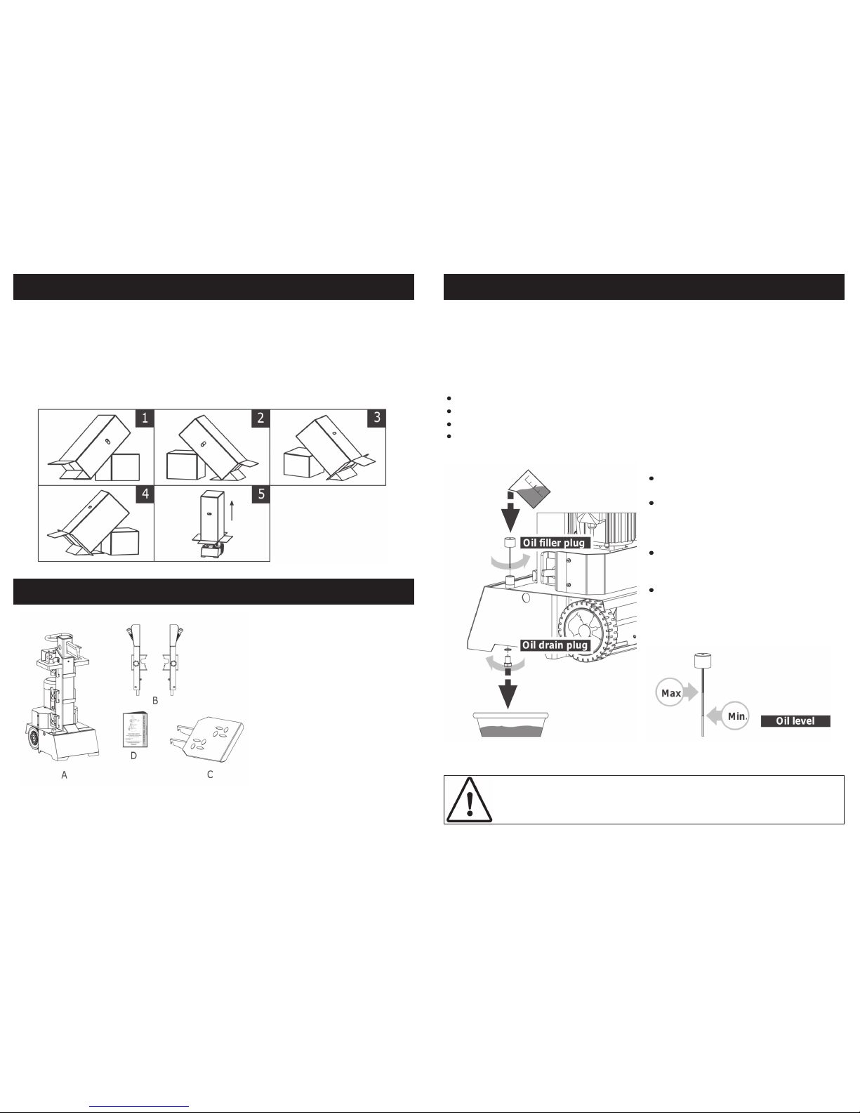
IMPORTANT: At least 2 people are required to unpack the log splitter package.
Take the following steps to put the log splitter onto the ground and remove the packaging by tipping every side of the carton by 45 degrees and opening the corresponding flap. Make sure to put block (B) supporting the log splitter package (A) at the point
a little higher than the middle. The other side of block (B) shall be against steady object, such as a wall, see below diagram.
CONTENTS AND ACCESSORIES
A. Log splitter frame.
B. Control levers.
C. Support table.
D. Manual
If any items are missing or damaged, contact your distributor immediately.
B B
B
A
A
A
17
MAINTENANCE INSTRUCTIONS
Replacing The Hydraulic Oil:
The hydraulic system is a closed system with an oil tank, oil pump and control valve,
check the oil level regularly with the dipstick, low oil levels can damage the oil pump,
oil level should measure approx. 1-2 cm lower than the upper surface of the oil tank,
the oil should be completely replaced every year.
Make sure moving parts are fully stopped and the log splitter is unplugged.
Make sure that no dirt or debris finds its way into the oil tank.
Collect used oil and responsibly recycle.
Following an oil change, activate the log splitter a few times without actually
splitting.
CAUTION: Check the dipstick to determine the maximum and minimum of
the oil level, low oil can damage the oil pump, overfilling can result in excessive temperature in the hydraulic transmission system.
Use a drain pan to aid in the removal of all used oil and particles.
Remove the oil drain plug to drain
oil from the hydraulic transmission
system, examine the oil for fillings
as a precaution to future problems.
After the oil has been completely
drained from the machine, reinstall
drain plug.
Add the hydraulic transmission system with recommended oil
through filler plug opening.
Page 9
16
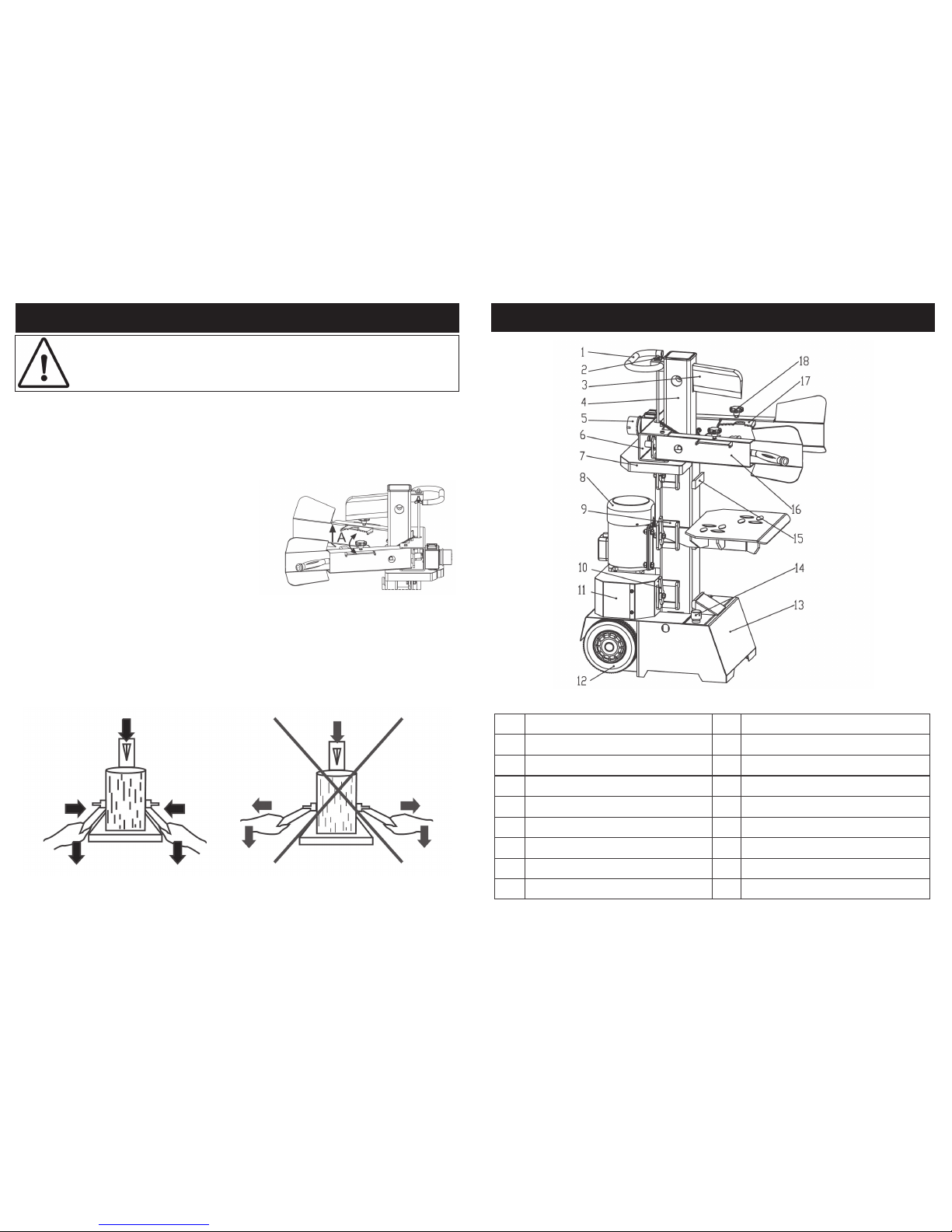
9. Place the log onto the support table vertically and sitting flat on the support table,
be sure the wedge and support table will contact the log squarely on the ends,
never attempt to split a log at an angle.
10. Adjust the log holders (A) according to
the diameter of the log to obtain most
comfortable control lever angle.
OPERATING INSTRUCTIONS….cont
11. Hold the log with clamping brackets closely in the control lever guards (as shown
in below diagram), lower the levers to start the splitting, releasing either lever stops
the motion of the splitting wedge, releasing both handles to return the splitting
wedge to the upper position.
12. Stack as you work, this will provide a safer work area, by keeping it uncluttered,
and avoid the danger of tripping over the mains lead or damaging the lead.
CAUTION: Break the log in the direction of its growing grain, do not place
log across the log splitter for splitting, it may be dangerous and may seriously damage the machine.
9
GETTING TO KNOW YOUR LOG SPLITTER
1 Handle 10 Table lock down hook
2 Ram travel adjusting rod 11 Base cover
3 Split wedge 12 Wheels
4 Ram 13 Base
5 On/Off switch 14 Oil tank cover / air bleeder
6 Control levers connection bracket 15 Front bracket for support table
7 Top motor shield 16 Control levers
8 Motor 17 Adjustable log holder
9 Side bracket for support table 18 Log holder adjusting knob
Page 10
10
GETTING TO KNOW YOUR LOG SPLITTER….cont
Always operate your log splitter on dry, solid, level ground. Never operate
your log splitter on slippery, wet, muddy, or icy surfaces. The location you
choose should be free from any tall grass or other interferences. There
should be plenty of room for handling. Keep your work area clean and
tidy as much as possible. Cluttered areas invite injuries. To avoid tripping,
do not leave tools, logs, or other components laying around the work area. Do not use the log splitter in wet or damp areas or expose it to rain. Do
not use it in areas where fumes from paint, solvents or flammable liquids
pose a potential hazard.
Any log splitter may throw foreign objects into the eyes, this can cause permanent eye damage, always wear safety goggles, everyday eyeglasses
have only impact resistant lenses, they are not safety glasses.
Take used oil to an authorized collection point or follow the stipulations in
the country where the log splitter is used. Do not discharge into drains, soil
or water.
Unplug when not in use, before making adjustments, changing parts,
cleaning, or working on the log splitter.
Check your log splitter before turning it on. Keep guards in place and in
working order. Form a habit of checking to see that any adjusting tools
etc. are removed from machine and work area before turning it on. Replace damaged, missing or failed parts before operating the log splitter.
Make sure all nuts, bolts, screws, hydraulic fittings, hose clamps, etc. are
securely tightened. Always check the oil level in the hydraulic oil tank. Never operate your log splitter when it is in need of repair or is in poor mechanical condition.
Read and understand the owner’s manual and labels affixed to the log
splitter. learn its application and limitations as well as the specific potential
hazards peculiar to it.
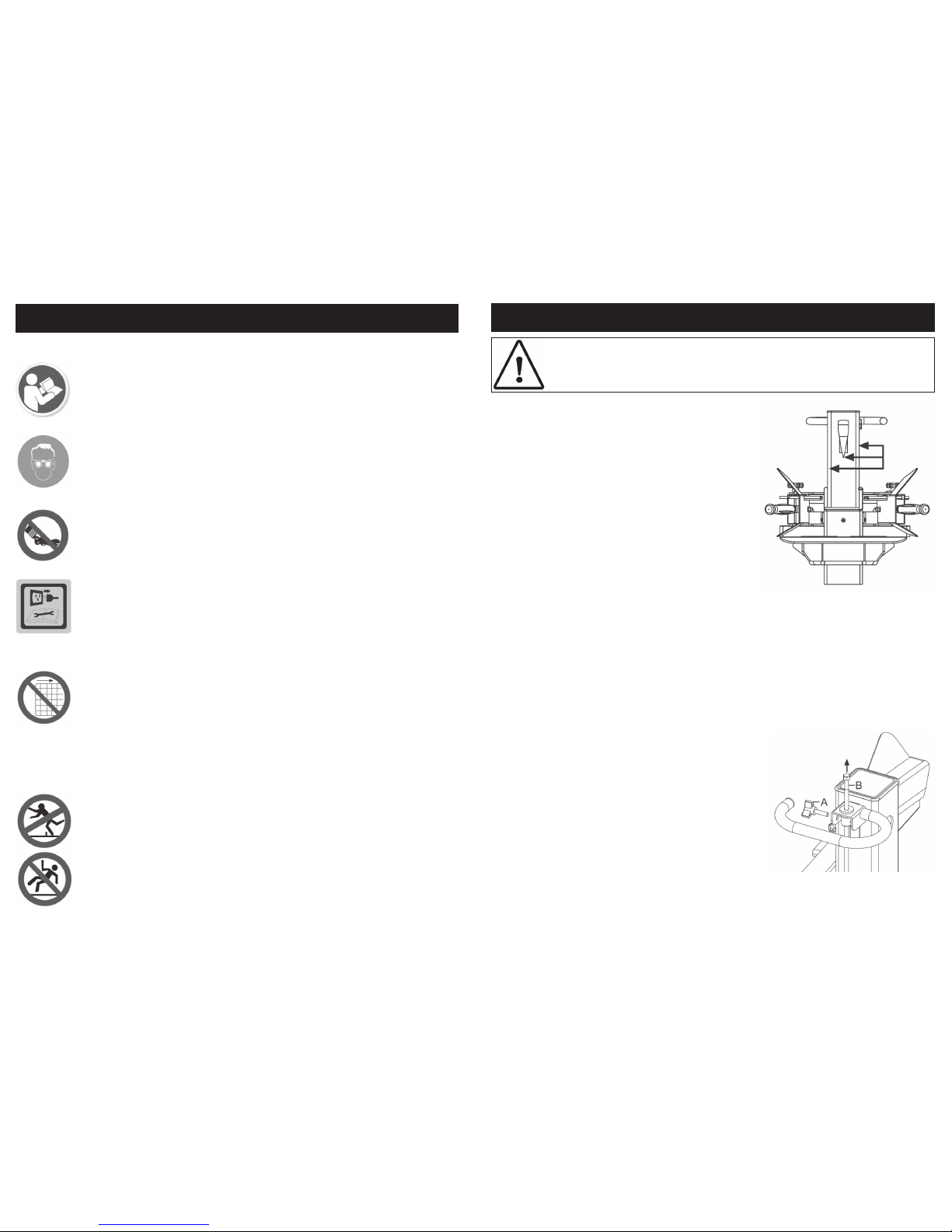
Warning Labels Attached To The Log Splitter:
15
Grease
3. Apply a thin coat of grease to the surfaces of
the ram as shown.
4. Route the mains lead from the power source to
the splitter in a way that safeguards against tripping on the cord.
5. Loosen hydraulic oil filler cap a few turns whenever the splitter is being used (retighten when
you have finished using the log splitter).
6. Start the log splitter and leave running for about
15 minutes to preheat the hydraulic oil.
7. Before initial operation, ensure the two-handed
operation is correctly functioning by following
steps:
OPERATING INSTRUCTIONS….cont
a) Lower both control levers, the splitting wedge will lower.
b) Release either of the levers, the splitting wedge should remain in the original
lowered position.
c) Release both levers, the ram should rise to the highest position automatically.
It is possible to set the height of the cutting wedge to match the logs to be cut; this will
reduce down time as the ram will not have to return fully to the top of its stroke.
8. To set the wedge ram stroke, take the following
steps:
a) Move the splitting wedge to desired position,
the upper position of the ram wedge travel
should be about 3-5cm over the logs to be
split.
b) Release one of the control levers or switch off
motor.
c) Loosen the setscrew (A), raise the adjusting rod
(B) until you feel resistance then tighten the
setscrew (A).
d) Release both control levers or switch on motor.
e) Check the upper position of the splitting
wedge.
CAUTION: Do not attempt to split logs that are too “green.” Dry, seasoned
logs split much more easily, and will not jam as frequently as green wood.
Page 11
14
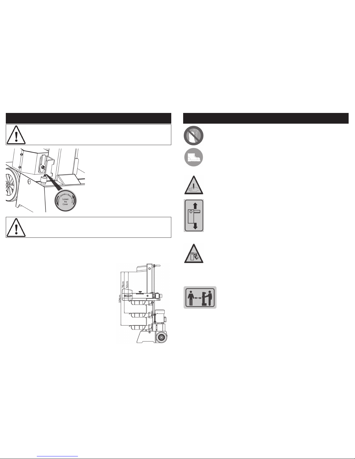
OPERATING INSTRUCTIONS….cont
1. Plan your work site; work safely and save effort by planning your work area before
hand. Have your logs positioned where they can be easily reached, have a site located to stack the split wood or load it onto a nearby truck or other carrier.
2. Set the support table (as shown on page 13) to the
correct position for the length of logs to be split. The
log splitter accommodates logs up to 104cm in
length.
Bleed the air out of the hydraulic system
before starting the log splitter, and keep the
cap open during operation.
The hydraulic oil filler cap should be loosened by some rotations until air can flow
into and out of the oil tank smoothly. Air flow
through the oil tank filler should be detectable during the operation.
IMPORTANT: Always open the hydraulic oil filler cap before using the log
splitter and keep it open during operation. When not in operation ensure
the hydraulic oil filler cap is fully closed.
CAUTION: Failing to ope n and leave the hydraulic oil filler cap ope n when i n use will lock the
sealed air in the hydraulic system. Such continuous air com pression will blow out the seals of
the hydraulic system, this will cause permanent damage to the log splitter and void t he warranty.
11
GETTING TO KNOW YOUR LOG SPLITTER….cont
Allow only one person to load and operate the log splitter. Always
keep bystanders, including visitors, children and pets away from the
work area, especially when the log splitter is under operation. Only
the operator should stand near the machine. Never use another
person to help you with freeing a jammed log. No one under the
age of 16 should be allowed to operate the log splitter. Any individual under the age of 18 should have the necessary training skills to
perform the functions properly and safely and should always be
under the supervision of an adult.
When the ram of the log splitter is in the return mode, keep your hands off
the machine – the log splitter is designed to automatically stop when the
cylinder is fully retracted. Keep you hands away from splits and cracks
which open in the log. They may close suddenly and crush or amputate
your hands.
Do not straddle or reach across the splitting area when operating the log
splitter. Never pile logs to be split in a manner that will cause you to reach
across the log splitter. Only use your hands to operate the control levers.
Never use your foot, knee, a rope, or any other extension device. Always
pay full attention to the movement of the wedge ram. Never attempt to
load your log splitter while the ram is in motion. Keep hands out of the way
of all moving parts. Never try to split two logs on top of each other. One of
them may fly up and cause injury.
Do not wear loose clothing, gloves, neckties or jewellery (rings, wrist watches). They can be caught in moving parts. Non-skid footwear is recommended during operation. Wear protective hair covering to contain long
hair, preventing it from getting caught in the machinery.
Page 12
12
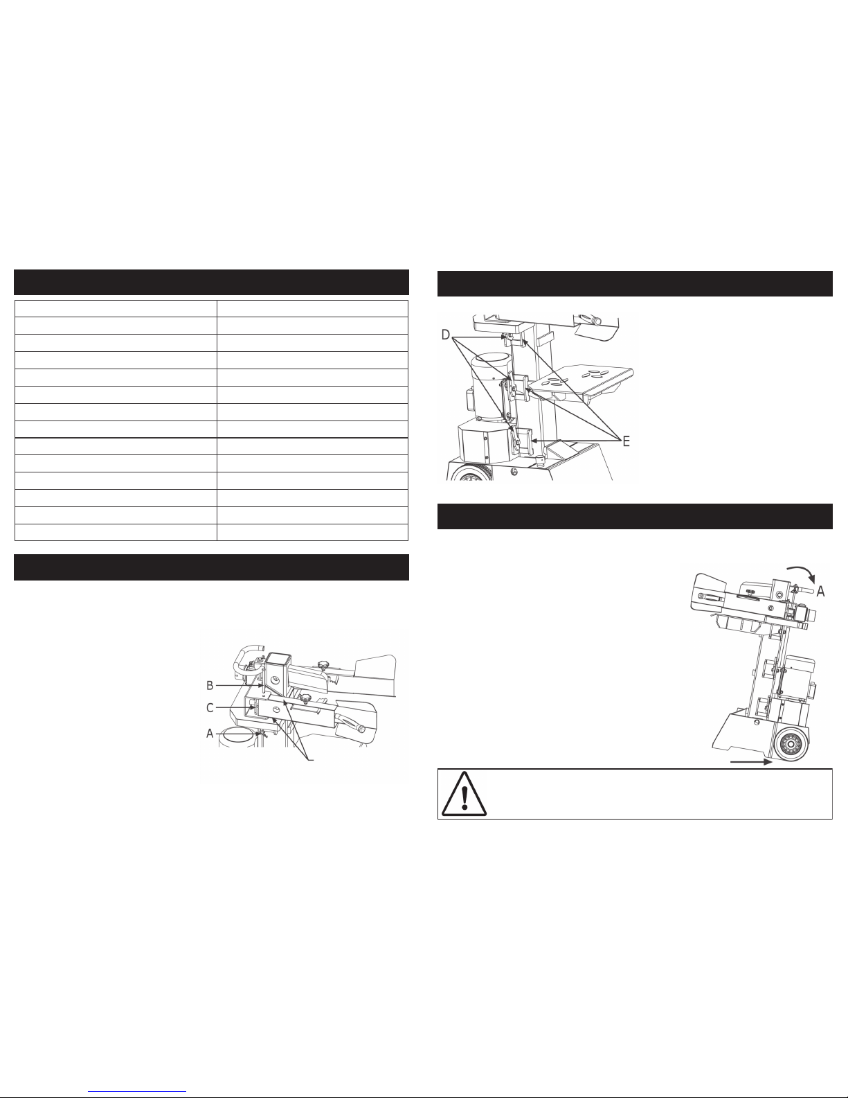
TECHNICAL SPECIFICATIONS
ASSEMBLY INSTRUCTIONS
a. Locate both control levers.
b. Remove spring pin (A) from one
side of the machine to release the
lock pin (B).
c. Apply a thin coat of grease onto
the control lever, as shown on diagram.
d. Insert the control lever into the slot
of the connection bracket (C).
e. Put the lock pin (B) through the top
hole of the connection bracket (C),
making sure that the holes on the
connection bracket and control
lever line up.
f. Once the lock pin (B) is all the way
through the bottom of the connection bracket, replace spring pin (A)
to secure to lock pin (B).
g. Repeat on the opposite side.
Grease
Part No. 01977
Input 230v ~ 50Hz, 3000w
Log Capacity - Ø 120 mm - 320 mm
Log Capacity - length 1040 mm / 780 mm / 520 mm
Splitting Force 7 ton
Hydraulic Pressure 22 Mpa
Hydraulic Oil Capacity 5 litre
Ram Travel 480 mm
Forward Speed 3.9 cm/sec
Retract Speed 14.5 cm/sec
Noise Level - No Load 80.1 dba
Noise level - Full Load 92.5 dba
Dimensions ( HxWxL) 1470 x 930 x 830mm
Weight 115 kg
13
There are 3 positions available for the
support table for different splitting lengths
104cm / 78cm / 52cm.
Ensure that the lock down hooks (D) are
in the vertical position.
Slide the support table into the frame
brackets (E), ensuring that they hook under the top of the frame brackets (E). Turn
the lock down hooks (D) to the horizontal
position to secure the support table in
place.
OPERATING INSTRUCTIONS
The log splitter is equipped with 2 wheels to allow it
to be moved to and around the work area.
Ensure the oil filler cap is fully closed (see page
14) before moving the log splitter.
To move the log splitter:
Stand behind the log splitter.
Grip the handle (A)
Tilt the log splitter slightly towards you and move to
desired location.
ASSEMBLY INSTRUCTIONS ….cont
CAUTION: If using a crane: lay hoist sling around the bottom housing. Never try to lift the log splitter at the Handle (A).
Moving The Log Splitter:
 Loading...