

Page 1
28
FOR HELP OR ADVISE ON THIS PRODUCT PLEASE CONTACT YOUR DISTRIBUTOR,
OR SIP DIRECTLY ON:
TEL: 01509500400
EMAIL: [email protected] or [email protected]
www.sip-group.com
Please dispose of packaging for the product in a responsible
manner. It is suitable for recycling. Help to protect the
environment, take the packaging to the local amenity tip
and place into the appropriate recycling bin.
Never dispose of electrical equipment or batteries in with
your domestic waste. If your supplier offers a disposal facility please use it or alternatively use a recognised re-cycling
agent. This will allow the recycling of raw materials and help
protect the environment.
Ref: 030413
1
4” x 8”
Belt Disc Sander
Please read and fully understand the instructions in
this manual before operation. Keep this manual
safe for future reference
01946
Page 2
2
27
Declaration of Conformity
We
SIP (Industrial Products) Ltd
Gelders Hall Road
Shepshed
Loughborough
Leicestershire
LE12 9NH
England
As the manufacturer's authorised representative within the EC
declare that the
4”x 8” Belt / Disc Sander - SIP Part. No. 01946
Conforms to the requirements of the following directive(s), as indicated.
2006/42/EC Machinery Directive
2006/95/EC Low Voltage Directive
2004/108/EC EMC Directive
2008/35/EC RoHS Directive
And the following harmonised standard(s)
EN 55014-1:2006+A1+A2
EN 55014-2:1997+A1+A2
EN 61000-3-2:2006+A1+A2
EN 61000-3-3:2008
Signed: …………………………………...
Mr P. Ippaso - Director - SIP (Industrial Products) Ltd
Date: 06/03/2013.
DECLARATION OF CONFORMITY
Page 3

26
NOTES
3
CONTENTS
Page No. Description
4 Safety instructions
7 Electrical connections
8 Guarantee
9 Technical specifications
10 Getting to know your belt disc sander
11 Contents and Accessories
11 Assembly instructions
14 Adjustments
15 Operating instructions
17 Care and maintenance
20 Troubleshooting
21 Exploded diagram
22 Parts list
26 Notes
27 Declaration on conformity
Page 4
4
SAFETY INSTRUCTIONS
IMPORTANT: Please read the following instructions carefully, failure to do so could
lead to serious personal injury and / or damage to the Belt Disc Sander.
When using your belt disc sander, basic safety precautions should always be followed
to reduce the risk of fire, electric shock, personal injury and / or damage to the belt
disc sander. Read all these instructions before operating the belt disc sander and
save this user manual for future reference.
SIP recommends that this belt disc sander should not be modified or used for any application other than that for which it was designed. If you are unsure of its relative applications do not hesitate to contact us and we will be more than happy to advise
you.
The sander is only designed for sanding wood or wood composites - It is not designed
for sanding metals.
KNOW YOUR BELT DISC SANDER: Read and understand the owner's manual and labels
affixed to the belt disc sander. Learn its applications and limitations, as well as the potential hazards specific to it.
DO NOT USE THE BELT DISC SANDER IN DANGEROUS ENVIRONMENTS: Do not use your
belt disc sander in damp or wet locations, or expose it to rain. Always provide adequate space around the belt disc sander.
KEEP CHILDREN AND UNTRAINED PERSONNEL AWAY FROM THE WORK AREA: All visitors
should be kept at a safe distance from the work area.
STAY ALERT: Always watch what you are doing and use common sense.
DISCONNECT THE BELT DISC SANDER FROM THE MAINS SUPPLY: When not in use.
DO NOT ABUSE THE MAINS LEAD: Never pull the mains lead it to remove the plug from
the mains socket. Keep the mains lead away from heat, oil and sharp edges. If the
mains lead is damaged, it must be replaced by the manufacturer or its service agent
or a similarly qualified person in order to avoid unwanted hazards.
HAVE YOUR BELT DISC SANDER REPAIRED BY A QUALIFIED PERSON: The belt disc sander
is in accordance with the relevant safety requirements. Repairs should only be carried
out by qualified persons using original spare parts, otherwise this may result in considerable danger to the user.
DANGER! Check that the belt disc sander is in sound condition and good working
order. Take immediate action to repair or replace damaged parts.
USE RECOMMENDED PARTS ONLY - Unapproved parts may be dangerous and will
invalidate the warranty.
WARNING! Only operate on a level and stable surface.
WARNING! Do not allow untrained persons to operate the machine and do not oper-
ate the machine without all covers etc. correctly fitted.
WARNING! RISK OF ELECTRIC SHOCK. Do not expose the belt disc sander to water
spray, rain, dripping water or moisture of any kind.
Do not move or handle the machine when it is running.
25
106 Capacitor 12μF 450V WD01-00100
107 Hex screw M6×25 WD01-00101
108 Capacitor support 2 WD01-00102
109 Capacitor 100μF 250V WD01-00103
110 Disc plate WD01-00104
111 Flat washer M4 WD01-00105
112 Hex screw M5×8 WD01-00106
113 Dust bag WD01-00107
114 Position shaft WD01-00108
115 Miter gauge pointer WD01-00109
116 Hex nut M8 WD01-00110
117 Dust box cover WD01-00111
121 Scale label left WD01-00112
122 Scale label right WD01-00113
123 Rotation label WD01-00114
124 Belt tension label WD01-00115
125 hex wrench WD01-00116
126 Scale label WD01-00117
127 Spring washer D40 WD01-00118
128 Spring washer M4 WD01-00119
129 Tooth lock washer M4 WD01-00120
130 Bearing bushing WD01-00121
131 Spring pin 4X22 WD01-00122
132 Spring washer M6 WD01-00123
133 Disc work table Knob WD01-00124
134 Hex screw M5×12 WD01-00125
135 Screw M4×10 WD01-00126
136 Spring washer M5 WD01-00127
137 Screw M5×10 WD01-00128
138 Flat washer M5 WD01-00129
139 Lock washer M4 WD01-00130
140 Flat washer M4 WD01-00131
141 Index plate scale WD01-00132
142 Support locating plate WD01-00133
143 Flat washer M8 WD01-00134
PARTS LIST….cont
Page 5
24
69 Screw M4X12 WD01-00068
70 Belt exhaust WD01-00069
71 Collector mounting shaft WD01-00070
72 Hex screw M5×20 WD01-00071
73 Belt mounting plate WD01-00072
74 End cap WD01-00073
75 Mains lead WD01-00074
76 Strain relief WD01-00075
77 Preventer plate WD01-00076
79 Relay WD01-00077
81 Left end cap WD01-00078
82 Key 5X5X15 WD01-00079
83 Washer WD01-00080
84 Screw M6x16 WD01-00081
85 Sanding disc 150 grit 06837
85 Sanding disc 120 grit 06839
85 Sanding disc 60 grit 06841
86 Disc cover WD01-00082
87 Screw M4×10 WD01-00083
88 Angle pointer WD01-00084
89 Disc left support WD01-00085
90 Handle assembly WD01-00086
91 Disc work table WD01-00087
92 Miter gauge bar WD01-00088
93 Miter gauge WD01-00089
94 Disc right support WD01-00090
95 Bearing 6203RZ WD01-00091
96 Rotor WD01-00092
97 Screw M5×180 WD01-00093
98 Stator WD01-00094
99 Hex nut M5 WD01-00095
100 Motor cover WD01-00096
103 Switch WD01-00097
104 Tube connector WD01-00098
105 Capacitor support1 WD01-00099
PARTS LIST….cont
5
Do not leave the machine unattended when in use. Switch the machine off and
unplug from the mains supply before leaving the work area.
Do not allow children or animals near the belt disc sander, particularly when in use.
Ensure that the belt disc sander is correctly turned off when not in use and store in a
safe, dry area, out of reach of children.
Do not unplug the belt disc sander to switch it off - always use the on/off switch.
ALWAYS locate belt disc sander on a stable and level surface.
Never stand on the belt disc sander.
DO NOT dismantle or tamper with the belt disc sander, as this may be dangerous
and will invalidate the warranty.
Always ensure that the belt / disc sander is turned off and that the mains lead is removed from the supply during all cleaning and maintenance procedures, and
when changing the disc or tracking / changing the belt.
WARNING: Risk of Electric Shock!
Use only the electrical power (voltage and frequency) specified on the model plate
of the belt disc sander. If in doubt contact the manufacturer.
Use only a three-prong, grounded outlet and where required.
ALWAYS unplug the belt disc sander when not in use.
Always wear approved eye protection.
Always wear respiratory protection.
it is advisable to ensure the operator as well as those in the area wear ear protection,
particularly during extended periods of use.
Never wear gloves, neck-ties, jewellery or loose clothing, and always contain long
hair during operation.
Support the work-piece with the mitre gauge, backstop or worktable.
Maintain 1/16” maximum distance between table and sanding belt / disc.
Avoid kickback by sanding in accordance with the directional arrows.
Always mount the sander securely on a firm level surface.
Do not expose the sander to rain or moisture.
Always disconnect the sander from the mains supply before making repairs or adjustments.
Do not move or handle the machine when it is running.
If a problem with the belt disc sander is experienced, or if the mains lead or plug become damaged, contact your distributor for repair.
If the charger is used in a place of work all rules and laws etc. relating to the use of
portable electrical appliances should be followed.
SAFETY INSTRUCTIONS….cont
Page 6
6
CAUTION: The warnings and cautions mentioned in this user manual can not cov-
er all possible conditions and situations that may occur. It must be understood by
the operator that common sense and caution are factors which cannot be built
into this product, but must be applied.
When using the sander always ensure the operator as well as those in the
area wear eye protection.
Sanding operations will cause dust to become airborne with the potential to be
highly toxic; always wear a face mask during these operations, as well as ensuring
the area is well ventilated. It is also highly recommended to use a dust collector to
reduce airborne particles.
When using this sander, it is advisable to ensure the operator as well as
those in the area wear ear protection, particularly during extended periods
of use.
Safety Symbols Used Throughout This Manual.
Danger / Caution: Indicates risk of personal injury and/or the possibility of
damage.
Warning: Risk of electrical injury or damage!
Note: Supplementary information.
Operational Safety.
SAFETY INSTRUCTIONS….cont
23
35 Pin 5×10 WD01-00035
36 Screw M5×25 WD01-00036
37 Belt tracking knob WD01-00037
38 Flat washer M6 WD01-00038
39 Rubber washer WD01-00039
40 Adjust spring WD01-00040
41 Belt frame WD01-00041
42 Tension spring WD01-00042
43 Sleeve WD01-00043
44 Spring washer M12 WD01-00044
45 Bearing 6001RZ WD01-00045
46 Idler shaft WD01-00046
47 Idler pulley WD01-00047
48 Belt tension assembly WD01-00048
49 Hex screw M6×12 WD01-00049
50 Belt working table WD01-00050
51 Big washer M6 WD01-00051
52 Miter gauge Knob WD01-00052
53 Sanding belt 120 grit 07740
53 Sanding belt 60 grit 07744
54 Drive pulley WD01-00053
55 Hex screw M8×12 WD01-00054
56 Collector shaft WD01-00055
57 Screw M5×8 WD01-00056
58 Flat washer M5 WD01-00057
59 Work table angle point WD01-00058
60 Belt frame connect WD01-00059
61 Cord bushing WD01-00060
62 Belt cover WD01-00061
63 Pin 2x10 WD01-00062
64 Spring washer WD01-00063
65 Connection plate WD01-00064
66 Right cover WD01-00065
67 Left cover WD01-00066
68 Small pulley WD01-00067
PARTS LIST….cont
Page 7
22
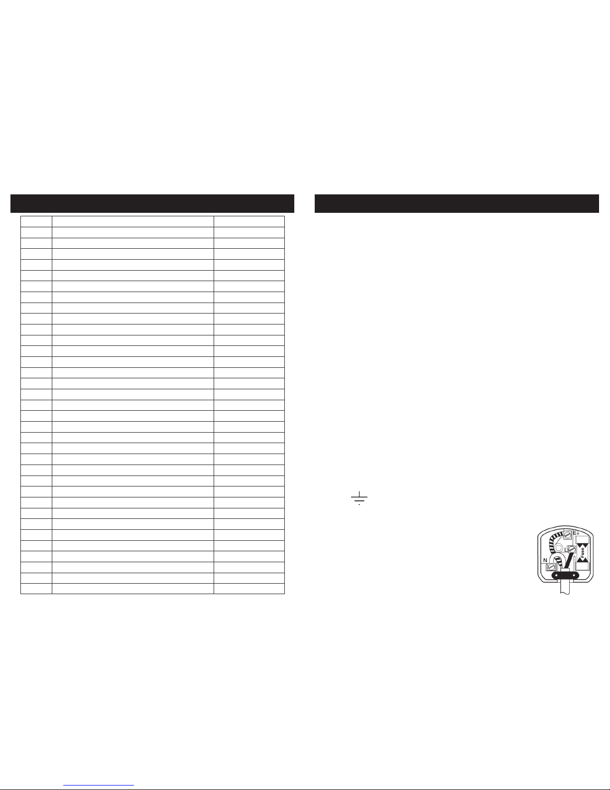
Ref No. Description SIP Part No.
1 Rubber Foot WD01-00001
2 Screw M4×10 WD01-00002
3 Bottom Plate WD01-00003
4 Screw M8×25 WD01-00004
5 Lock washer M8 WD01-00005
6 Flat washer M8 WD01-00006
7 Base WD01-00007
8 Connect tube WD01-00008
9 Big pulley WD01-00009
10 Poly-v- belt WD01-00010
11 Collector bearing 6000RZ WD01-00011
12 Spring washer D26 WD01-00012
13 Screw ST4.2×15 WD01-00013
14 Fan cover WD01-00014
15 Fan WD01-00015
16 Big washer M5 WD01-00016
17 Spring washer M5 WD01-00017
18 Screw M5×16 WD01-00018
19 Fan Housing WD01-00019
20 Screw M5×10 WD01-00020
21 Front cover WD01-00021
22 Dust storage box WD01-00022
23 Screw M5×8 WD01-00023
24 Exhaust cover WD01-00024
25 Dust exhaust WD01-00025
26 Hex nut M6 WD01-00026
27 Bag Clamp WD01-00027
28 Clamp handle WD01-00028
29 Screw M6×40 WD01-00029
30 Tooth lock washer M5 WD01-00030
31 Tension level WD01-00031
32 Sleeve WD01-00032
33 Tension handle WD01-00033
34 Pin 5×8 WD01-00034
PARTS LIST
7
WARNING! It is the responsibility of the owner and the operator to read, understand
and comply with the following:
You must check all electrical products, before use, to ensure that they are safe.
You must inspect power cables, plugs, sockets and any other connectors for wear or
damage.
You must ensure that the risk of electric shock is minimised by the installation of appropriate safety devices; A residual current circuit Breaker (RCCB) should be incorporated
in the main distribution board. We also recommend that a residual current Device
(RCD) is used. It is particularly important to use an RCD with portable products that are
plugged into a supply which is not protected by an RCCB. If in any doubt consult a
qualified electrician.
Connecting to the power supply:
This SIP sander is fitted with a standard 230v ~ 13 amp type plug. Before using the
machine, inspect the mains lead and plug to ensure that neither are damaged. If
any damage is visible have the machine inspected / repaired by a suitably qualified
person. If it is necessary to replace the plug a heavy duty impact resistant plug would
be preferable.
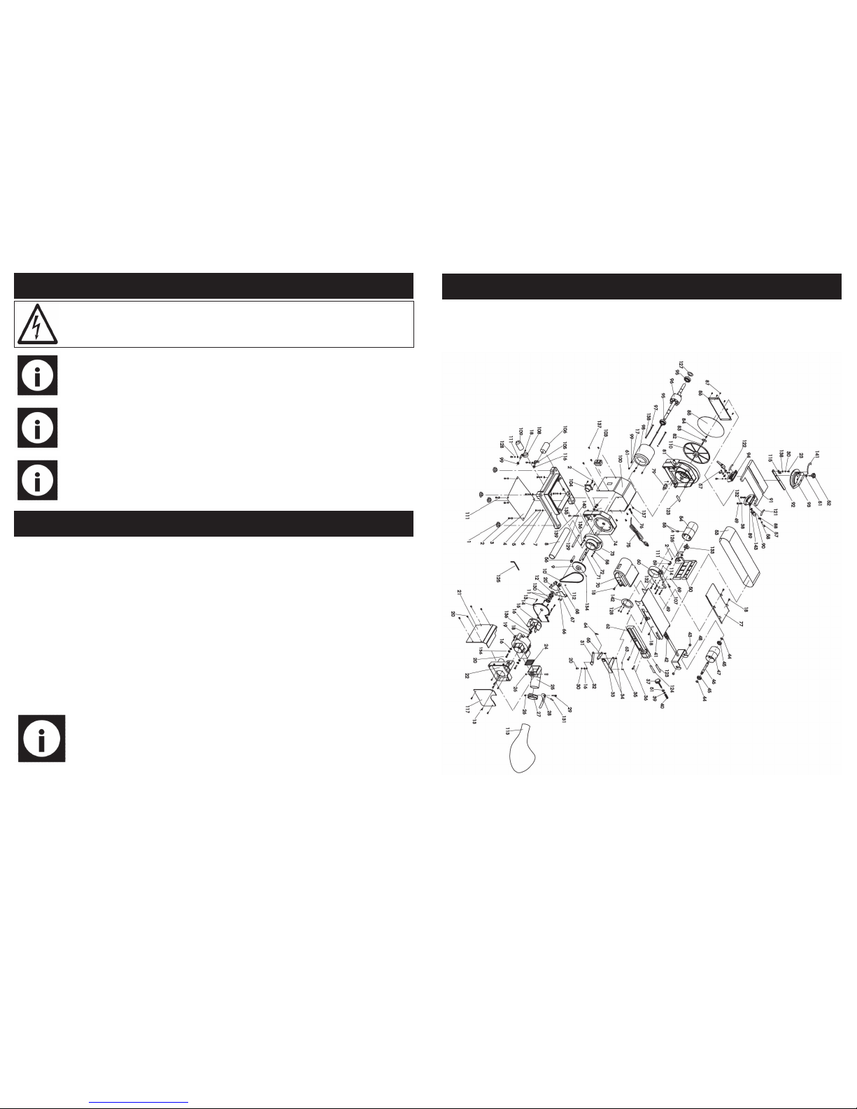
The wires for the plug are coloured in the following way:
Yellow / green Earth
Blue Neutral
Brown Live
As the colours of the wires may not correspond with the markings in your plug, proceed as follows: The wire which is coloured blue, must be connected to the terminal
marked with N or coloured black. The wire which is coloured brown, must be connected to the terminal, which is marked L or coloured red. The wire which is coloured yellow / green should be connected to the terminal which is coloured the same or
marked
Always secure the wires in the plug terminal carefully and tightly. Secure the cable in
the cord grip carefully.
ELECTRICAL CONNECTION
Page 8
8
Note: Always make sure the mains supply is of the correct voltage and the
correct fuse protection is used. In the event of replacing the fuse always
replace the fuse with the same value as the original.
Warning: Never connect live or neutral wires to the earth terminal of the plug. Only
fit an approved plug with the correct rated fuse. If in doubt consult a qualified electrician.
GUARANTEE
Note: Proof of purchase will be required before any warranty can be honoured.
Note: If an extension lead is required in order to reach the mains supply;
ensure that this too is rated for the correct voltage and fuse rating.
Note: The cross section of the extension lead should be checked so that it is
of sufficient size so as to reduce the chances of voltage drops.
ELECTRICAL CONNECTION….cont
Guarantee:
This SIP belt / disc sander is covered by a 12 month parts and labour warranty, covering failure due to manufacturers defects. This does not cover failure due to misuse or
operating the sander outside the scope of this manual - any claims deemed to be
outside the scope of the warranty may be subject to charges including, but not limited to parts, labour and carriage costs. Consumable items such as fuses, sanding
belts and discs are not covered by the warranty.
In the unlikely event of warranty claims, contact your distributor as soon as possible.
Proof of purchase will be required before any warranty can be honoured.
21
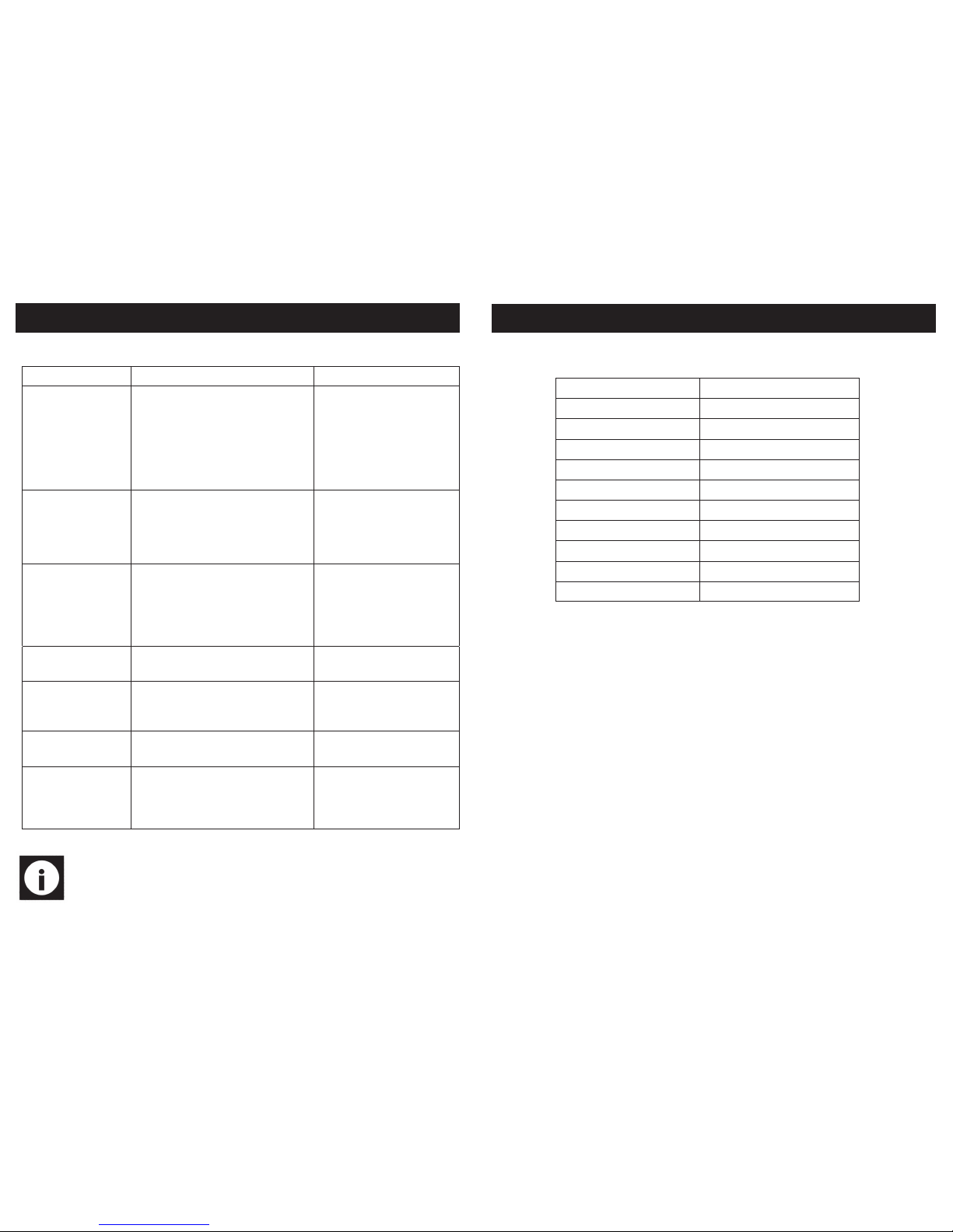
EXPLODED DIAGRAM
Page 9
20
Problem Possible cause Suggested correctiv e action
Motor will not run.
1.Defective or broken ON/OFF switc h.
2.Defective or damaged switch relay.
3.Defective or damaged switch cord.
4.Burned out motor.
5.Blown house fuse.
1-3.Replace all broken or defective parts before using sander.
4.Contact supplier for repair.
5.Replace house fuse. Turn OFF
other appliances and power tools
on the same circuit.
Machine slows down
while sanding.
1.Operator applying too much pressure to
work piece.
2.Dirt on wheels.
3.Worn or stretched belt.
1.Use less pressure in applying
work piece to sanding surface.
2.Clean wheels.
3.Replace pulley belt.
Motor does not develop
full speed.
1.Power line overloaded with lig hts, other
tools, etc.
2.Long/wrong extension lead bei ng used.
3.Incorrect fuses or circuit breakers in power line
1.Reduce the load on power lin e.
2.Replace with correct extensio n
lead.
3.Install correct fuses or circuit
breaker.
Sanding belt runs off
pulleys.
1.Not tracking properly. 1.Adjust tracking (see pg15 tra cking the belt).
Wood burns while sanding.
1.Sanding disc or belt glazed with sap.
2.Excessive pressure being applied t o work
piece.
1.Replace belt or disc.
2.Reduce pressure applied to
work piece.
Motor overheats. 1.Motor overload.
1.Reduce motor load. Allow to
cool off before restarting.
Dust Collection not working.
1.Collection bag is full.
2.Dust exhaust is blocked.
1.Empty collection bag.
2.Turn sander off and unplug.
Remove bag and use a vacu um
to remove sawdust blockage.
Note: Only use original spare parts, the use of non original parts is dangerous and will void your warranty.
TROUBLESHOOTING
9
Model No. 01946
Supply 230v ~ 50Hz
Power 500w (Induction motor)
Belt speed 550m/min
Disc speed 2850rpm
Disc workable tilt 0°-45°
Belt tilt 0°-90°
Disc size 8” (203mm)
Belt size 4” x 36” (100mm x 914mm)
Table size (Sanding disc) 264mm x 150mm
Table size (Sanding bed) 170mm x 125mm
TECHNICAL SPECIFICATIONS
Page 10
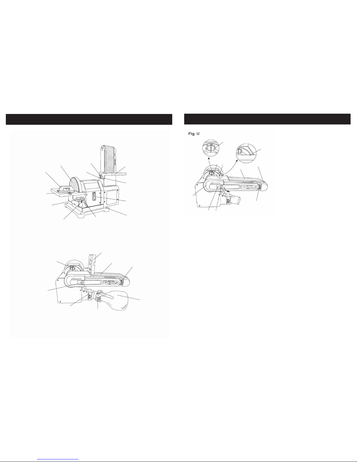
10
Belt worktable
Worktable scale
Worktable knob
Angle pointer
Sanding disc
Mitre guage
Disc worktable
Worktable scale
Angle pointer
Worktable handle
Bench mounting hole
NVR switch
Dust bag
Dust bag clamp
Belt worktable
Sanding belt
Tracking knob
Belt vertical screw
Belt tension lever
Dust extraction port
GETTING TO KNOW YOUR BELT / DISC SANDER
19
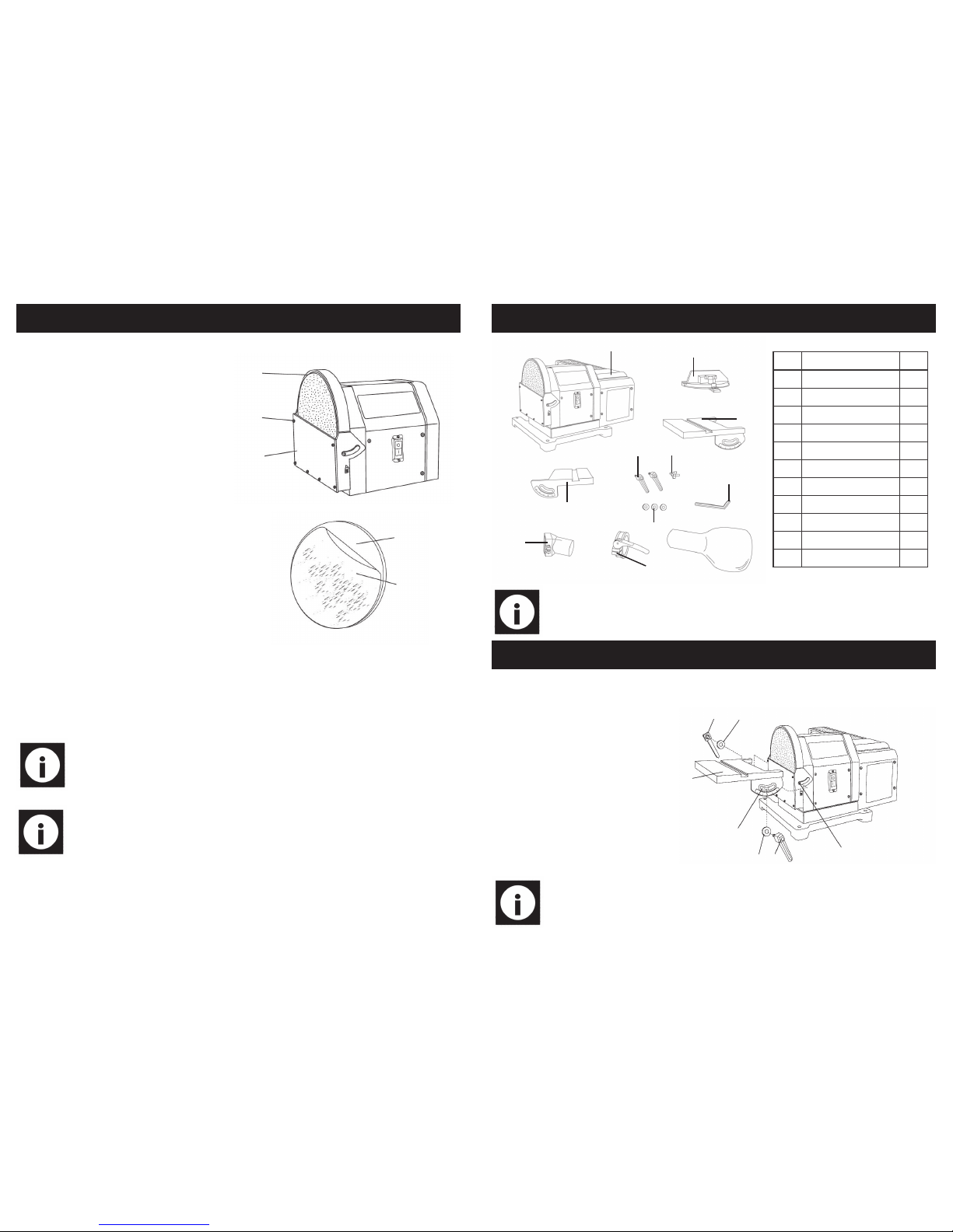
1.Remove the belt worktable.
2.Position the belt work support frame horizontally as shown in Fig. U; Loosen the inner
hex screw (1) using a 5 mm hex wrench, turning it anti-clockwise. Do not remove
the screw.
3.Remove the two screws (2, 3) using a screwdriver, and pull out the tension lever (4)
to release the tension of the sanding belt (5). Remove the belt exhaust cover (6).
4.Remove the sanding belt (5) from both sanding drums (7).
5.Place new sanding belt over the sanding drums. Make sure the belt arrow located
on the inside of the belt is pointed in the right direction.
6.Replace the belt exhaust cover (6) into position. Replace and tighten the two
screws (2, 3) and push the tension lever (4) in to apply belt tension.
7.Track the belt by following the instructions on page 15.
8.Plug in the sander and turn the switch ON and OFF quickly to check if the sanding
belt moves to either side. Re-adjust and fine-tune the tracking knob if necessary.
CARE AND MAINTENANCE….cont
1
1
2
2
3
4
8
6
5
7
Page 11
18
1
2
3
1.Remove the disc worktable, and
then remove the disc cover (1) by
removing six screws (2).
2.Remove the existing disc, and
clean any residue left on disc plate
(3). Only use mineral spirits to remove this residue.
3.Peel the plastic (4) back from new
sanding disc (5) and carefully press
sanding disc firmly in position around
the sanding plate. Make sure the
disc is centered on the plate.
4.Reinstall the disc cover, tighten
screws and place sanding table
back on unit.
4
5
Replacing the sanding belt.
Note: For your safety, turn switch OFF and remove the mains lead from the
electrical outlet before adjusting or performing maintenance on your
sander.
Note: Use only sanding belts that measures 4 in. (102 mm) in width / 36 in.
(914 mm) in length.
CARE AND MAINTENANCE….cont
11
A
B
C
D
E
F
K
G
H
I
J
1
2
3
4
2
5
1
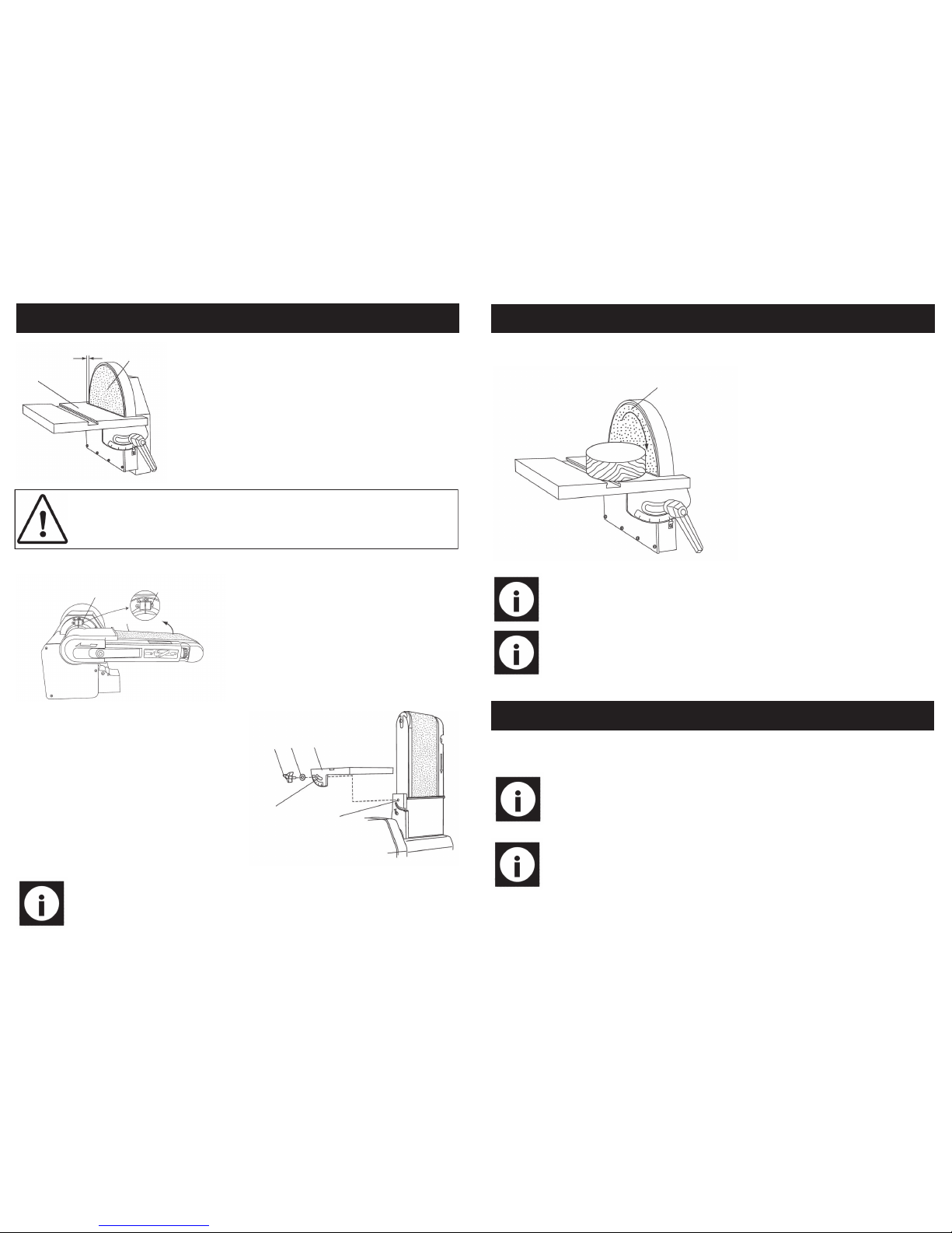
1.Locate the worktable lock handles (1) and washers (2).
2.Place the worktable (3) onto
the sander, aligning the semicircle slot (4) and the threaded
hole (5).
3.Put a washer (2) on the worktable lock handle (1), insert
through the semi-circular slot
(4), and then tighten into
threaded hole (5), repeat on
the other side of the table.
Note: Always check to make sure both handles are tight before beginning
any sanding operations.
Attaching the disc worktable.
ASSEMBLY INSTRUCTIONS
Ref. Descr iption QTY
A Belt / disc sander 1
B Mitre guide 1
C Disc worktable 1
D Hex key 1
E Dust bag 1
F Washers 3
G Knob 1
H Lock handle 2
I Belt worktable 1
J Dust extractio n port 1
K Dust bag clamp 1
Note: If any of the above items are missing, contact your distributor imme-
diately.
CONTENTS AND ACCESSORIES
Page 12
12
Fig.1
2
1
1.6mm
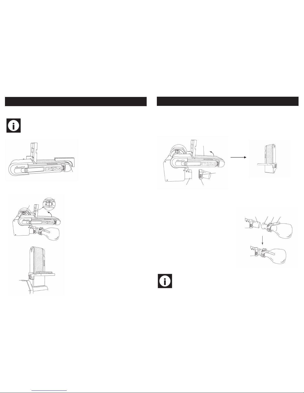
Attaching the belt worktable.
Note: The belt worktable should be used to support work-pieces in all sand-
ing operations except for inside curve applications.
1
1
2
1.Loosen the belt angle locking screw (1)
using a 5mm hex key, raise the belt bed
(2) into a vertical position, then re-tighten
the screw.
3 4
5
6
7
2.Locate the worktable knob (3) and washer
(4).
3.Place the worktable (5) onto the sander
frame, aligning the semi-circle slot (6) with
the threaded hole (7).
4.Place a washer (4) onto the threaded
shaft of the worktable knob (3).
5.Insert through semi-circular slot (6) and
tighten into threaded hole (7).
Caution: To avoid trapping the work piece or fingers between the worktable (1) and the sanding disc (2), leave a maximum gap of 1.6mm as
shown in fig.1
ASSEMBLEY INSTRUCTIONS….cont
17
Sanding outside curves.
1
Note: Always sand on the right (downward) side of the sanding disc (1) as
shown. Sanding on the left (upward) side of the sanding disc could
cause the work piece to jump or kickback.
Note: The edge of the table must be positioned a maximum of 1.6 mm
from the sanding disc to avoid trapping the work piece or fingers between
the disc table and sanding disc.
Freeha nd sanding of outside
curves should be done on the
sanding disc (1). Keep fingers a
minimum of 1 in. (25.4 mm) from
the sanding disc.
CARE AND MAINTENANCE
Note: To avoid injury, turn switch OFF and disconnect the plug from the
power source before removing and installing sanding belt.
Replacing the sanding disc.
Note: A sanding disc is pre-mounted at the factory. Use only sanding discs
that measures 8 in. (203 mm) in diameter.
OPERATING INSTRUCTIONS….cont
Page 13
16
Sanding inside curves.
Note: To avoid injury, do not apply the end of the work piece to the idler
drum (1). This could cause the work piece to fly up or cause kickback.
1
With care, freehand sanding of inside
curves can be accomplished on the
idler drum (1). Never attempt to sand
the ends of a work piece on the idler
drum (1).
Belt vertical sanding.
1
1
The belt / disc sander can sand vertically as well
as horizontally. Depending on operator needs
and the work piece, the worktable can be used
with either the horizontal or vertical position.
1.Locate the 5 mm hex key.
2.Loosen the inner hex screw (1) by turning it anti
-clockwise.
3.Manually move the sanding bed into the vertical or horizontal position, as required.
4.Re-tighten the inner hex screw (1) by turning it
clockwise.
OPERATING INSTRUCTIONS….cont
13
Attaching the extraction port.
1
2
3
4
1.Ensure that the belt bed (1) is in the vertical position (as shown on page12).
2.Loosen the hex screw (2) using a 5mm hex screw, attach the dust extraction port (3)
onto the dust port (4), and re-tighten the hex screw (2).
Note: It is extremely important that the dust bag is connected to the machine before any sanding operations are carried out, we also recommend
using a mask or respirator even when the dust bag is connected,
3
4
5
6
3.Insert the opening of the dust bag (4) into
bag clamp (5).
4.Attach the dust bag (4) onto the dust port
(3).
5.Tighten the bag clamp handle (7) clockwise
one or two full turns before locking, do not
over tighten.
Attaching the dust bag.
ASSEMBLEY INSTRUCTIONS….cont
Page 14
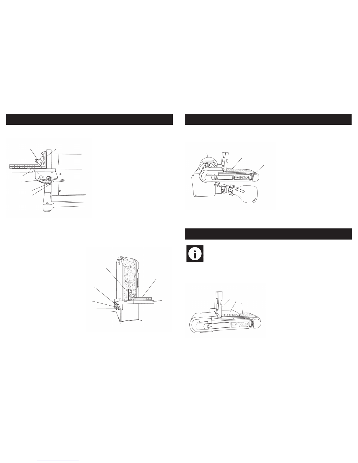
14
1
2
3
4
5
6
1.Using a combination square (1),
place one side of the square on the
disc worktable (2) with the other side
against the sanding disc (3) to check
to see if the disc worktable is at 90°.
2.If its not at 90°, loosen the lock han-
dles (4).
3.Adjust the table square with the disc
and re-tighten the lock handles (4).
4.Loosen the screw (5) and set the
scale pointer (6) to 0°.
Adjusting the table square with the disc.
Adjusting the table square with the belt.
1.Agai n, using the combin ati on
square (1), place one side of the
square on to the belt worktable (2),
place the other side against the
sanding belt (3) and check to see if
its at 90°.
2.If its not at 90°, loosen the table lock
knob (4), adjust the table square to
the belt and re-tighten the lock
knob.
3.Loosen the screw (5) and set the
scale pointer (6) to 0°.
1
2
3
4
5
6
ADJUSTMENTS
15
Note: This belt disc sander is designed only for sanding operations involving
wood or wood derived products. It is not suitable for use with any type of
metal - your warranty will be void if the sander is used for this purpose.
Tracking the belt.
1
2
3
1.Turn the sanding belt slowly by
hand, noting if the belt (1) tends to
slide off the bed, and to which side
front or back.
2.If it doesn't slide from side to side
then the belt is tracked correctly.
3.Viewed from the switch end, if the
sanding runs towards the disc (2),
slightly turn the tracking knob (3)
clockwise.
4.Viewed from the switch end, if the
sanding belt runs away from the
disc, slightly turn the tracking knob
(3) anti-clockwise.
5.Readjust tracking knob another 1/4
turn, as necessary.
OPERATING INSTRUCTIONS
Belt horizontal sanding.
1
2
3
When using the sanding belt in the horizontal position, to perform surface or edge
sanding, the belt worktable (1) must always
be used. Always hold the work piece (2)
firmly, keeping your fingers away from the
sanding belt . Always keep the end of the
work piece against the belt worktable (1)
and move the work evenly across the
sanding belt. Apply only enough pressure
to allow the sanding belt to remove material. Use extra caution when sanding very
thin pieces.
ADJUSTMENTS….cont
 Loading...