

Page 1
Please dispose of packaging for the product in a responsible
manner. It is suitable for recycling. Help to protect the
environment, take the packaging to the local amenity tip
and place into the appropriate recycling bin.
Never dispose of electrical equipment or batteries in with
your domestic waste. If your supplier offers a disposal facility please use it or alternatively use a recognised re-cycling
agent. This will allow the recycling of raw materials and help
protect the environment.
01940
14”x 43” Wood
Lathe
FOR HELP OR ADVISE ON THIS PRODUCT PLEASE CONTACT YOUR DISTRIBUTOR.
Ref:180311
20
Please read and fully understand the instructions in
this manual before operation. Keep this manual
safe for future reference
1
Page 2

NOTES
2
19
Page 3

PARTS LIST….cont
61. Rotating Centre 70. Leg Stand-1
62. Tailstock Spindle 71. Leg Stand-2
CONTENTS
63. Tailstock Screw 72. Switch
64. Handle Assembly 73. Switch Box
65. Tailstock 74. Mains Lead
66. Washer 75. Instruction Manual
67. Hand-wheel 76. Capacitor
68. Screw (M8 x 20) 77. Digital Readout
69. Cap Head Bolt (M8 x 35) 78. Screw
Page No. Description
3 Contents
4 General Safety Instructions
6 Specific Safety Instructions
8 Technical Specifications
8 Contents and Accessories
9 Electrical Connection
10 Guarantee
13 Assembly Instructions
12 Operating Instructions
15 Maintenance
16 Exploded Drawing
17 Parts List
19 Notes
18
3
Page 4

GENERAL SAFETY INSTRUCTIONS
PARTS LIST
1. KNOW YOUR POWER TOOL. Read this owner's manual carefully. Learn the tool's applications and limitations, as well as its specific potential hazards.
2. KEEP GUARDS IN PLACE and in working order, never use the tool if any damage is
present.
3. REMOVE ADJUSTING KEYS AND WRENCHES. Form a habit of checking to see that adjusting tools and wrenches are removed from machine before turning it on.
4. KEEP WORK AREA CLEAN. Cluttered areas and benches invite accidents.
5. DON’T USE IN DANGEROUS ENVIRONMENTS. Don't use power tools in damp or wet
locations, or expose them to rain. Keep work area well lit. Don't use the tool in the presence of flammable liquids or gases.
6. KEEP CHILDREN AWAY. All visitors should be kept a safe distance from work area.
7. MAKE THE WORKSHOP CHILD PROOF with padlocks, master switches or by removing
starter keys.
8. DON’T FORCE THE TOOL. It will do the job better and safer at the rate for which it was
designed.
9. USE THE CORRECT TOOL. Don't force the tool or attachment to do a job for which it
was not designed; for example, don't use a circular saw for cutting tree limbs or logs.
10. WEAR PROPER APPAREL. Do not wear loose clothing, gloves, neckties, rings, bracelets, or other jewellery which may get caught in moving parts. Non-slip footwear is recommended. Wear protective hair covering to contain long hair.
11. ALWAYS USE SAFETY GLASSES. Also use a face or dust mask if cutting operation is
dusty everyday, eyeglasses only have impact resistant lenses, they are NOT safety
glasses.
12. SECURE WORK. Use clamps or a vice to hold work when practical. It's safer than
using your hand and it frees both hands to operate tool.
13. DON’T OVERREACH. Keep proper footing and balance at all times.
14. MAINTAIN TOOLS WITH CARE. Keep tools sharp and clean for best and safest per-
formance. Follow instructions for lubricating and changing accessories.
15. DISCONNECT THE TOOL. Before servicing; when changing accessories such as
blades, bits, cutters, and the like.
16. REDUCE THE RISK OF UNINTENTIONAL STARTING. Make sure the switch is in the OFF
position before plugging in or inserting battery if applicable.
17. USE RECOMMENDED ACCESSORIES. Consult the owner's manual for recommended accessories. The use of improper accessories may cause risk of injury to persons or damage to the tool.
18. NEVER STAND ON THE TOOL. Serious injury could occur if the tool is tipped or if the
cutting tool is accidentally contacted.
19. CHECK FOR DAMAGED PARTS. Before every use of the tool, check the guard or
other parts for damage, check to determine that it will operate properly and perform
its intended function - check for alignment of moving parts, binding of moving parts,
its operation. A guard or other part that is damaged should be properly repaired or
replaced.
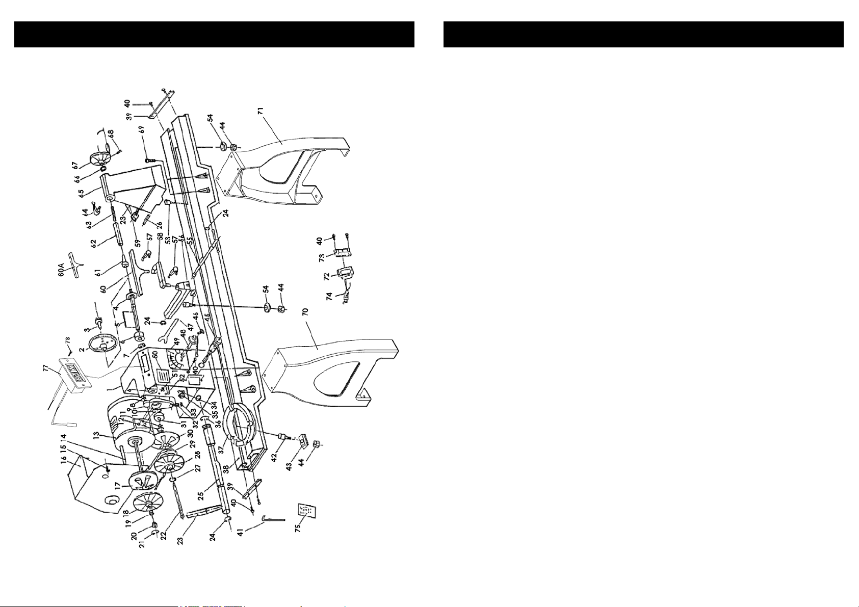
1. Headstock 31. Bearing (80107)
2. Faceplate 32. Bolt (M8 x 20)
3. Drive Spur 33. Nut (M8)
4. Spindle 34. Clamp
5. Key (4 x 4 x 80) 35. Nut
6. Bearing (80205Z) 36. “C” ring (22)
7. “C'' ring (52) 37. Turning Base
8. Spring 38. Main Bed
9. Shifting Lever Bracket 39. Stop Bracket
10. “C” ring (62) 40. Screw (M5 x 10)
11. “C” ring (30) 41. Hex Wrench
12. “C” ring (35) 42. Cam Bolt
13. Motor 43. Clamp-A
14. Key (4 x 4 x 80) 44. Hex Nut (M18)
15. Screw (M5 x 8) 45. Angular Setting Assembly
16. Motor Cover 46. Screw (M5 x 12)
17. Motor Pulley (L) 47. Spindle Wrench
18. Motor Pulley (R) 48. Gear Assembly
19. Spring 49. Speed Label
20. Sleeve 50. Name Label
21. “C” ring (16) 51. Bolt (M8 x 30)
22. Push Rod 52. Rack
23. Headstock Locking Handle 53. Cam Bolt
24. “C” ring (19) 54. Clamp-B
25. Eccentric Rod 55. Eccentric Rod
26. Pin 56. Tool Rest Body
27. “C” ring (24) 57. Handle Assembly
28. Spindle Pulley (L) 58. Tool Rest Extension
29. V-belt 59. Tailstock Locking Handle
30. Spindle Pulley (R) 60. Tool Rest
4
17
Page 5
EXPLODED DRAWING
GENERAL SAFETY INSTRUCTIONS….cont
20. DIRECTION OF FEED. Feed work into a blade or cutter against the direction of rotation of the blade or cutter only.
21. NEVER LEAVE THE TOOL RUNNING UNATTENDED. TURN the power off. Don't leave
the tool until it comes to a complete stop.
22. DON’T ABUSE CORD. Never carry the tool by the cord or pull it to disconnect the
plug from the mains socket. Keep cord away from heat, oil and sharp edges.
23. USE SUITABLE VOLTAGE. Before connecting the machine to a power source, be
sure that the voltage supplied is the same as that specified on the nameplate of the
machine.
16
5
Page 6
SPECIFIC SAFETY INSTRUCTIONS
MAINTENANCE
Caution! If used incorrectly, woodworking machines can be dangerous;
for this reason always comply with the safety instructions mentioned in this
manual.
WARNING: Do not operate your wood lathe until it is completely assembled and installed according to the instructions.
1. For your own safety, read the entire instruction manual before operating the lathe.
2. Always wear eye protection.
3. Do not wear gloves, neckties, or loose clothing.
4. Tighten all locks before operating.
5. Do not mount a split work-piece.
6. Use the lowest speed when starting to cut a new work-piece, If the lathe is running
so fast that it vibrates, there is a risk that the work-piece will be thrown out or the tool
jerked from your hands.
7. Read and understand all warning labels attached to the wood lathe.
8. Stop and start the wood lathe at slow speed.
9. Always rotate the work-piece by hand before turning on the lathe. If the work-piece
strikes the tool rest, it could split and be thrown out of the lathe.
10. Do not allow the turning tools to bite into the wood. The wood could split or
be thrown out from the lathe.
11. Do not operate the lathe if it is rotating in the wrong direction. The work-piece must
always be rotating toward you.
12. Before attaching a work-piece to the faceplate, always rough it out to make it as
round as possible, this minimizes the vibrations while the piece is being turned. Always
fasten the work-piece securely to the faceplate, failure to do so could result in the
work-piece being thrown away from the lathe.
13. Position your hands so that they will not slip onto the work-piece.
14. Remove all loose knots in the stock before mounting it between the centres or on
the faceplate.
15. Leave the work area only after the lathe's motor has some to a full stop.
16. Keep your chisels and turning tools within easy reach while working. Do not lay
them on the bench so that you must reach over the revolving work-piece to select
them.
17. Keep a firm hold and remain in control of the cutting tool at all times. Take special
precautions when shaping a section of stock in which knots or voids are found.
18. Always make safety a priority.
WARNING - FOR YOUR OWN SAFETY; ALWAYS TURN THE LATHE OFF AND DISCONNECT IT
FROM THE MAINS SUPPLY BEFORE
WORK ON THE LATHE.
• Vacuum and / or blow out any dust accumulation inside the motor housing on
a regular basis.
• Apply a coat of paste wax, or similar to the lathe bed to help keep it clean and
to facilitate the easy movement of the articulated tool rest and tailstock.
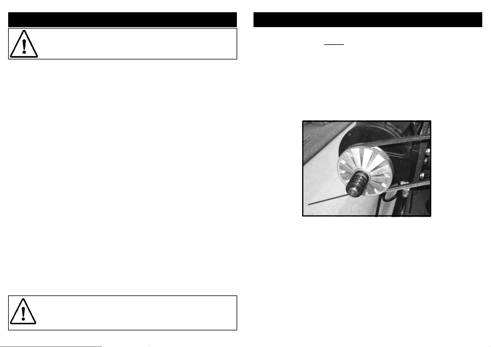
• Proper Oiling and maintenance must take place to ensure the quality and life of
the machine. To Maintain this, the use of a pin point oiler would be helpful. Take
the headstock cover off, and oil the point in the diagram. This should be done
periodically.
Periodic lubrication of the spring levers and other threaded parts will make them easier
to operate and prevent any possible corrosion.
PERFORMING ANY MAINTENANCE OR LUBRICATION
CAUTION: THE WARNINGS AND CAUTIONS MENTIONED IN THIS INSTRUCTION MANUAL
CAN NOT COVER ALL POSSIBLE CONDITIONS AND SITUATIONS THAT MAY OCCUR. IT
MUST BE UNDERSTOOD BY THE OPERATOR THAT COMMON SENSE AND CAUTION ARE
FACTORS WHICH CAN NOT BE BUILT INTO THIS PRODUCT, BUT MUST BE APPLIED.
6
15
Page 7
OPERATING INSTRUCTIONS….cont
SPECIFIC SAFETY INSTRUCTIONS….cont
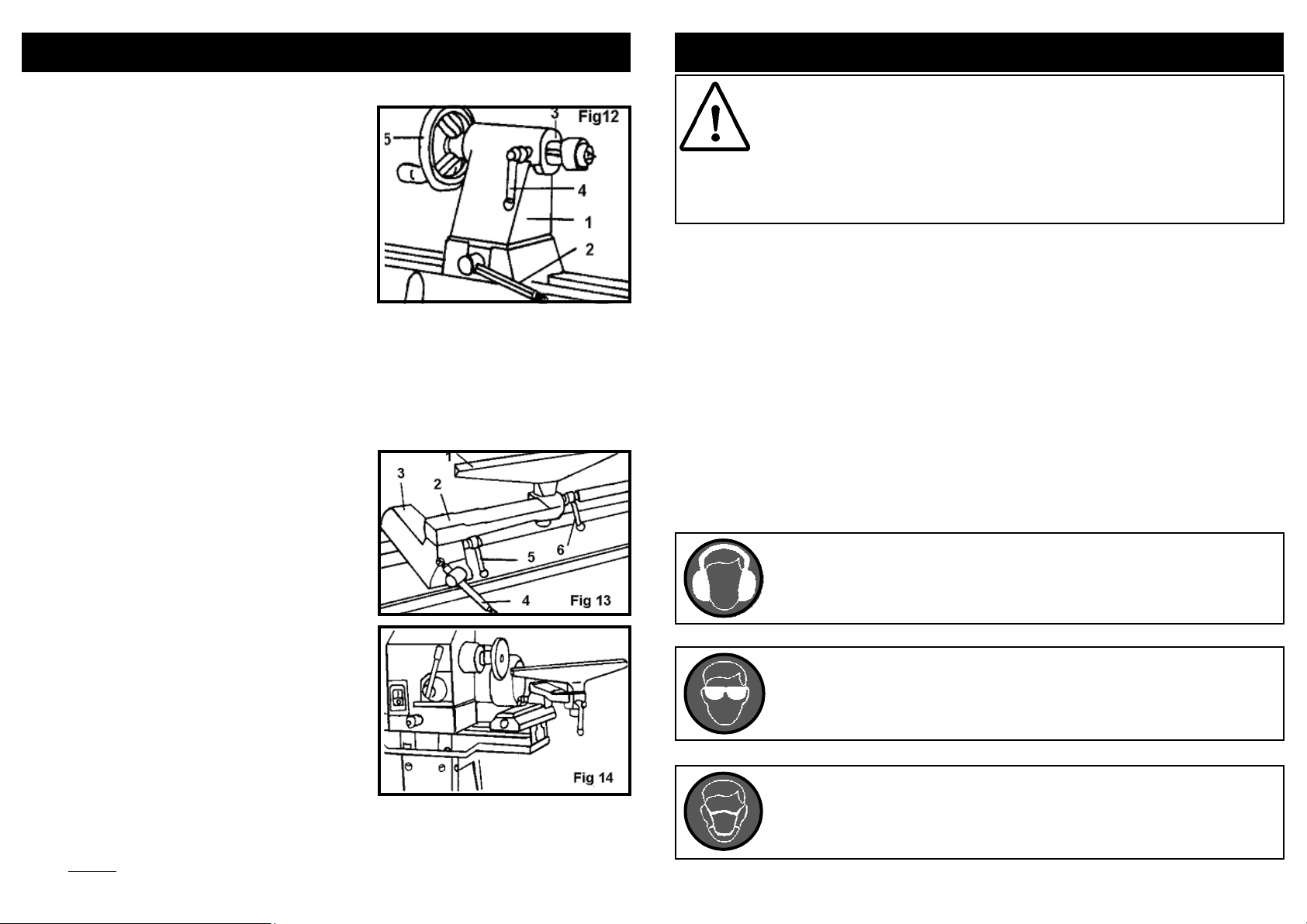
Operating The Tailstock:
• Move the tailstock (1) by loosening the tailstock lock lever (2) and sliding the tailstock
assembly to the desired position on the
lathe bed. Securely lock the tailstock into
position by tightening the lock lever.
• The tailstock spindle (3) can extend up to
2-½" from the tailstock housing. You can
move the tailstock spindle by loosening
the spindle lock lever (4) and then rotating
the spindle hand wheel (5).
• Be sure that lock levers (4) and (2) are secure before operating the lathe.
• The tailstock spindle is hollow and can be
accessed from the hand wheel end. Use
the push rod to remove the Morse Taper
live centre.
Operating The Tool Rest:
The articulated tool rest (1) may be used with or
without the extension arm (2).
To move the tool rest base (3) loosen the lock
lever (4) and slide the tool rest base left or right
along the lathe bed or it may be moved forward
or backwards.
• When using the tool rest extension arm,
loosen lock levers (5) and (6) to make
any necessary adjustments.
• Be certain to tighten all tool rest locking
levers before turning on the lathe.
• The articulated tool rest may also be repositioned onto the extension section of
the main bed by sliding the headstock to
the right, for use on outboard turnings.
IMPORTANT: Make sure that the tool rest is adjusted to be as close to the work-piece
as possible, without touching. Rotate the work-piece by hand to check the clearance before
turning the lathe on.
WARNING! Before connecting the tool to the mains supply be sure that the
voltage supply is the same as that specified on the nameplate of the tool.
A power source with a voltage greater or lower than that specified for the
tool can result in serious injury to the user, as well as damage to the tool. If
in doubt, do not plug the tool into the mains supply. Always turn the machine off and remove the plug from the mains socket before making any
adjustments or maintenance.
• When an extension cable is required, you must ensure that it has the right ampere rating and a large enough cross section for the mini wood lathe. It should
also be checked to make sure that no damage is present and it is in safe electrical condition.
• Ensure that you have removed foreign objects such as nails and screws from
the work-piece before commencing the operation.
• Rags, cloths, cord, string and anything that could get “dragged” into the lathe
should be removed from the work area prior to use.
• Damaged or contaminated work-pieces may cause unwanted hazards.
• Metal parts penetrated into the work-piece can be very dangerous, and should
be removed before operation starts.
• Use safety equipment including safety goggles or shield, ear protection, dust
mask and protective clothing.
• Check to make sure that all fixing screws etc. are tight before operating the
lathe.
When using this wood lathe, always ensure the operator as well as
those in the area wear ear protection; particularly during extended use.
When using this wood lathe always ensure the operator as well as those
in the area wear eye protection.
Some wood and wood composites / additives have the potential to be
highly toxic; always wear a face mask when operating this wood lathe.
14
7
Page 8
TECHNICAL SPECIFICATIONS
Part Number 01940
Input Voltage 230v ~ 50hz
Power 750 watts
Speed 500 rpm - 2200 rpm (variable)
Distance Between Centres 1100 mm
Maximum Turning Ø 350 mm
Spindle Thread Size 3/4” x 16tpi
Drive Spur Size 1 Morse Taper
Tailstock Rotating Centre Size 2 Morse Taper
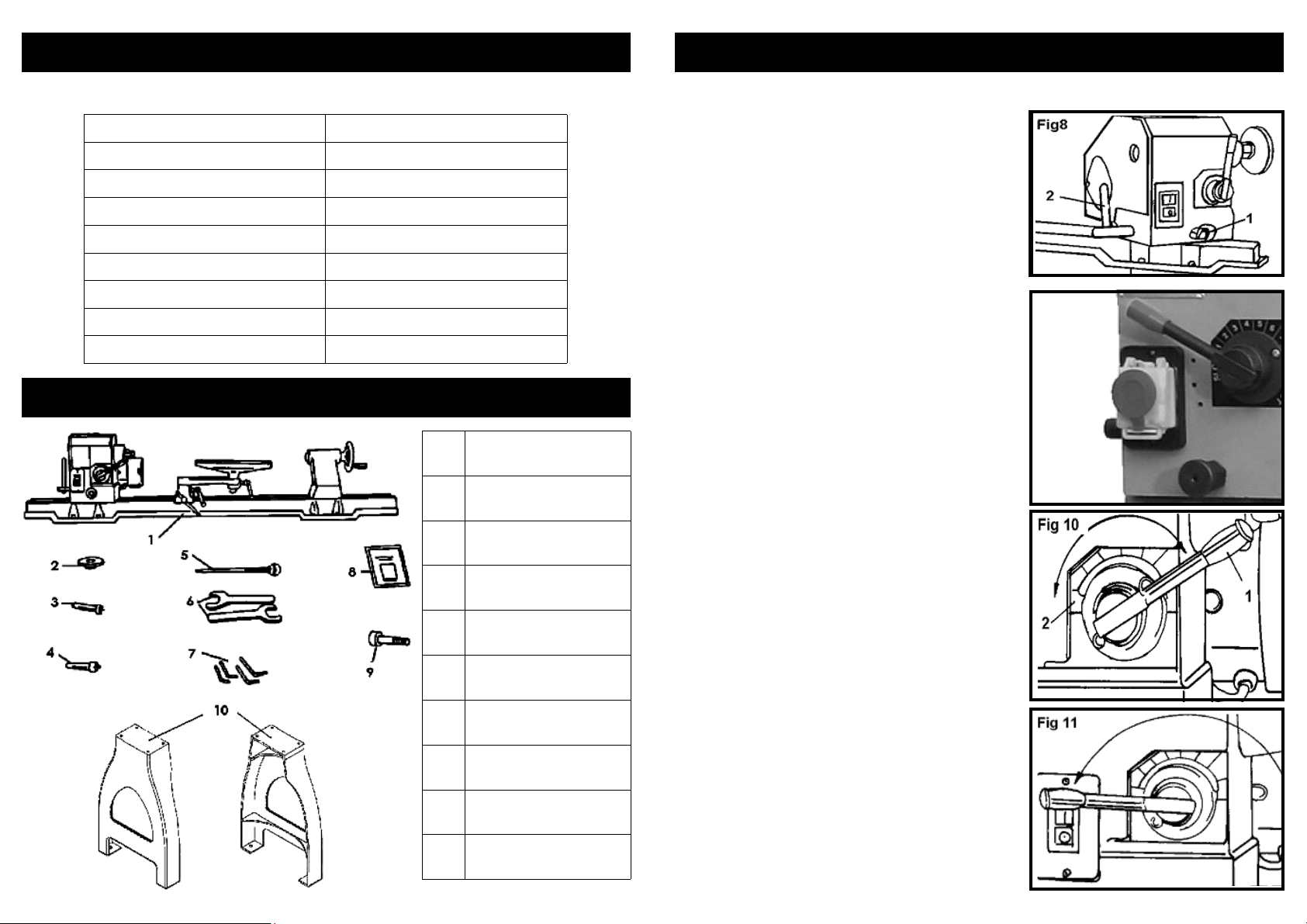
CONTENTS AND ACCESSORIES
1. Lathe Assembly
2. Faceplate
3. Drive Spur
4. Rotating Centre
5. Push Rod
6. Wrenches
7. Hex Keys
8. Instruction Manual
9. Cap Head Bolts
10. Leg Set
OPERATING INSTRUCTIONS….cont
2. To set the headstock at the desired position,
you must first turn the head lock handle [2] until
you have completed at least one rotation. (Fig
8).
3. Pull out the headstock release [1], rotate the
entire headstock clockwise to the desired position. The headstock will be fixed in position when
it locks into one of the five pre-set settings.
Tighten the lock handle [2].
On / Off NVR Switch:
To start the lathe; lift the yellow cover and press
the green button (I).
To stop the lathe; press the red (0) button, or alternatively close the yellow cover.
Your variable speed SIP wood lathe is fitted with
a safety NVR (No Volt Release) switch. This means
that if power is cut to the lathe (such as in a
power failure); the motor will not start to run once
the power is returned without the operator following the above instructions to restart the lathe.
Speed Control:
The lathe motor must be running before you
can use the speed control lever.
The speed control lever can be rotated to any
one of ten fixed speeds; To set the speed:
Pull back on the speed control lever (1) and rotate the lever to the desired speed. Use the index plate (2) as a reference to select the desired
speed.
Rotating the lever clockwise will increase the
speed while a counter clockwise rotation decreases the speed.
Always return the speed control lever to the lowest speed position before turning the lathe off.
Not complying may prevent the motor from
starting and / or cause damage to the lathe.
8
13
Page 9
ASSEMBLY INSTRUCTIONS….cont
ELECTRICAL CONNECTION
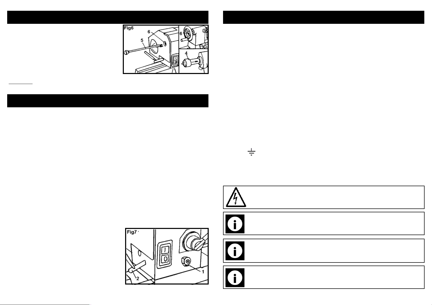
4. To remove either the headstock spur or the
tailstock rotating centre; insert the push rod [5]
into the hole [6] at the opposite end of the
headstock or tailstock and lightly tap. Remove and store the rod in a safe location after use.
WARNING! Do not operate your wood lathe until it is completely assembled and adjusted according to the instructions.
OPERATING INSTRUCTIONS
Operating tips:
1. Make sure cutting tools are sharp and clean for best performance and safe operation.
2. Never leave the work area until the lathe has been turned off and the spindle has
come to a complete stop.
3. Once a work-piece has been clamped onto the lathe, always rotate the workpiece by hand and check for proper tool rest clearance before turning the lathe on.
4. When turning a work-piece, always rough the wood to round form at a low speed to
reduce the risk of kickback.
5. Always position the tool rest firmly and securely just above the centreline of the workpiece when shaping a piece of stock.
6. Remove all loose knots from the stock before it is mounted on to the lathe.
7. Always keep a firm hold on and maintain control of the cutting tool.
8. If you are uncertain about the optimal speed, it is better to start with the slowest,
and increase your speed as your comfort with the tool and the work piece increases.
9. Never force the tool or attachment to do the work of a larger industrial tool. It is designed to do the job better and more safely at the rate for which it was intended.
Headstock (Fig 7):
1. The headstock has 5 preset positions, 0
ting for all spindle turning applications,
0
60
/900/1200 for use when making face plate
turnings, 180
when using the extension section of the main
bed and tool rest extension.
0
for use for face plate turnings
0
set-
Connecting to the power supply:
This SIP wood lathe is fitted with a standard 230v ~ 13 amp plug. Before using the
lathe, inspect the mains lead and plug to ensure that neither are damaged. If any
damage is visible have the lathe inspected / repaired by a suitably qualified person.
If it is necessary to replace the plug a heavy duty impact resistant plug would be preferable.
The wires for the plug are coloured in the following way:
Yellow / green Earth
Blue Neutral
Brown Live
As the colours of the wires may not correspond with the markings in your plug, proceed as follows: The wire which is coloured blue, must be connected to the terminal
marked with N or coloured black. The wire which is coloured brown, must be connected to the terminal, which is marked L or coloured red. The wire which is coloured
yellow / green should be connected to the terminal which is coloured the same or
marked
Always secure the wires in the plug terminal carefully and tightly. Secure the cable in
the cord grip carefully.
Warning: Never connect live or neutral wires to the earth terminal of the
plug. Only fit an approved plug with the correct rated fuse. If in doubt
consult a qualified electrician.
Note: Always make sure the mains supply is of the correct voltage and
the correct fuse protection is used. In the event of replacing the fuse always replace like for like.
Note: If an extension lead is required in order to reach the mains supply;
ensure that this too is rated for the correct voltage and fuse rating (230v ~
13 amps).
Note: The cross section of the extension lead should be checked so that it
is of sufficient size so as to reduce the chances of voltage drops.
12
9
Page 10
GUARANTEE
ASSEMBLY INSTRUCTIONS
Guarantee:
This SIP wood lathe is covered by a 24 month parts and labour warranty covering failure due to manufacturers defects. This does not cover failure due to misuse or operating the machine outside the scope of this manual.
In the unlikely event of warranty claims, contact your distributor as soon as possible.
Proof of purchase will be required before any warranty can be honoured.
Note: Proof of purchase will be required before any warranty can be honoured.
CAUTION: The lathe is a heavy machine and must be lifted with assistance to assemble the lathe to the leg set.
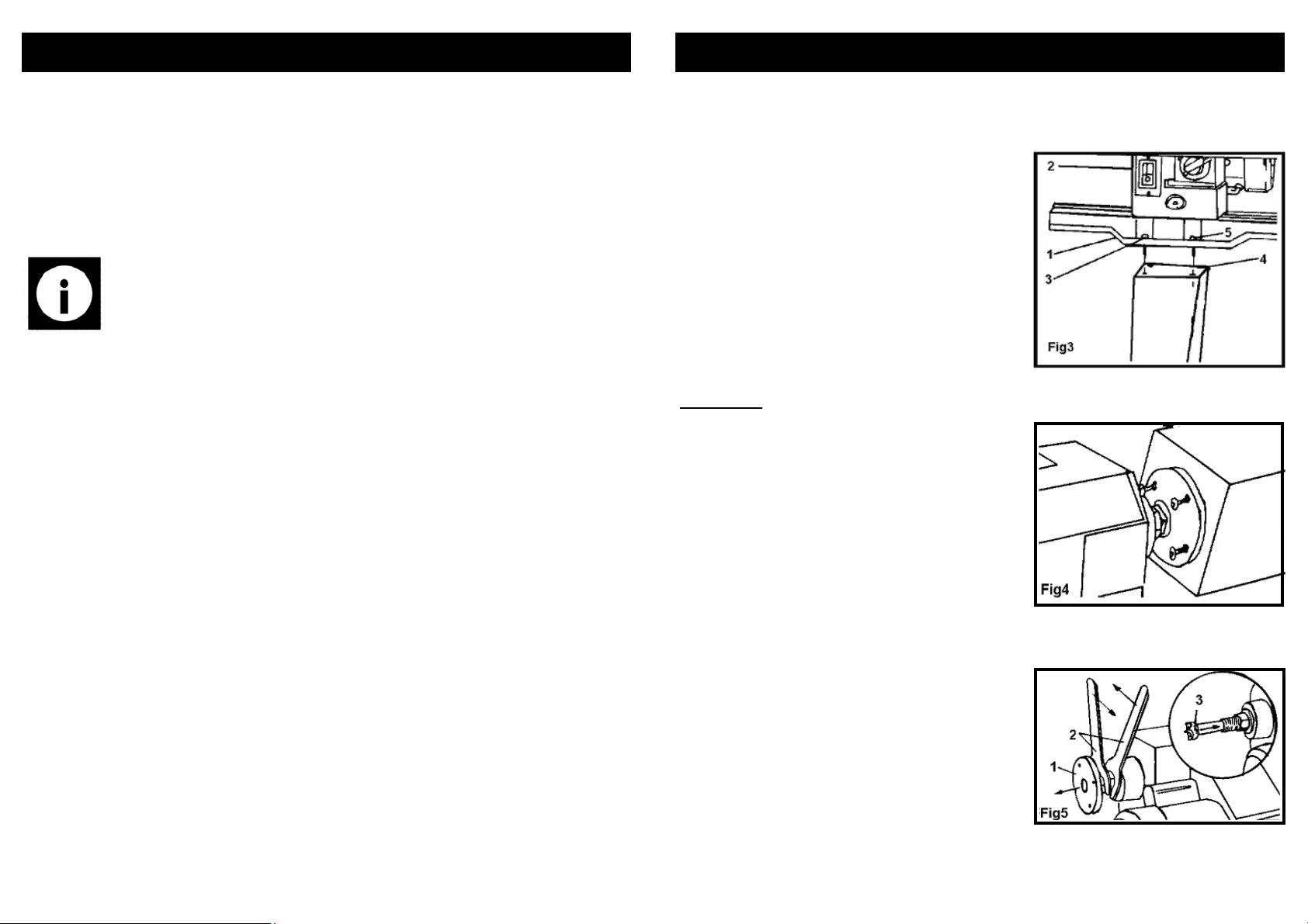
Setting the lathe on the leg set (Fig 3)
1. Place the lathe bed assembly [1] onto the
leg set.
2. Position the headstock [2] assembly over
the top plate and align the holes in the bed
[3] with the holes in the top plate [4]. Set the
head stock down carefully.
3. Align the tailstock assembly end of the
lathe over the top plate mounting holes and
set it down carefully.
4. Insert the hex bolts [5] into the mounting
holes in each bed and tighten securely.
IMPORTANT! THE LEG SET MUST BE FASTENED TO THE SUPPORTING SURFACE.
Faceplate (Fig 4)
1. Remove the headstock spur from the spindle (If fitted).
2. Thread the faceplate onto the Spindle.
3. Mount the work-piece to the faceplate with
flat head brass wood screws. Make sure the
length of the screws does not interfere with
the cutting tools.
Spur / Rotating Centre
1. Remove the faceplate [1] from the headstock spindle, using the two wrenches provided [2] to separate the faceplate from the
spindle nut. (Fig5)
2. Insert the drive spur [3] into the headstock
spindle.
3. Insert the rotating centre [4] in the tailstock
hole. (Fig 6, Page 12)
10
11
 Loading...