

Page 1
32
Ref: 270214
FOR HELP OR ADVISE ON THIS PRODUCT PLEASE CONTACT YOUR DISTRIBUTOR,
OR SIP DIRECTLY ON:
TEL: 01509500400
EMAIL: [email protected] or [email protected]
www.sip-group.com
Please dispose of packaging for the product in a responsible
manner. It is suitable for recycling. Help to protect the
environment, take the packaging to the local amenity tip
and place into the appropriate recycling bin.
Never dispose of electrical equipment or batteries in with
your domestic waste. If your supplier offers a disposal facility please use it or alternatively use a recognised re-cycling
agent. This will allow the recycling of raw materials and help
protect the environment.
1
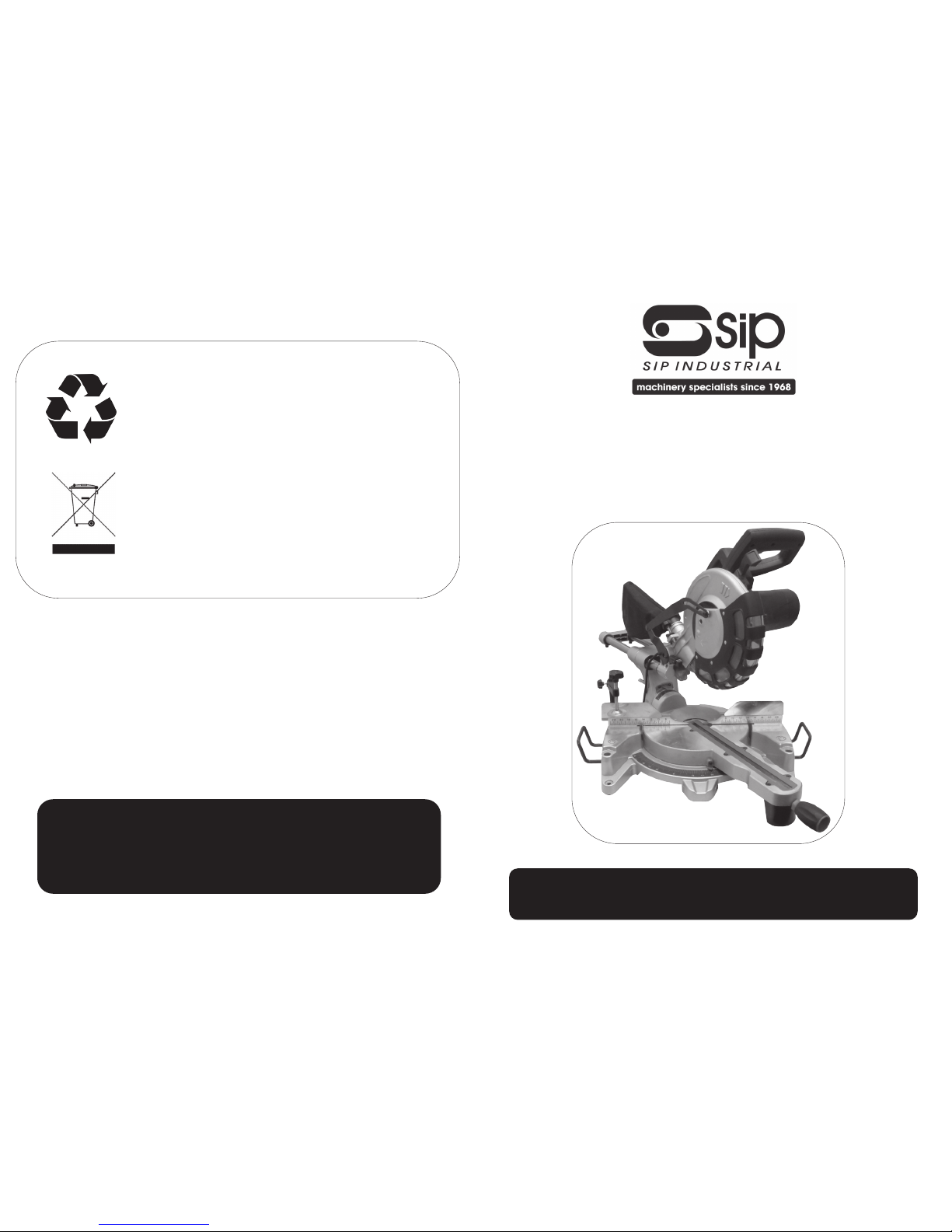
10” Compound Sliding Mitre
Saw
With Laser
01511
Please read and fully understand the instructions in this manual
before operation. Keep this manual safe for future reference.
Page 2

2
31
Declaration of Conformity
We
SIP (Industrial Products) Ltd
Gelders Hall Road
Shepshed
Loughborough
Leicestershire
LE12 9NH
England
As the manufacturer's authorised representative within the EC
declare that the
10” Compound Sliding Mitre Saw - SIP Pt. No. 01511
Conforms to the requirements of the following directive(s), as indicated.
2006/95/EC Low Voltage Directive
2006/42/EC Machinery Directive
2004/108/EC EMC Directive
2002/95/EC ROHS Directive
As Amended By
2008/35/EC
And the relevant harmonised standard(s), including,
EN 55014-1+A1:2009
EN 55014-2+A2:2008
EN 61000-3-2+A2:2009
EN 61000-3-11:2000
Signed:
Mr P. Ippaso - Managing Director - SIP (Industrial Products) Ltd
Date: 31/05/2013.
DECLARATION OF CONFORMITY
Page 3
30
NOTES
3
CONTENTS
Page No. Description
4. Safety Symbols Used Throughout This Manual
4. Safety Instructions
8. Technical Specifications
9. Electrical Connection
10. Guarantee
10. Contents and Accessories
11. Getting To Know Your Saw
13. Assembly Instructions
14. Operating Instructions
19. Maintenance
25. Exploded Drawing
27. Parts List
31. Declaration of Conformity
Page 4
4
When using electric tools, basic safety precautions should always be followed to reduce the risk of fire, electric shock and personal injury.
Read all these instructions before operating the tool and save this user manual for future reference.
SIP recommends that this tool should not be modified or used for any application other than that for which it was designed. If you are unsure of its relative applications do
not hesitate to contact us and we will be more than happy to advise you.
KNOW YOUR POWER TOOL: Read and understand the owner's manual and labels affixed to the tool. Learn its applications and limitations, as well as the potential hazards
specific to this tool.
KEEP WORK AREA CLEAN AND WELL LIT: Cluttered work benches and dark areas invite
accidents. Floors must not be slippery due to oil, water or sawdust etc.
DO NOT USE THE TOOL IN DANGEROUS ENVIRONMENTS: Do not use power tools in
damp or wet locations, or expose them to rain. Provide adequate space surrounding
the work area. Do not use in environments with a potentially explosive atmosphere.
KEEP CHILDREN AND UNTRAINED PERSONNEL AWAY FROM THE WORK AREA: All visitors
should be kept at a safe distance from the work area.
STORE TOOLS SAFELY WHEN THEY ARE NOT IN USE: All tools should be stored in a dry,
locked cupboard wherever possible and out of the reach of children.
WEAR THE CORRECT CLOTHING: Do not wear loose clothing, neckties, rings, bracelets,
or other jewellery, which may get caught in moving parts. Non-slip footwear is recommended. Wear protective hair covering to contain long hair. Roll long sleeves up
Danger / Caution: Indicates risk of personal injury and/or the possibility of
damage.
SAFETY SYMBOLS USED THROUGHOUT THIS MANUAL
Warning: Risk of electrical injury or damage!
Note: Supplementary information.
SAFETY INSTRUCTIONS
IMPORTANT: Please read the following instructions carefully, failure to do
so could lead to serious personal injury and / or damage to the mitre
saw.
29
Ref. No. Description SIP Part No. Ref. No. Description SIP Part No.
133. Nylon hex. nut WD01-00619 159. Steel ball WD01-00644
134. Washer WD01-00620 160. Spring WD01-00645
135. Cap head bolt WD01-00621 161. Screw WD01-00646
136. Screw WD01-00622 162. Table bolt WD01-00647
137. Angle guide plate WD01-00623 163. Screw WD01-00648
138. Screw WD01-00624 164. Support wing WD01-00649
139. Table insert WD01-00625 165. Fence WD01-00650
140. Screw WD01-00626 166. Screw WD01-00651
141. Table WD01-00627 167. Fence extension WD01-00652
142. Mitre indicator WD01-00628 168. Screw WD01-00653
143. Screw WD01-00629 169. Clamp disc WD01-00654
144. Bushing WD01-00630 170. Clamp arm WD01-00655
145. Bushing cover WD01-00631 170-1.
Complete clamp assembly
WD01-00656
146. Screw WD01-00632 171. Clamp knob WD01-00657
147. Knob for extension arm WD01-00633 172. Clamp knob WD01-00658
148. Table front support WD01-00634 173. Clamp shaft WD01-00659
149. Locking shoe WD01-00635 174. Cap head bolt WD01-00660
150. Spring pin WD01-00636 175. Knob WD01-00661
151. Table locking bolt WD01-00637 176. Knob WD01-00662
152. Extension arm WD01-00638 177. Fence extension rig ht WD01-00663
153. Lock handle WD01-00639 178. Cap head bolt WD01-00664
154. Screw WD01-00640 179. Washer WD01-00665
155. Lock handle cap WD01-00641 181. Washer WD01-00666
156. Base WD01-00642 182. Washer WD01-00667
157. Rubber foot WD01-00643 183 Dust bag WD01-00668
PARTS LIST….cont
Page 5

28
Ref. No. Description SIP Part No. Ref. No. Description SIP Part No.
61. Screw WD01-00560 96. Spring pin WD01-00589
62. Inner blade flange WD01-00561 97. Locking pin spring WD01-00590
63. Blade Various 98. Locking pin knob WD01-00591
64. Outer blade flange WD01-00562 99. Screw WD01-00592
65. Blade bolt WD01-00563 100. Spring washer WD01-00593
67. Special screw WD01-00564 101 . Countersunk screw WD01-00594
69. Guard spring WD01-00565 102. Bearing cover WD01-00595
70. Screw WD01-00566 103. Screw WD01-00596
72. Guard plate WD01-00567 104. Guide bar end cap WD01-00597
73. Small retaining plate WD01-00568 105. Spring washer WD01-00598
74. Large retaining plate WD01-00569 106. Screw WD01-00599
75. Nut WD01-00570 107. Guide bar WD01-00600
76. Screw WD01-00571 108. Rubber ring WD01-00601
77. Lower blade guard WD01-00572 109. Linear bearing WD01-00602
77-1.
Blade guard assembly
WD01-00573 110. Bushing WD01-00603
79. Screw WD01-00574 111. Nylon hex. nut WD01-00604
80. Linkage assembly WD01-00575 112. Washer WD01-00605
83. Cap head bolt WD01-00576 113. Cap head bolt WD01-00606
84. Torsion spring WD01-00577 114. Knob WD01-00607
85. Spring bushing WD01-00578 115. Bevel lock handle WD01-00608
86. Depth stop plate WD01-00579 116. Washer WD01-00609
87. Spring piece WD01-00580 117. Nut WD01-00610
88. Wave washer WD01-00581 118. Cap head bolt WD01-00611
89. Screw WD01-00582 119. Saw arm WD01-00612
90. Retaining ring wire WD01-00583 121. Short stud WD01-00613
91. Pivot shaft WD01-00584 122. Long stud WD01-00614
92. Pivot bracket WD01-00585 123. Bevel pointer WD01-00615
93. Screw WD01-00586 124. Screw WD01-00616
94. Bearing cover WD01-00587 126. Screw WD01-00617
95. Locking pin WD01-00588 129-1. Laser assembly WD01-00618
PARTS LIST….cont
5
above the elbow.
USE SAFETY GOGGLES AND EAR PROTECTION: Wear CE approved safety goggles at all
times, Normal spectacles only have impact resistant lenses, they are NOT safety glasses. A face or dust mask should be worn if the operation is dusty and ear protectors
(plugs or muffs) should be worn, particularly during extended periods of operation.
PROTECT YOURSELF FROM ELECTRIC SHOCK: When working with power tools, avoid
contact with any earthed items (e.g. pipes, radiators, hobs and refrigerators, etc.). It is
advisable wherever possible to use an RCD (residual current device) at the mains
socket.
STAY ALERT: Always watch what you are doing and use common sense. Do not operate a power tool when you are tired or under the influence of alcohol or drugs.
DISCONNECT THE TOOL FROM THE MAINS SUPPLY: When not in use, before servicing
and when changing accessories such as blades etc.
AVOID UNINTENTIONAL STARTING: Make sure the switch is in the OFF position before
connecting the tool to the mains supply.
NEVER LEAVE THE TOOL RUNNING / CONNECTED WHILST UNATTENDED: Turn off the tool
and disconnect it from the mains supply between jobs. Do not leave machine until it
comes to a complete stop.
DO NOT ABUSE THE MAINS LEAD: Never carry the tool by the mains lead or pull it to remove the plug from the mains socket. Keep the mains lead away from heat, oil and
sharp edges. If the mains lead is damaged, it must be replaced by the manufacturer
or its service agent or a similarly qualified person in order to avoid unwanted hazards.
CHECK FOR DAMAGED PARTS: Before every use of the tool, a guard or other part that is
damaged should be carefully checked to determine that it will operate correctly and
perform its intended function. Check for alignment of moving parts, free running of
moving parts, breakage of parts, and any other conditions that may affect its operation. A guard or other part that is damaged should be correctly repaired or replaced
by an authorised service centre unless otherwise indicated in this instruction manual.
Have defective switches replaced by an authorised service agent. Do not use the tool
if the switch does not turn it on and off.
KEEP ALL GUARDS IN PLACE: And in full working order.
MAINTAIN TOOLS WITH CARE: Keep tools sharp and clean for the best and safest per-
formance. Follow instructions for lubricating and changing accessories. All extension
cables must be checked at regular intervals and replaced if damaged. Always keep
the hand grip on the tool clean, dry and free of oil and grease.
USE ONLY RECOMMENDED ACCESSORIES: Consult this user manual for recommended
accessories. Follow the instructions that accompany the accessories. The use of improper accessories may cause hazards and will invalidate any warranty you may
have.
REMOVE ADJUSTING KEYS AND WRENCHES: Form a habit of checking to see that keys
and adjusting wrenches are removed from the tool before every use.
SECURE THE WORK-PIECE: Use clamps or a vice to hold the work-piece . This frees up
SAFETY INSTRUCTIONS...cont
Page 6
6
Use only the blade flange specified for this tool.
Before each use; Ensure that the blade retaining bolt is fully secure.
Make sure that the table base is properly secured so it will not move during operation.
For your safety; remove the chippings and work debris etc. from the table top
and from inside the extraction port before each operation.
Avoid cutting nails / screws etc.; Remove all obstructions from the work-piece
before cutting.
Make sure that all keys and wrenches are removed before switching on the
saw.
Keep hands out of path of the saw blade, never reach around saw blade.
Make sure the blade is clear of the work-piece before the switch is turned on.
Before making the first cut using the saw, turn the blade by hand to ensure nothing is catching, then turn the saw on and let it run for a while; Watch for vibration
or wobbling that could indicate poor installation or a poorly balanced blade.
Adjust or replace as necessary.
Allow the blade to run up to full speed before cutting.
Stop operation immediately if you notice anything abnormal.
Wait for the saw blade to stop completely and remove from mains supply before servicing or adjusting the saw.
Be alert at all times, especially during repetitive, monotonous operations. Don't
be lulled into a false sense of security. Blades are extremely unforgiving.
Use of improper accessories such as abrasive wheels may cause damage to
the saw and surrounding area as well as increasing the risk of injury.
Turn off the saw and wait for it to complete stop before moving work-piece or
changing settings.
Do not modify the saw to do tasks other than those intended.
Do not perform any operation freehand. The work-piece must be secured firmly
against the base and guide fence with the clamp during all operations; Using
your hand may cause severe injury.
SAFETY INSTRUCTIONS...cont
both hands to operate the tool.
DO NOT OVERREACH: Keep proper footing and balance at all times.
USE THE RIGHT TOOL: Do not use the tool or attachment to do a job for which it was
not designed.
DO NOT FORCE THE TOOL: It will do the job better and more safely at the rate which it
was designed.
DO NOT OPERATE POWER TOOLS IN EXPLOSIVE ATMOSPHERES: Do not use the tool in
the presence of flammable liquids, gases, dust or other combustible sources. Power
tools may create sparks which can ignite the dust or fumes.
DO NOT EXPOSE THE TOOL TO RAIN OR USE IT IN WET CONDITIONS: Water entering a
power tool will greatly increase the risk of electric shock.
27
Ref. No. Description SIP P art No. Ref. No. Description SIP Part No.
1. Cap WD01-00500 31 . Mains leads holder WD01-00530
2. Self tapping screw WD01-00501 32 . Self tapping screw WD01-00531
3. Motor cover WD01-00502 33. Transformer WD01-00532
4. Self tapping screw WD01-00503 34 . Screw WD01-00533
5. Carbon brush (set of 2) WD01-00504 35. Trigger WD01-00534
6. Carbon brush spring WD01-00505 36. Mains lead WD01-00535
7. Brush holder WD01-00506 37. Mains lead protector WD01-00536
8. Screw WD01-00507 38. Screw WD01-00537
9. Spring washer WD01-00508 39 . Carrying handle WD01-00538
10. Washer WD01-00509 40. Carrying handle cover WD01-00539
11. Motor housing WD01-00510 41. Self tappi ng screw WD01-00540
12. Bearing cover WD01-00511 42. Self tapping screw WD01-00541
13. Wave washer WD01-00512 43. Upper handle WD01-00542
14. Bearing WD01-00513 44. Terminal block WD01-00543
15. Armature WD01-00514 45. Trigger switch WD01-00544
16. Field coil WD01-00515 46. Lower handle WD01-00545
17. Self tapping screw WD01-00516 47. Screw WD01-00546
18. Wind g uard WD01-00517 48. Nut WD01-00547
19. Bearing WD01-00518 49. Depth adjust knob WD01-00548
20. Gear casing WD01-00519 50. Special n ut WD01-00549
21. Screw WD01-00520 51 . Upper blade guard WD01-00550
22. Spring washer WD01-00521 52. Needle bearing WD01-00551
23. Washer WD01-00522 53. Retaining ring shaft WD01-00552
24. Anti finger plate WD01-00523 54. Gear WD01-00553
25. Gear lock pin spring WD01-00524 55. Gear bushing WD01-00554
26. Gear lock pin WD01-00525 56. Key WD01-00555
27. Gear lock button WD01-00526 57. Arbor shaft WD01-00556
28. Self tapping screw WD01-00527 58. Bearing WD01-00557
29. Laser switch WD01-00528 59. Screw WD01-00558
30. Laser switch button WD01-00529 60. Gear case cover WD01-00559
PARTS LIST
Page 7
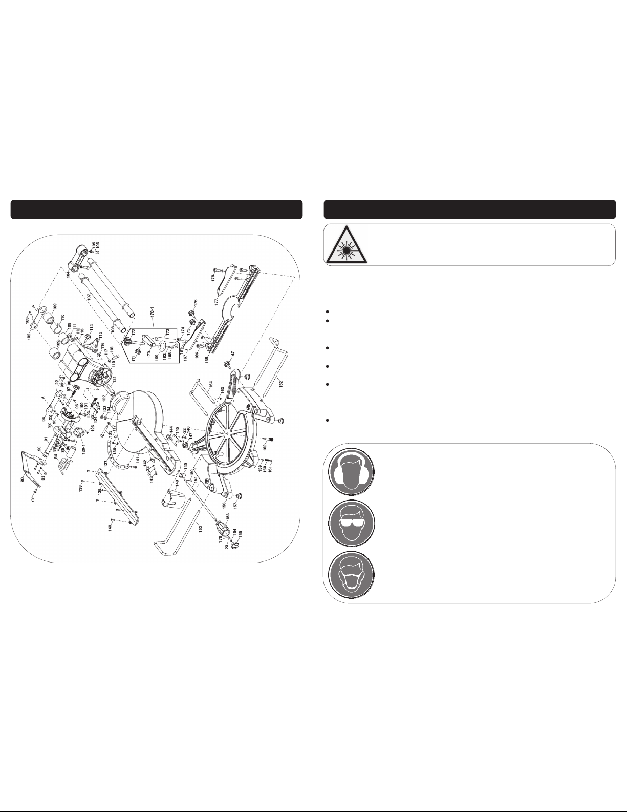
26
EXPLODED DRAWING B
7
This laser complies with class 2 according to EN 60825-1:2007.
The unit includes no servicing components. Do not open the housing for any
reason. If the unit is faulty/damaged, have it repaired/replaced by an authorised repair agent.
Do not stare directly at the laser beam, never aim the beam at any person or
an object other than the work-piece.
Do not deliberately aim the beam at personnel and ensure that it is not directed towards the eye of a person.
Always ensure the laser beam is aimed at a sturdy work-piece without reflective
surfaces. wood or rough coated surfaces are acceptable. Bright shiny reflective
surfaces are not suitable for laser use as the reflective surface could direct the
beam back at the operator.
Always remember to switch off the laser on/off switch (25) after finishing a job,
only turn the laser beam on when the work-piece is on the mitre saw table.
Warning: During use, do not point the laser beam at people, directly or indirectly
through reflecting surfaces.
Some wood and wood composites have the potential to be highly
toxic; always wear a face mask when operating saw.
When using the saw always ensure the operator as well as those in
the area wear ear protection.
When using the saw always ensure the operator as well as those in
the area wear eye protection.
SAFETY INSTRUCTIONS...cont
Warning: The laser beam can potentially cause severe eye damage.
Never look or stare directly into the laser beam.
Page 8
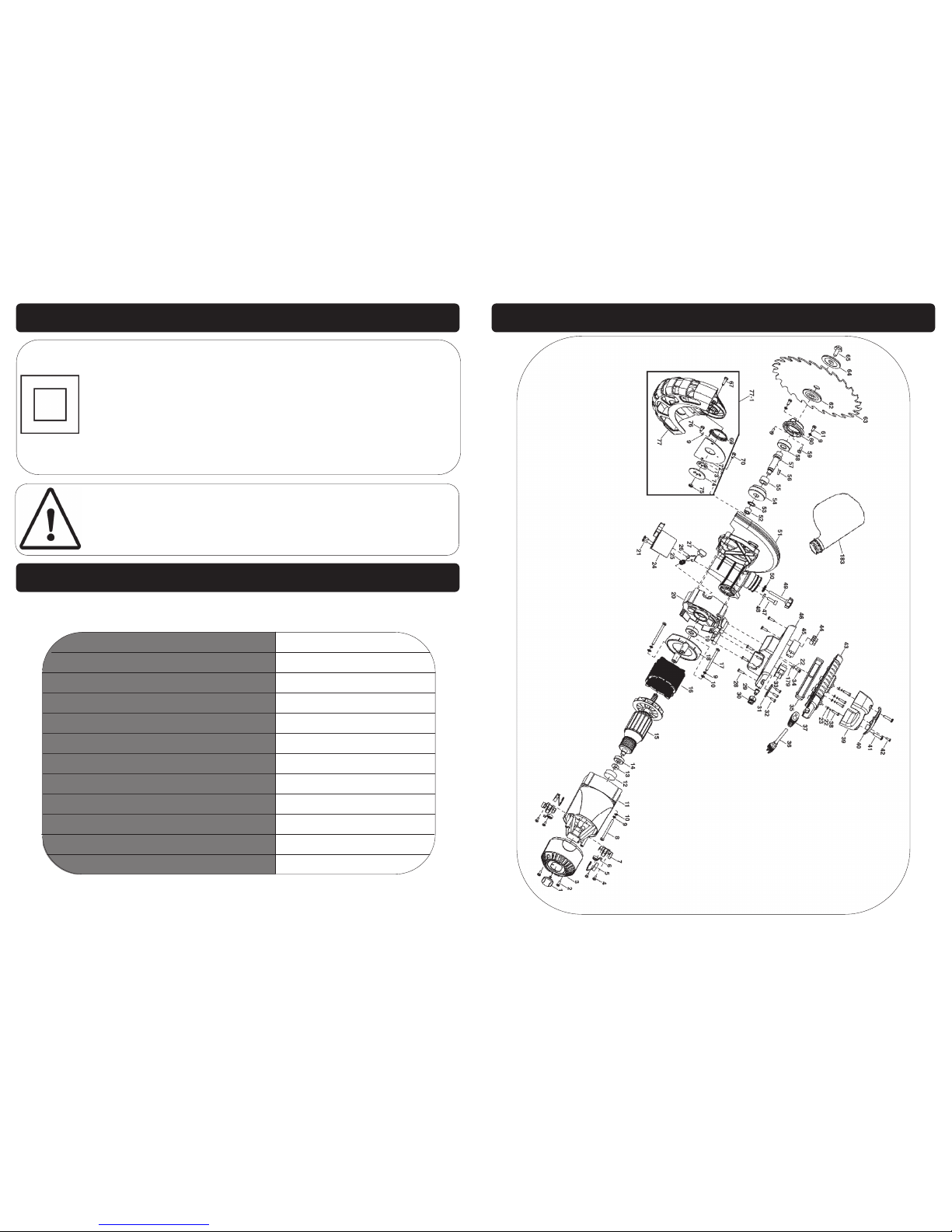
8
Caution: The warnings and cautions mentioned in this user manual can not
cover all possible conditions and situations that may occur. It must be understood by the operator that common sense and caution are factors which cannot be built into this product, but must be applied.
SAFETY INSTRUCTIONS...cont
TECHNICAL SPECIFICATIONS
Part number 01511
Input voltage 230v ~ 50hz
Power 2000 w
No load speed 5500 rpm
Blade Ø 254 mm
Blade bore 30 mm
Mitre table angles -45˚ - +45˚
Straight cut at 0˚x 0˚ 340mm x 80mm
Mitre cut at 45˚x 0˚ 240mm x 80mm
Bevel cut at 0˚ x45˚ 340mm x 50mm
Compound mitre cut at 45˚x 45˚ 240mm x 50mm
Weight 18kg
This mitre saw is double insulated; This means the operator is separated
from the tool's electrical system by two complete sets of electrical insulation. This extra layer of insulation is intended to protect the user from electrical shock due to a break in the wiring insulation. All exposed metal parts
are isolated from the internal metal motor components with protecting
insulation. Double insulated tools do not need to be grounded (earthed).
Servicing of a tool with double insulation requires extreme care and
knowledge of the system and should be performed only by a suitably
qualified person.
25
EXPLODED DRAWING A
Page 9
24
MAINTENANCE….cont
The motor of the saw should be cleared of any wood chippings as there would
be a risk of fire if they are allowed to build up over time (a soft brush or dry air
could be used to clear the motor).
Empty the bag at least after each use; the bag should be emptied before it
gets half full to ensure its efficiency. There is a zip on the bag to allow for easy
disposal of wood chippings.
Ensure the blade guard is kept clean with a damp cloth (do not clean the
guard or any part of the saw with a corrosive solvent) to reduce the risk of injury.
Periodically oil all the moving parts on the saw to extend the life of the saw.
Caution! Water must never come into contact with the tool.
9
This saw is fitted with a standard UK type 230v ~ plug. Before using the tool inspect the
cable and plug to ensure that neither are damaged. If any damage is visible have
the tool inspected / repaired by a suitably qualified person. If it is necessary to replace
the plug a heavy duty impact resistant plug would be preferable.
The wires for the plug are coloured in the following way:
Blue Neutral
Brown Live
As the colours of the wires may not correspond with the markings in your plug, proceed as follows:
The wire which is coloured blue, must be connected to the terminal marked
with N or coloured black.
The wire which is coloured brown, must be connected to the terminal, which is
marked L or coloured red.
Always secure the wires in the plug terminal carefully and tightly. Secure the cable in the cord grip carefully.
Note: Always make sure the mains supply is of the correct voltage and the
correct fuse protection is used. In the event of replacing the fuse always
replace the fuse with the same value as the original.
Warning: Never connect live or neutral wires to the earth terminal of the
plug. Only fit an approved plug with the correct rated fuse. If in doubt
consult a qualified electrician.
Note: If an extension lead is required in order to reach the mains supply;
ensure that this too is rated for the correct voltage and fuse rating.
Note: The cross section of the extension lead should be checked so that it
is of sufficient size so as to reduce the chances of voltage drops.
This mitre saw is double insulated. This means the operator is separated from
the tool's electrical system by two complete sets of electrical insulation.
ELECTRICAL CONNECTION
Page 10
10
This SIP 10” compound sliding mitre saw is covered by a 12 month parts and labour
warranty covering failure due to manufacturers defects. This does not cover failure
due to misuse or operating the saw outside the scope of this manual - any claims
deemed to be outside the scope of the warranty may be subject to charges Including, but not limited to parts, labour and carriage costs. Consumable items such as
fuses, blades and motor brushes are not covered by the warranty.
This saw is designed to ONLY cut wood or wood derived products.
In the unlikely event of warranty claims, contact your distributor as soon as possible.
Proof of purchase will be required before any warranty can be honoured.
Note: Proof of purchase will be required before any warranty can be honoured.
Note: If any parts are missing, contact your distributor for the missing parts
to be replaced.
Dust Bag
Work-piece Clamp
Blade Wrench
Instruction Manual
GUARANTEE
CONTENTS AND ACCESSORIES
23
Cleaning and maintenance of this saw is mainly common sense some points for
guidance are as follows:
Regularly check that all the fixing screws are tight, particularly the outer flange.
They may vibrate loose over time.
The mains lead of the saw and any extension cord used should be checked
frequently for damage. If damaged, have the mains lead replaced by an authorised service facility. Replace the extension cord if necessary.
Keep the air vents of the saw clear at all times.
After each use brush off any wood chippings with a soft brush. Pay special at-
tention to the inside of the dust extraction port (where the dust bag fits to the
saw) as this is where there will be a large build up if left for extended periods.
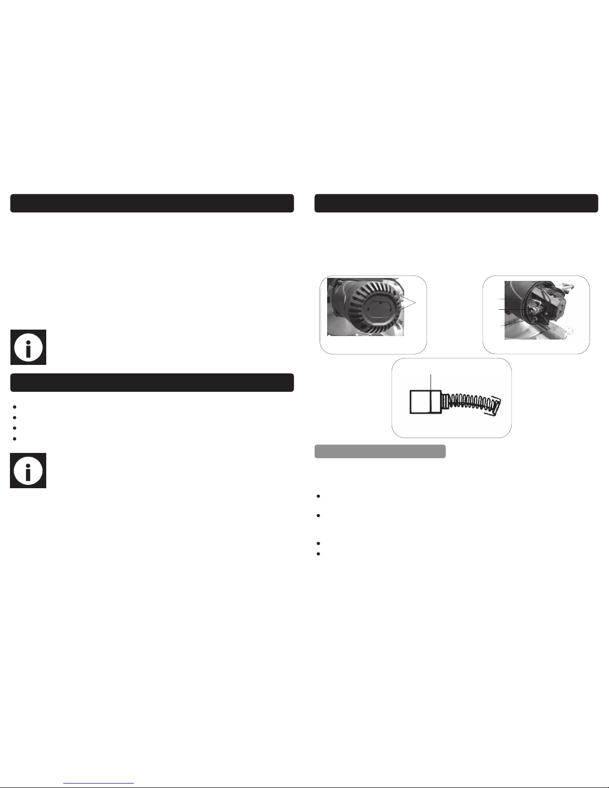
down to the limit mark, see Fig.6. Keep the carbon brushes clean and free to slip in
the holders.
If they have worn down to the limit mark, purchase a set of identical replacement carbon brushes (both carbon brushes should be replaced at the same time). Insert new
carbon brushes into the holders, connect them to the terminals, reposition the retaining spring and reinstall the motor housing cap using the 2 pan head screws.
MAINTENANCE….cont
Fig. 6
Limit Mark
A
Fig. 4
Fig. 5
B
C
D
GENERAL CLEANING
Page 11

22
Remove the outer blade flange and the blade.
Wipe a drop of oil onto the inner and outer blade flanges.
Fit the new blade onto the spindle, make sure that the blade has the appropriate dimensions and that the inner blade flange sits properly behind the blade.
MAINTENANCE….cont
24
Fig. 3
Reposition the outer blade flange.
Depress the spindle lock, reposition and secure the blade bolt using the blade
wrench; Tighten the blade bolt in a counter-clockwise direction as the blade
bolt has a left hand thread.
Follow the previous instructions in reverse to refit the blade guard etc.
Caution: Always install the blade with the blade teeth pointing downwards.
The direction of the blade rotation is also stamped with an arrow on the
blade guard.
Caution: Ensure all screws / bolts are completely tight and that the blade
guard works correctly before re-using the saw.
REPLACING THE CARBON BRUSHES
Remove and check the carbon brushes regularly (normally after 50 hours of use). The
carbon brushes are installed inside the motor housing. Using a screwdriver, remove
the 2 pan head screws (A) Fig.4 that hold the motor housing cap in place. Once the
motor housing cap is removed, release the carbon brush (C) Fig. 5 from the holder,
lower the retaining spring (D). Disconnect the carbon brush wire from the terminal (B),
remove the carbon brush from the motor housing and inspect it. Repeat this step for
the second carbon brush. Carbon brushes need to be replaced once they wear
11
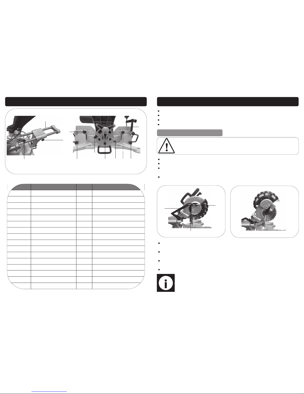
GETTING TO KNOW YOUR SAW
1
2 3
4
5
6
8
9
10
11
12
13
14
15
16
17
18
19
20
21
23
7
22
6
5
24
25
4
Page 12
12
GETTING TO KNOW YOUR SAW….cont
Ref. No. Description Description Ref. No.
1. Bevel Angle Pointer
Dust Collection Bag 17.
2. Bevel Angle Scale
Dust Collection Port 18.
3. Workbench Mounting Hole
Carrying Handle 19.
4. Work-piece Clamp
Operating Handle 20.
5. Depth Stop
On/Off Trigger Switch 21.
6. Sliding Rail
Blade Guard Release Lever 22.
7. Depth Stop Adjuster
Upper Blade Guard 23.
8. Spindle Lock
Motor 24.
9. Laser On/Off Switch
Lower Blade Guard 25.
10. Saw Head Release
Laser 26.
11. Sliding Rail Lock
Rear Fence Extension 27.
12. Fence Extension Lock
Rear Fence 28.
13. Side Rail Lock
Adjustable Side Rail Support 29.
14. Bevel Angle Adjust (90°)
Mitre Angle Lock 30.
15. Bevel Angle Lock
Mitre Angle Pointer 31.
16. Mitre Angle Scale 32. Bevel Angle Adjust (45°)
20
22
32
31
30
29
28
29
28
27
26
21
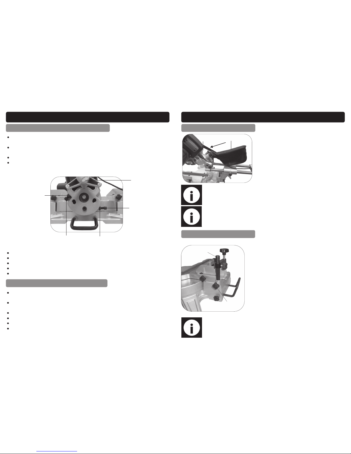
Pull on the saw head release knob (26) and turn it through 90˚ to lock it “open”
lift the operating handle (4) to its full height.
Unscrew and remove large screw (A) Fig.1, and move the blade guard pivot link
arm (B) out of the way.
Unscrew and remove pan head screw (C) which fixes the guard plate and lower
blade guard to the upper blade guard.
MAINTENANCE….cont
Loosen the locking nut on the bevel angle adjust bolt (45°) (32).
Turn the angle adjust bolt (32) until an angle of 45° is achieved.
Lock off the locking nut whilst ensuring that the angle kept.
Check if the bevel angle pointer is pointing to 45° and adjust as necessary.
CHANGING / INSTALLING THE BLADE
Caution: Always ensure that the replacement blade matches the specifications, as shown on page 8. Never fit a blade which is smaller or bigger
than that stated.
A
B
C
Fig. 1
Once the pan head screw (C) is removed, swing the guard plate and lower
blade guard upwards to allow access to the blade bolt as shown in Fig.2.
Completely depress the spindle lock button (24) Fig. 3, page 22 using one
hand.
Whilst keeping the spindle locked; Rotate the blade by hand until the spindle
locks.
Use the supplied blade wrench to remove the blade retaining bolt.
Fig. 2
Note: loosen in a clockwise direction as the blade bolt has a left hand
thread.
Page 13
20
Loosen the sliding rail lock (27); push the saw head back as far as it will go and
re-tighten the sliding rail lock (27).
Loosen the mitre lock (14); turn the main table until the positive stop for 0° engages and the angle guide pointer shows 0°.
Re-tighten the mitre lock.
Place a 90° square against the blade and the table; If the angle is not exactly
90°.
Loosen the locking nut on the bevel angle adjust bolt (90°) (30).
Loosen the bevel angle lock (31).
Turn the angle adjust bolt (30) until an angle of 90° is achieved.
Lock off the locking nut whilst ensuring that the angle kept.
Check if the bevel angle pointer is pointing to 0° and adjust as necessary.
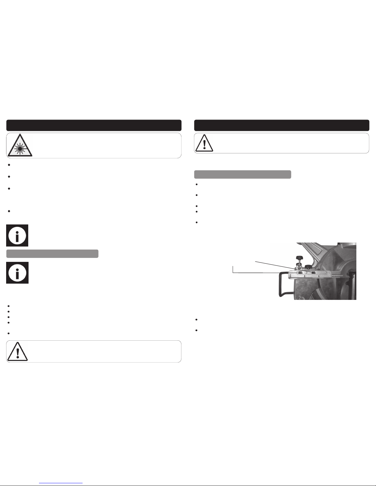
CHECKING AND SETTING THE BEVEL ANGLE @ 90°
MAINTENANCE….cont
32
30
Locking Nut
Locking Nut
31
Loosen the sliding rail lock (27); push the saw head back as far as it will go and
re-tighten the sliding rail lock (27).
Loosen the mitre lock (14); turn the main table until the positive stop for 0° engages and the angle guide pointer shows 0°.
Re-tighten the mitre lock.
Loosen the bevel angle lock (31).
Push the saw head as far to the left (to 45°) as it will go.
Place a set square with an accurate 45° angle against the main table of the
saw and the blade; If the angle is not exactly 45°.
CHECKING AND SETTING THE BEVEL ANGLE @ 45°
13
Note: For efficient operation, empty the dust bag when it is no more than
half full, this allows better air flow through the bag.
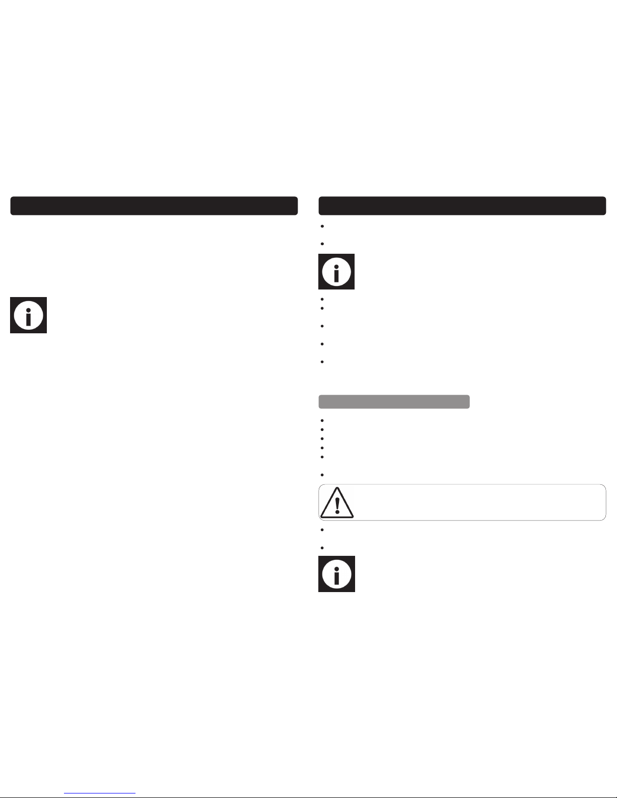
FITTING THE DUST COLLECTION BAG
ASSEMBLY INSTRUCTIONS
FITTING THE WORK-PIECE CLAMP:
Fit the dust collection bag (1) into the dust collection port (2).
Note: For more efficient dust removal; The dust bag should be removed
and a separate dust extractor could be used.
The work-piece clamp (20) can be fitted to either
side of the saw blade depending on the workpiece size and the type of cut being performed.
Slide the column of the clamp into the clamp
retainer and secure by tightening the thumbscrew.
Note: The height and depth etc. of the clamp should be set according to
the work-piece / type of cut being performed.
1
2
20
Thumbscrew
Page 14
14
Do not stare directly at the laser beam, never aim the beam at any person or
an object other than the work-piece.
Do not deliberately aim the beam at people or animals, particularly towards
the eyes.
Do not use the laser if the work-piece has reflective surfaces. Wood or rough
coated surfaces are acceptable, bright shiny reflective surfaces are not suitable
for laser use as the reflective surface could direct the beam back at the operator.
Always remember to switch off the laser on/off switch (25) after finishing the job;
only turn the laser beam on when the work-piece is on the mitre saw table.
Note: When cutting a narrow piece of wood it is not necessary to use the
slide mechanism; In these cases ensure that the saw head is pushed back
and the slide lock (27) is tight to prevent the saw arm from sliding.
A crosscut is made by cutting across the work-piece; a 90˚crosscut is made with the
mitre table set at 0˚. Mitred crosscuts are made with the table set at any other angle.
Pull on the saw head release knob (26) and turn it through 90˚ to lock it “open”.
lift the operating handle (4) to its full height.
Loosen the mitre angle lock (where applicable) (14).
Rotate the mitre table until the pointer (15) aligns with the desired angle on the
scale (16).
Retighten the mitre angle lock (14).
Note: When cutting long pieces of timber use the side rail supports, if cutting extra long timber, a roller stand or a work surface that is level with the
saw table should be utilised.
Warning: Do not stare into the laser beam as this is dangerous and will
damage your eyes.
OPERATING INSTRUCTIONS
CROSS-CUTTING (WITHOUT SLIDE ACTION)
Warning! Ensure the mitre lock is fully tightened before making a cut; Failure
to do so could result in the table moving during the cut and cause serious
personal injury, and damage the work-piece / saw.
19
This saw is set up at the factory and should need no adjustment; however time and
careless use can affect the angles and some adjustment may be required.
Loosen the sliding rail lock (27); push the saw head back as far as it will go and
re-tighten the sliding rail lock (27).
Loosen the mitre angle lock (14); turn the main table until the positive stop for 0°
engages and the mitre angle pointer (15) is close to 0°.
Re-tighten the mitre angle lock (14).
If the mitre angle pointer (15) is not exactly set to 0° loosen the screw and turn
the pointer until it is.
Loosen the 4 (2 on each side of the saw) rear fence locking bolts and lower the
blade to its lowest point; lock the saw head down with the saw head release
(26).
Place a square against the blade and rear fence and adjust the fence until an
angle of exactly 90° is achieved.
Proceed to tighten the rear fence locking bolts whilst ensuring that an angle of
90° is maintained.
Rear Fence Locking Bolts
MAINTENANCE
Warning! Always ensure that the saw is turned off and that the plug is disconnected
from the mains supply before carrying out any adjustments, repairs or maintenance.
CHECKING AND SETTING THE MITRE ANGLE
Page 15
18
Note: It may be necessary to clean the slot with a sharp chisel or by sand-
ing.
OPERATING INSTRUCTIONS….cont
Function:
Once the depth stop is set; the blade will not cut all the way through the work-piece
(depending on the depth that it is set to). This will allow the operator to easily cut slots
out of the work-piece if used in conjunction with the sliding function of the saw.
it is advisable to check the cut depth on a scrap piece of wood.
Set the required angles etc. and proceed to cut as explained earlier in this manual.
15
Unscrew the sliding rail lock (27).
Pull on the saw head release knob (26) and turn it through 90˚ to lock it “open”
Lift the operating handle (4) to its full height and slide (pull) it towards you.
Loosen the mitre angle lock (where applicable) (14).
Rotate the mitre table until the pointer (15) aligns with the desired angle on the
scale (16).
Retighten the mitre angle lock (14).
Place the work-piece flat on the table with one edge securely against the fence
(12).
Use the clamp assembly (20) to secure the work-piece.
Note: The work-piece clamp (20) can be fitted to either side of the saw
blade depending on the work-piece size and the type of cut being performed; Always ensure the clamp is secure before operation.
OPERATING INSTRUCTIONS….cont
Turn on the laser by pressing the laser On/Off switch (25).
Hold the operating handle (4) firmly and squeeze the trigger switch (5); allow the
blade to reach maximum speed.
Press the blade guard release lever (6) and slowly lower the blade onto and
through the work-piece.
Release the trigger switch (5) and allow the saw blade to stop rotating before
raising the blade away from the work-piece.
Ensure that the blade has stopped and that the saw head is returned to a position so that the guard is covering the blade before removing the work-piece
from the table.
CROSS-CUTTING (WITH SLIDE ACTION)
Place the work-piece flat on the table with one edge securely against the fence
(12).
Use the clamp assembly (20) to secure the work-piece.
Warning! Ensure the mitre lock is fully tightened before making a cut; Failure
to do so could result in the table moving during the cut and cause serious
personal injury, and damage the work-piece / saw.
Note: The work-piece clamp (20) can be fitted to either side of the saw
blade depending on the work-piece size and the type of cut being performed; Always ensure the clamp is secure before operation.
Page 16
16
A bevel cut of up to 45° (to the left) can be achieved by using the following method:
Loosen the bevel lock handle (31) which is situated at the rear of the saw.
Use the bevel angle scale (18) and pointer (17) to set the head to the desired
angle.
Tighten the bevel lock handle (31) to secure the head at the desired angle.
Follow the previous instructions to perform the cut depending on the dimensions of
the work-piece (see “cross cut with sliding action” or “cross cut without sliding action”).
A mitred angle of 45° left or right can be obtained using the following method.
Loosen the mitre angle lock (14).
Turn the table until the desired angle is indicated by the mitre angle pointer (15)
on the mitre angle scale (16).
Tighten the mitre lock (14) to hold the desired angle.
Follow the previous instructions to perform the cut depending on the dimensions of
the work-piece (see “cross cut with sliding action” or “cross cut without sliding action”).
Note: The mitre angle guide has positive stops at popular angles 15°,
22.5°, 30° & 45° left and right, but any angle between 0° and 45° can be
selected by tightening the mitre lock at the desired angle (14).
OPERATING INSTRUCTIONS….cont
Turn on the laser by pressing the laser On/Off switch (25).
Hold the operating handle (4) firmly and squeeze the trigger switch (5); allow
the blade to reach maximum speed.
Press the blade guard release lever (6) and slowly lower the blade onto and
through the work-piece whilst sliding (pushing) the handle away from you at the
same time until the work-piece is cut.
Release the trigger switch (5) and allow the saw blade to stop rotating before
raising the blade out of the work-piece.
Ensure that the blade has stopped and that the saw head is returned to a position so that the guard is covering the blade before removing the work-piece.
MAKING A BEVEL CUT
MAKING A MITRE CUT
17
A compound mitre cut involves using a mitre angle and a bevel angle at the same
time. It is used in making picture frames, to cut mouldings, making boxes with sloping
sides and for roof framing. Use the slide action when cutting wider work-pieces.
Follow the previous instructions to set both angles and to complete the cut.
MAKING A COMPOUND MITRE CUT
OPERATING INSTRUCTIONS….cont
Note: It is a good idea to make a test cut on a piece of scrap wood before cutting into the good material.
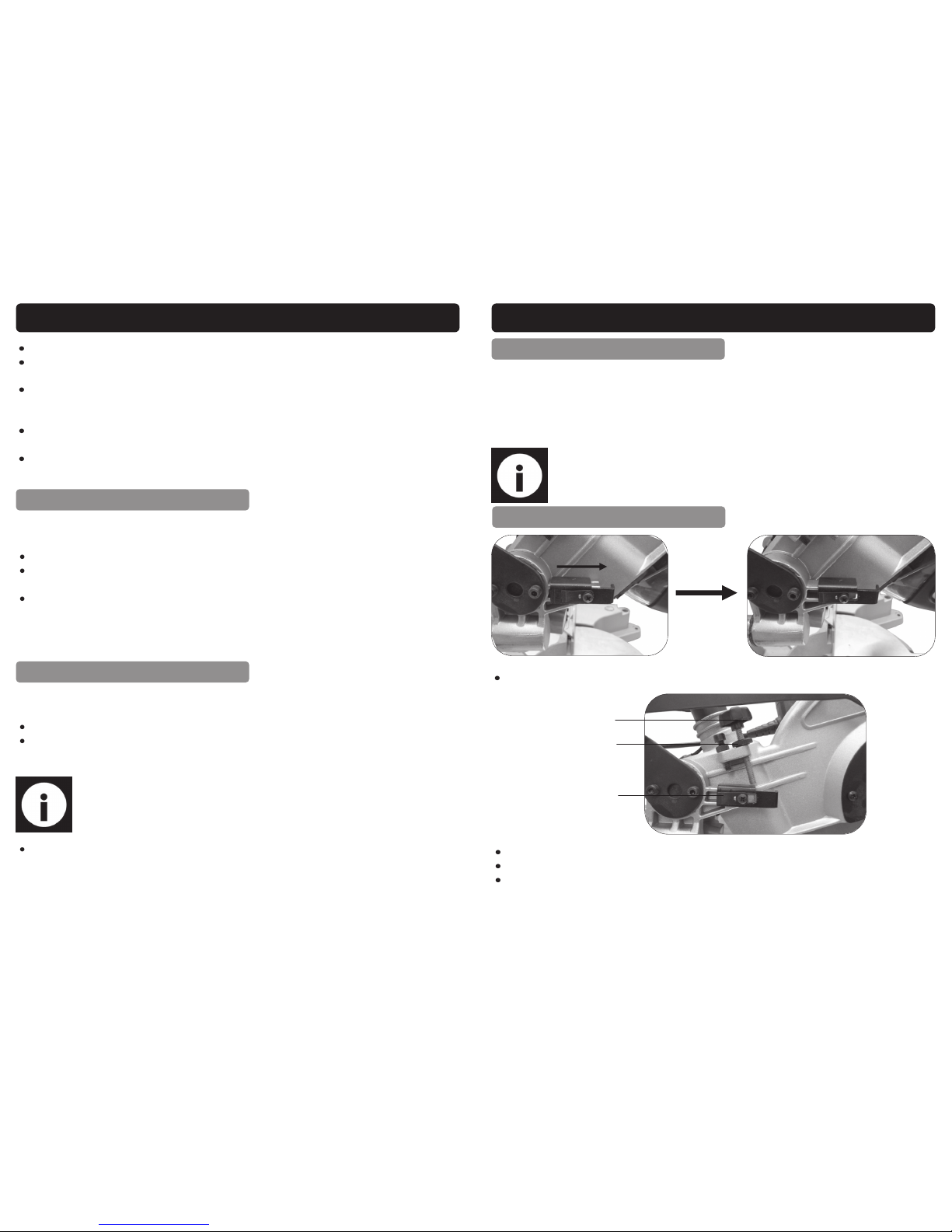
USING THE DEPTH STOP
Slide the depth stop bracket (21) to the right to engage the depth stop.
Lock-nut
Screw
Bracket
Loosen the lock-nut.
Adjust screw to the required depth.
Once set to the desired depth; Tighten the lock-nut against the retaining bracket to lock the depth stop and ensure there is no movement due to vibration etc.
 Loading...