

Page 1
28
FOR HELP OR ADVISE ON THIS PRODUCT PLEASE CALL OUR
CUSTOMER SERVICE HELP LINE : 01509 500359
Please dispose of packaging for the product in a responsible
manner. It is suitable for recycling. Help to protect the
environment, take the packaging to the local amenity tip and
place into the appropriate recycling bin.
Never dispose of electrical equipment or batteries in with
your domestic waste. If your supplier offers a disposal facility please use it or alternatively use your local amenity tip
and dispose in the correct manner. This will allow the recycling of raw materials and help protect the environment.
1
01321
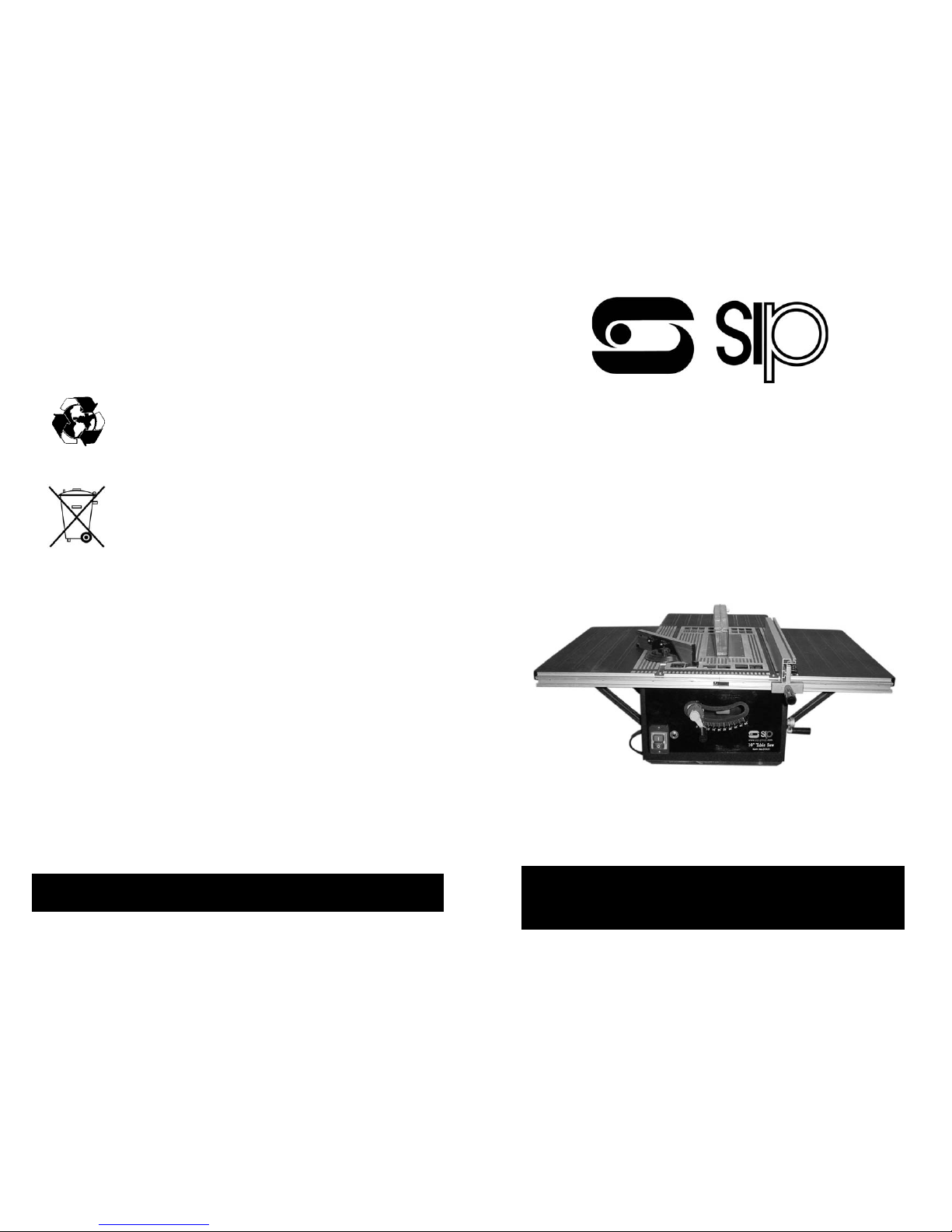
Table Saw
Please read and fully understand the instructions in this
manual before operation. Keep this manual safe for
future reference
Page 2
2
Pic 1.
27
DECLARATION OF CONFORMITY
DECLARATION OF CONFORMITY
WE
SIP LTD
GELDERS HALL ROAD
SHEPSHED
LOUGHBOROUGH
LEICESTERSHIRE
LE12 9NH
Declare that the
Trade Table Saw SIP Pt No: 01321
Complies with the following EEC Directives their supporting Statutory
Instruments and the relevant standard where applicable:
98/37/EEC Machinery Directive
73/23/EEC Low Voltage Directive
EN 61029-1
EN 61029-2-1
89/336/EEC EMC Directive
EN 55014-1
EN 61000-3-2
EN 61000-3-3
EN55014-2
Signed:
Joint Managing Director
Date: 5th February 2004
Page 3
26
NOTES.
3
Page 4
4
25
NOTES.
Page 5
24
NOTES.
5
Page 6
6
23
Page 7
22
WOODWORKING TERMINOLOGY:
Work Piece.
The Item on which the cutting operation is being performed.
Kickback.
An uncontrolled grabbing, and throwing of the work- piece back toward the front of the saw during a
rip type operation.
Leading edge.
The end of the work piece which, during a rip type operation Is pushed into the cutting tool first.
Moulding.
A non-through cut which produces a special shape in the work piece used for Joining or decoration.
Push Stick.
A device used to feed the work piece through the saw during narrow ripping type operations. helps
keep the operators hands well away from the blade.
Anti-kickback pawl s.
Device which, when properly installed and maintained, Is designed to stop the work piece from being
kicked back at the operator during operation.
Push Block.
A device used for ripping type operations too narrow to allow use of a push stick.
Arbor.
The shaft on which the blade Is mounted.
Crosscut.
A cutting or shaping operation made across the grain of the work piece.
Dado.
A non-through cut which produces a square sided notch or trough in the work- piece.
Feather Board.
A. device which can help to guide the work piece and holds it against the table and or fence during
the cutting operation.
Gum.
A sticky, sap based residue from wood products.
Heel.
Misalignment of the blade.
Kerf
A notch, channel, or slit made in any material by cutting or sawing.
Rebate.
A notch in the edge of a work piece.
Resin.
A sticky, sap based substance that has hardened.
Ripping.
A cutting operation along the grain of the work piece.
Rotational speed.
The number of turns completed by a spinning object in one minute.
Riving Knife.
Positioned behind the saw blade to prevent work-piece closing and jamming after being cut.
7
Page 8
8
21
PROBLEM POSSIBLE CAUSE REMEDY
The saw does not make accurate 45º or 90º cross cuts.
Mitre gauge is out of alignment. Check and adjust the mitre
gauge.
The motor fails to start but the
electrical supply is ok.
Faulty ON/OFF Switch.
Windings in the field armature
burned out or damaged.
Circuit breaker is too sensitive.
Have the switch checked / replaced by an authorised service
centre.
Have the motor checked / replaced by an authorised service
centre.
Use a less sensit ive circuit
breaker.
The motor overheats, stalls,
trips the circuit breaker or
blows fuses.
Motor is overloaded.
Sawdust build up around the
motor causing it to overheat.
Windings burnt out.
Circuit breakers or fuses do not
have Sufficient capacity.
Feed work piece slower into
blade.
Use a brush or suitable vacuum
cleaner to remove dust and dirt
to increase the air- flow to the
motor.
Have the circuit breakers or
fuses checked by an electrician
to ensure they are of the correct capacity.
Cutting stalls the motor.
Blade burns the work piece.
Blade stops when rip cutting.
Dull blade.
The blade is heeling.
The feed rate is too fast.
The blade is not parallel to the
blade or mitre gauge groove.
Riving knife is out of alignment.
Replace the blade.
See the section on blade adjustment.
Slow down the the rate of feed.
See the section on rip fence
adjustment
See the section on riving knife
adjustment.
NOTE: In all cases, where an electrical problem occurs. Isolate the machine
from the mains supply and remove the plug from the mains socket before
consulting a qualified electrician. To ensure safety and reliability, with the
exception of replacing carbon brushes all repairs should be carried out by an
authorized service centre.
Page 9
20
PROBLEM POSSIBLE CAUSE REMEDY
The saw will not start Saw is not plugged in and
switched on
Fuse blown, circuit breaker or
(RCD) has tripped.
Plug in and switch on Replace fuse or reset circuit breaker or (RCD}.
Does not make accurate 45º or
90º rip cuts.
Tilt stops not adjusted correctly
Tilt pointer not set at accurately.
Check the blade using a set
square and adjust the stop
correctly. Adjust the pointer to
0º.
The material pinches the blade
when ripping.
Rip fence is not aligned with
the blade.
Warped material (the edge
against the rip fence Is not
straight).
Check alignment of blade and
adjust: if required.
True up uneven edge. Select
another piece of material.
The material binds on the riving
knife.
The riving knife is not correctly
aligned with the blade.
The blade set Is narrower than
the riving knife.
Check the alignment of the
riving knife and adjust: if required.
Select another blade.
The material is kicked back
from the blade.
The rip fence is out of alignment.
The riving knife is not aligned
with the blade or not fitted
Feeding the material without
using the rip fence.
Releasing the material before
the cut is completed.
A dull blade.
The mitre gauge locking knob is
not tightened.
Check the alignment of the rip
fence and adjust: if required.
Check the alignment of the
riving knife and adjust if required.
Install the rip fence.
Feed the material all the way
through before releasing it.
Replace the blade.
Secure the locking knob.
The saw makes an unsatisfactory cut.
Dull blade.
Blade is mounted backwards.
Gum or pitch build up on the
blade.
Incorrect blade for the operation.
Gum or pitch build up, causing
erratic feed.
Replace the blade.
Mount the blade the correct
way round.
Remove the blade and clean
with suitable cleaner and steel
wool.
Use the correct blade.
Clean the table with a suitable
cleaner.
The blade does not raise or tilt
smoothly.
Sawdust and dirt in the mechanism
Use a brush or suitable vacuum
cleaner to remove dust and dirt
and lubricate .
The blade does not run up to
speed.
Extension reel not of the correct
rating or is too long.
Use the correct extension reel,
if unsure contact an electrician.
Excessive vibration. The saw is not mounted cor-
rectly.
The stand or bench is on an
uneven ground.
Damaged or bent saw blade.
Check the mounting and secure
mount fixings.
Secure bench or stand on a
level surface.
Replace the blade.
Trouble shooting:
9
Page 10
10
Electrical information 13Amp Class 1 Protection
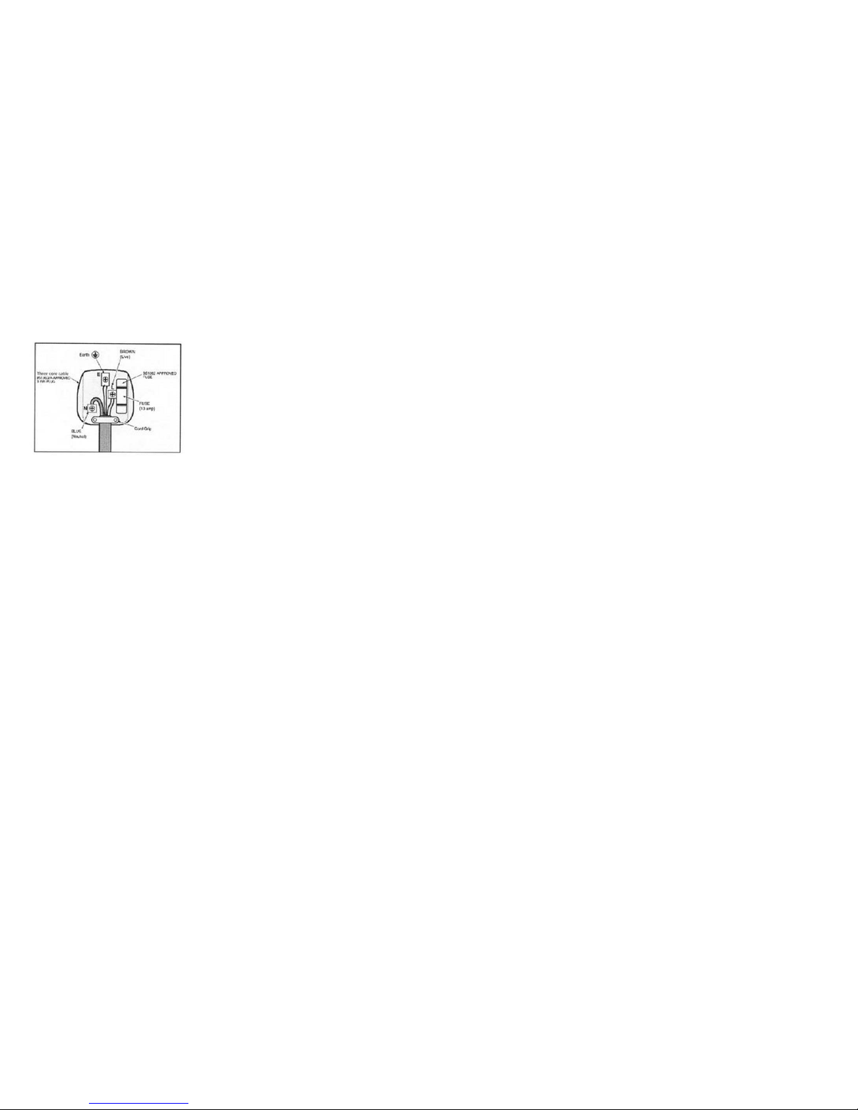
CONNECTION OF THE MAINS PLUG
Important! The wires in the mains lead fitted to this product are coloured in
accordance with the following code:
Brown: live (L) or Red
Blue: Neutral (N) or Black
Green and Yellow or Green: Earth (E)
THIS PRODUCT REQUIRES A CONNECTION
TO EARTH. THE 3 PIN PLUG MUST COMPLY
TO BS1363/ A. The FUSE MUST COMPLY TO
B51362
If for any reason the 13 amp plug fitted to this product requires replacing it must be wired in accordance with the following instruction:
Do not connect the brown (live) or blue (neutral) to the earth pin MARKED E on
the 3 pin plug.
Connect the Blue wire to the terminal marked Neutral (N).
Connect the Brown wire to the terminal marked live (L).
Connect the Green and Yellow wire to the terminal marked Earth E.
Ensure that the outer insulation is gripped by the cord grip and that the wires
are not trapped when replacing the plug cover. The mains lead on this product is
fitted with a 13 amp (BS1363/A) plug. A 13 amp (B51362) fuse must be fitted in
the plug. If in doubt consult a qualified electrician.
There are no user serviceable parts inside this product except those referred to
in this manual. Always refer servicing to qualified service personnel. Never remove any part of the casing unless qualified to do so; this unit contains dangerous voltages.
WARNING!
For your protection if this tool is to be used outdoors, do not expose it to rain or
use it in damp locations. Do not place the tool on damp surfaces, use a workbench if available. For added protection use a suitable residual current device (R.
C.D.) at the socket outlet.
If an extension cable is to be used with this machine it must be of 3 core construction with the earth conductor connected at both the plug and socket. If in
doubt consult a qualified electrician.
19
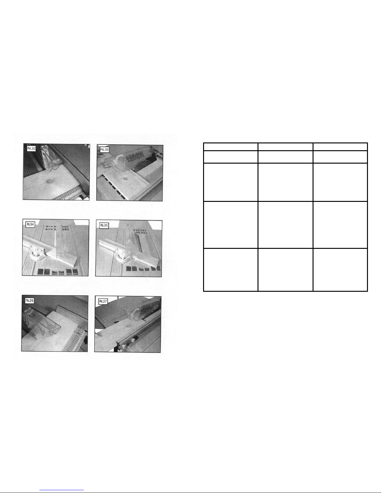
Using the rip fence. (Pic 37)
Ripping, bevel ripping, and rebating are done using the rip fence.
Ripping.
Ripping is cutting a piece of wood with the grain or lengthwise (Pic 37).
This is done using the rip fence. Position the rip fence to the desired width of the rip and lock it in place. Before starting to cut be sure that the rip fence is parallel to the saw blade, and that the riving knife is correctly
aligned with the saw blade. When ripping long boards or large panels always use a work support. Hold the
piece against the fence and feed it through the blade with a smooth, steady pressure.
When the ripping width is wider than 150 mm (6") ,
use your right hand to feed the work piece until it is clear of the table. Use your left hand only to guide, not to
feed the work piece.
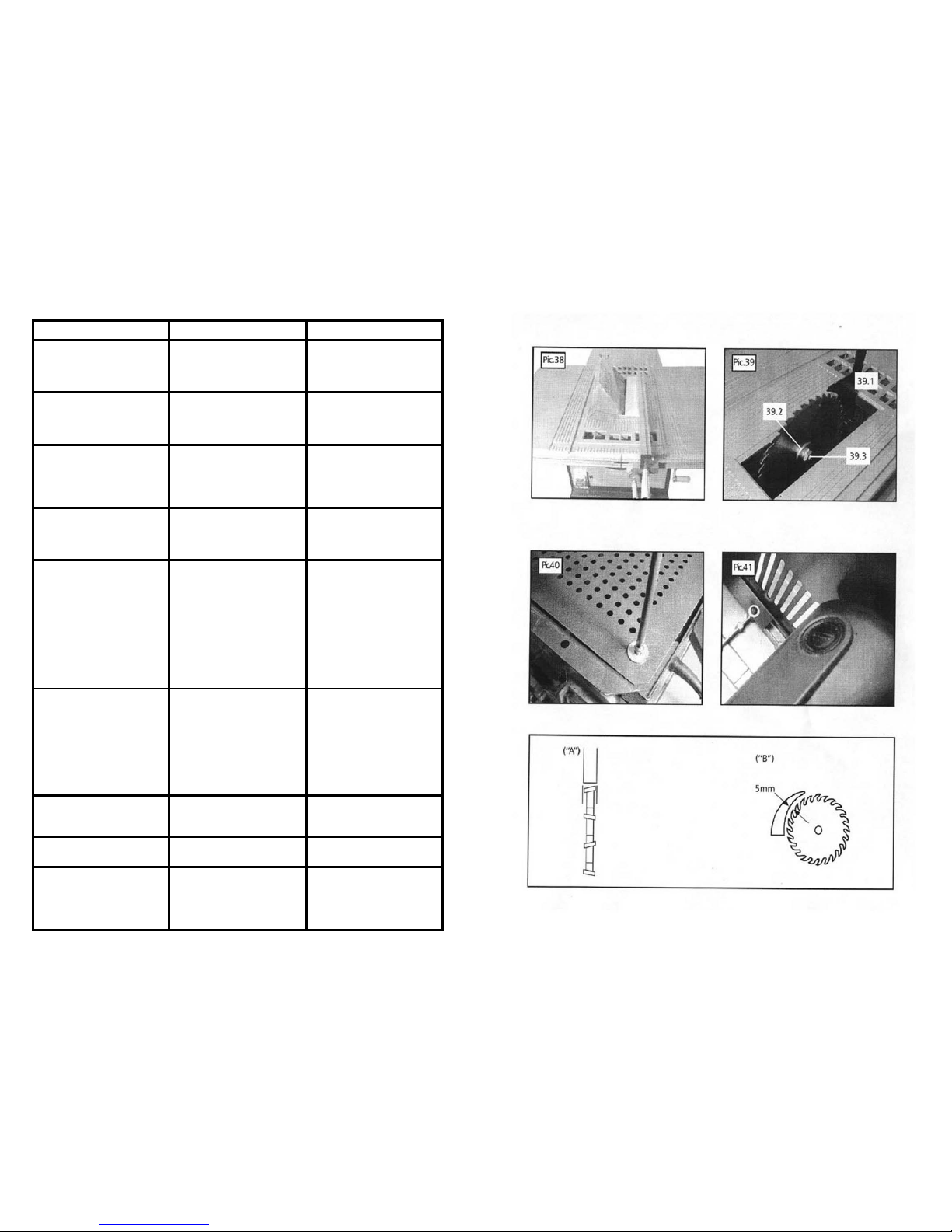
Bevel cutting. (Pic 38)
When bevel cutting material 150mm (6") or narrower use the fence on the right side of the blade only (Pic
38).
Blade Replacement (Pic 39)
Remove the blade guard and the table insert. Fully release the lock handle and turn the elevating handle in a
clockwise direction to raise the blade to its highest position. Remove the blade fixing nut (pic 39, 39.3) and
the outer flange (pic 39, 39.2) and remove the blade. Ensure that the motor shaft, blade mounting arbor,
inner and outer flanges and the securing nut are dean and free from sawdust build up. Fit the new blade (Be
sure that the teeth are facing downwards when viewed from the front of the machine). Ensure that the
flanges are clean and fitted the correct way round. Secure the blade in place by using the securing nut, Re-fit
the table insert and secure in place with the cross head screws. Re-fit the blade guard ensuring that it oper-
ates correctly.
Check the alignment of the riving knife as detailed In the specific safety instructions.
Before switching the table saw ON, make sure the blade guard is installed and operating correctly.
Check that the blade is set to 90° and at its lowest position.
Ensure that the table is clear of any tools or other mater ials.
Ensure that all nuts, bolts and other fastenings are secure.
If the machine makes any unusual noise or vibrates excessively, STOP the machine immediately and investigate the cause and rectify. If the cause cannot be identified NO NOT use the machine and contact your nearest service centre.
Lubrication. (Pic40)
Before lubricating, remove the bottom safety cover by removing the cross head pan screws. Lubricate the
blade tilting operating screw and both pairs of locking and adjustment nuts and the blade elevating threaded
rod once a month using a light machine oil or other similar lubricant.
Maintenance
Do not make any adjustment while the motor is in motion. Always make sure the machines plug has been
removed from the mains power source before changing brushes, lubricating or when doing any work or maintenance on the machine. After each use, check your machine for damage or broken parts and keep it in top
working condition by repairing or replacing parts immediately, clean out accumulated dust.
During use the carbon brushes will wear down, this will be indicated by a possible loss of power and excessive
sparking seen through the ventilation slots. When the brushes have worn down to approximately 4-5mm they
will require replacing. Remove the two round cover plates, one on either side of the motor casing (Pic 41).
Remove the worn carbon brush and replace it with the new one, and re-fit the round cover plate. Repeat this
operation for the other carbon brush.
NOTE: Carbon brushes must always be changed as a pair.
Caution: If you are unsure or if safety critical repairs are required always refer the saw to a qualified engi-
neer/service centre.
Page 11

18
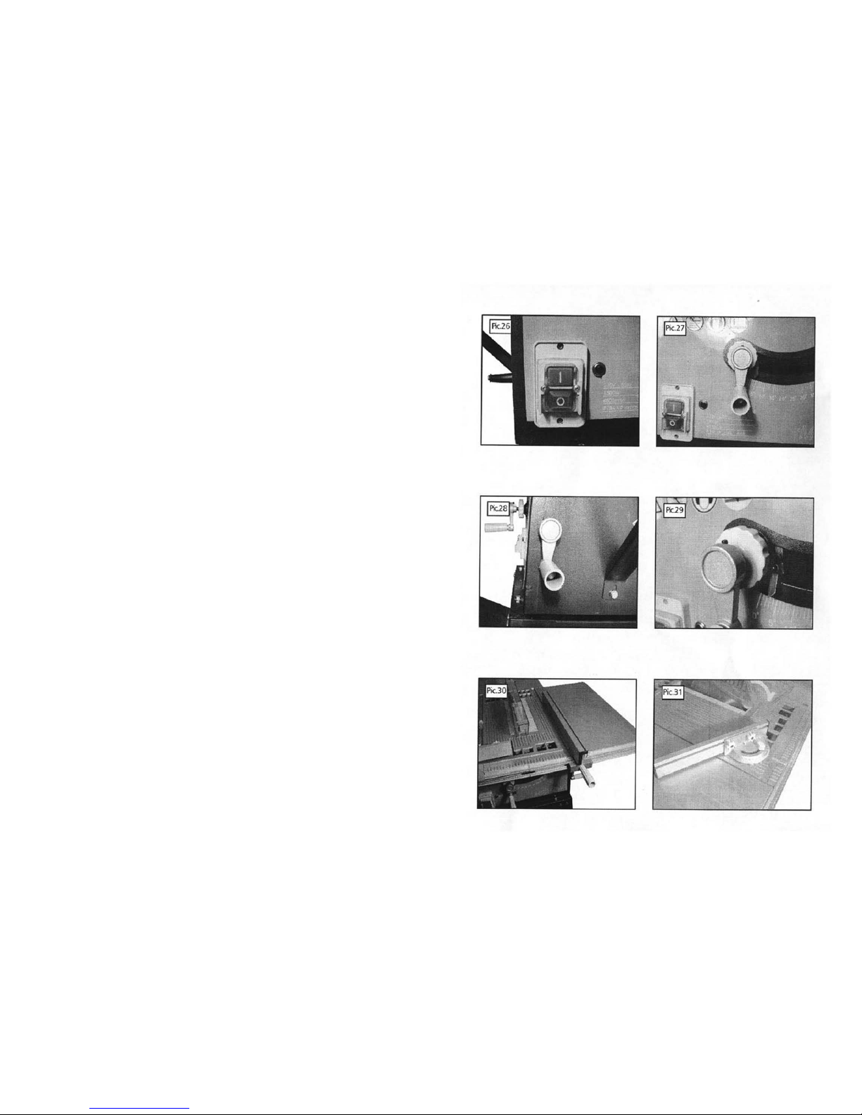
The locking knob. (Pic 29)
The locking knob is used to lock the required blade height and tilt posit ions. To loosen the locking knob turn
it counter clockwise. Before turning the table saw on, be sure that the locking knob is securely tightened so
that the blade will not shift during the table saw operation.
The riving knife. (See Specific safety instructions for correct setting)
The riving knife ensures that when a cut is made, the two pieces of timber on either side of the blade do not
close up onto the blade. This prevents possible binding and kickback.
The rip fence. (Pic 30)
The rip fence is used to guide the material when making long cuts, usually cutting along the grain NEVER
rip freehand without the fence in place and securely locked.
The mitre gauge. (Pic 31)
The mitre gauge is typically used to guide the work piece when cross cutting (across the grain) and can be
set to cut at various angles. It can be used in either of the grooves machined in the table. Always ensure
that it is locked securely when in use.
Cross cutting. (Pic 32)
Cross cutting is cutting wood across the grain at 90° or square with both the edge and the flat side of the
wood.
Mitre cross cutting. (Pic 33)
Mitre crosscutting is cutting the wood at an angle other than 90° with the edge of the wood. Follow the
same procedures as you would for crosscutting. But adjust the mitre gauge to the desired angle.
Bevel cross cutting. (Pic 34)
Bevel cross cutting is the same as cross cutting except that the wood is also cut at an angle other than at
90° with the flat side of the wood. Follow the same procedures as you would for cross cutting. But adjust
the blade to the desired angle. Use the mitre gauge in the groove to the right of the blade to avoid the blade
guard from interfering with the cut.
WARNING!
When cross cutting, mitre cutting, bevel cutting and when rebating across the end of a narrow work piece
always use the mitre gauge. NEVER make these cuts freehand (not using the mitre gauge or the other devices) because the blade could bind causing a kickback or causing your hand or fingers to contact the blade.
ALWAYS lock the mitre gauge when in use. Remove the rip fence from the table when not in use.
make sure the blade safety guard is mounted for all through sawing operations (the blade cuts through the
entire thickness of the work piece). The blade should extend approximately 3.5mm (1/ 8") above the top of
the work piece.
Compound mitre cutting. (Pic 35) Compound mitre cutting is a combination of mitre cutting and bevel
cross cutting.
The cut is made at an angle other than 90° to both the edge and the flat side of the wood.
Adjust the mitre gauge and the blade to the desired angle and be sure that the mitre gauge is locked.
Repetitive cutting. (Pic 36)
Repetitive cutting is cutting a number of pieces the same length, without having to mark each piece. The
safe way to perform repetitive cutting, is to set the rip fence to give the required length, and to be dear of
the front of the blade (Pic 36). When the cut is made, the end of the work piece is dear of the rip fence but
at the required length.
11
GENERAL SAFETY INSTRUCTIONS:
Before attempting to operate this machine, it is important that you read, understand and follow these instructions very carefully. They are designed for the safety of yourself and others ensuring a long and trouble free
service life from your machine.
SAFE OPERATION:
Know Your Power Tool:
It is important that you read and understand your instruction manual and any label attached to the power
tool. Learn its applications as well as its limitations and the potential hazards associated with this power tool.
Work Area:
Cluttered benches and work areas invite accidents. Workbenches should be kept tidy. Floors should be kept
clean and free from rubbish. Special care should be taken where the floor is slippery due to sawdust or wax.
Work Environment:
Do not expose your power tools to rain or use in damp or wet locations. Keep the work area well lit. Do not
use power tools in areas where there is a risk of explosion or fire from combustible materials, flammable
liquids, paint, varnish, petrol etc. flammable gases and dust of an explosive nature. As a precaution it is
recommended that you consult an expert on a suitable fire extinguisher and its use.
Guard Against Electric Shock:
Avoid body contact with earthed or grounded surfaces (e.g. pipes, radiators, ranges, and refrigerators).
Beware Children and Pets:
Children and pets should be kept out of the work area. Children should not be allowed to touch or operate
machinery or touch extension cords. All power tools should be kept out of the reach of children, preferably
stored or locked in a secure cabinet or room when not in use.
Do Not Force the Power Tool:
The power tool will do a better and safer job and give you much better service if it is used at the rate for
which it was designed.
Use the right tool:
Select the right tool for the job. Do not use a tool for a job for which it was not designed. Do not force a small
tool to do the job of a heavy-duty tool. Do not use tools for purposes not intended; for example do not use a
circular saw to cut tree limbs or logs.
PERSONAL SAFETY:
Clothing
Do not wear loose clothing, jewellery or anything that could get caught in moving machinery.
Hair:
Long hair should be tied back or contained in a protective covering.
Eye Protection:
The use of safety goggles is a mandatory requirement (normal glasses are not sufficient for eye protection).
Prescription spectacles do not have safety lenses.
Ear Protection:
Ear protection is advised during periods of extended operation.
Footwear:
Where there is a risk of heavy objects damaging feet or if there is a risk of slipping on wet or slippery floors
suitable non-slip safety footwear should be worn.
Head Protection:
Where there is a risk of falling objects or hitting your head on protruding or low level obstructions a hard hat
should be worn.
Page 12

12
Respiratory Protec tion
When the machining operation creates dust, wear a dust mask. When machining man made fibre
boards, especially MDF (Medium Density Fibre Board) the resin used in these materials can be hazardous to your health. Use an approved face mask with replaceable filter.
Dust Extraction Equipment
If the machine is fitted with dust extraction and collection facilities ensure that these are properly
connected and used.
Do Not Abuse the Power Cord
Never yank or pull on the power cord to disconnect it from the mains supply socket. Never carry your
power tool by its power cord. Keep the power cord away from heat, oil, solvents and sharp edges. If
the power cord becomes damaged have it replaced by an authorised service facility.
Do Not Over-reach
Do not over-reach, keep proper footing and maintain your balance at all times.
Maintain Tools with Care
Keep cutting tools sharp and clean for better and safer performance.
Follow the instructions for lubricating and changing accessories.
Keep handles dry, clean and free from oil and grease. Ensure that ventilation slots are kept clean and
free from dust at all times. Blocked ventilation slots can cause overheating and damage to the motor.
Disconnect Power Tools
Ensure that power tools are disconnected from the mains supply when not in use, before servicing, lubricating or making adjustments and when changing accessories such as blades.
Remove Adjusting Keys and Wrenches
Form the habit of always checking to see that keys and adjusting wrenches are removed from the
power tool before turning it on.
Avoid Unintentional Starting Ensure that the switch is in the OFF position before plugging the
power tool into the mains supply.
Extension Cords and Reels
DO NOT use 2 core extension cords or reels on power tools with an earth path. Always use a 3 core
extension cord or reel with the earth core connected to earth. When the power tool is to be used
outdoors, use only extension cords intended for outdoor use and are so marked. Always unwind any
extension cords fully. For extension cords up to 15 metres use a wire cross section of 1.5mm2.
For extension cords over 15 metres but less than 40 metres use a wire cross section of 2.5mm2
Always replace a damaged extension cord before using it.
Protect your extension cord from sharp objects, excessive heat and damp or wet locations.
Stay Alert
Watch what you are doing, use common sense, and do not operate the power tool when you are
tired, if taking medication that causes drowsiness, when having consumed alcohol or taken drugs.
Warning!
Do not attempt to modify the power tool in any way. The use of any attachment or accessory other
than those recommended in this instruction manual could result in damage to the power tool and
injury to the operator. Have your power tool repaired by a qualified person. This electric power tool
complies with national and international standards and safety requirements. Repairs should only b e
carried out by qualified persons using original spare parts. Failure to do so may result in considerable
danger to the user.
17
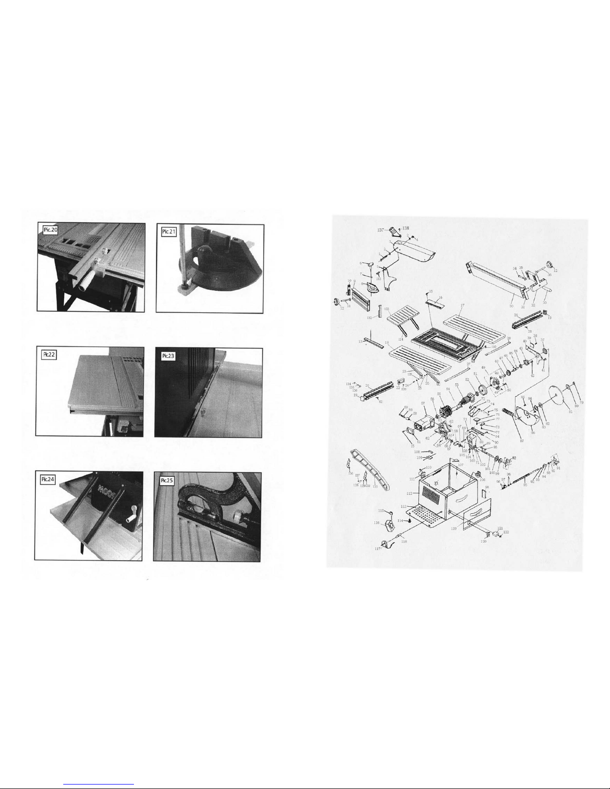
Mitre gauge adjustment. (Pic 21)
To check the accuracy of the mitre gauge, ensure that the pointer is set to 0° on the angle scale and perform a
cut. Check the angle of the cut, if it is not at 90° adjust the mitre gauge until a 90° cut is achieved. Check the
position of the pointer against the angle scale and if required adjust the position of the pointer to 0° by slackening the cross head pointer securing screw and set the pointer to zero on the angle scale and re-secure with the
cross head screw.
Fitting the table extensions. (Pic 22)
This table saw is supplied with left, right and rear table extensions to support larger pieces of material. These
extensions can be fitted individually or in any combination.
In order to fit the table extensions the table saw must be removed from the support legs and the bottom
cover plate removed.
The left and right table extensions are the same size but be aware that there are 2 holes on the shorter lengths
of the side extensions (to secure the rip fence slide profile) which should face the front of the saw. Secure the
table extension to the table saw using the bolts provided (Pic 23). Using two of the four short support struts and
attach one end to the outer edge of the extension and the other to the table saw (Pic 24), do not tighten the
bolts fully at this point as some adjustment may be required at a later date. Repeat this procedure for the remaining table extensions.
Note: The support struts for the rear table extension are longer.
When the table extensions are fitted as required check them for level using a spirit level and adjust as required.
(Pic 25)
No Volt release (NVR) ON/OFF Switch.
This machine is fitted with a "No Volt rele ase (NVR) Switch". In the event of a mains power failure or if the
mains plug is removed from the mains supply socket before the machine is switched off. The machine will not
re-start without warning when the mains supply is restored or the mains plug is re-connected to the mains supply, until the machine is switched ON at the ON/OFF switch fitted to the machine.
WARNING!
Before switching the table saw ON, make sure the blade guard is installed and operating correctly.
Check that the blade is set to 90
° and at its lowest position for the required job.
Ensure that the table is clear of any tools or other materials.
Ensure that all nuts, bolts and other fastenings are secure.
Starting and stopping. (Pic 26)
To start the machine, push the ON (1) switch (Pic 26).
To stop the machine, push the OFF (0) switch (Pic 26).
If the machine makes any unusual noise or vibrates excessively, STOP the machine immediately and investigate
the cause and rectify. If the cause cannot be identified DO NOT use the machine and contact your nearest service centre.
Controls and accessories.
The following is a brief description of each control and accessory and its typical uses.
The elevating handle. (Pic 27)
The elevating handle is used to raise and lower the blade. Turn the handle clockwise to lower the blade and
counter dock wise to raise the blade.
The tilting handle. (Pic 28)
The tilting handle is used to tilt the blade for bevel cutting. Turn the handle clockwise to tilt toward the left, and
counter clockwise to tilt toward the right.
Page 13

16
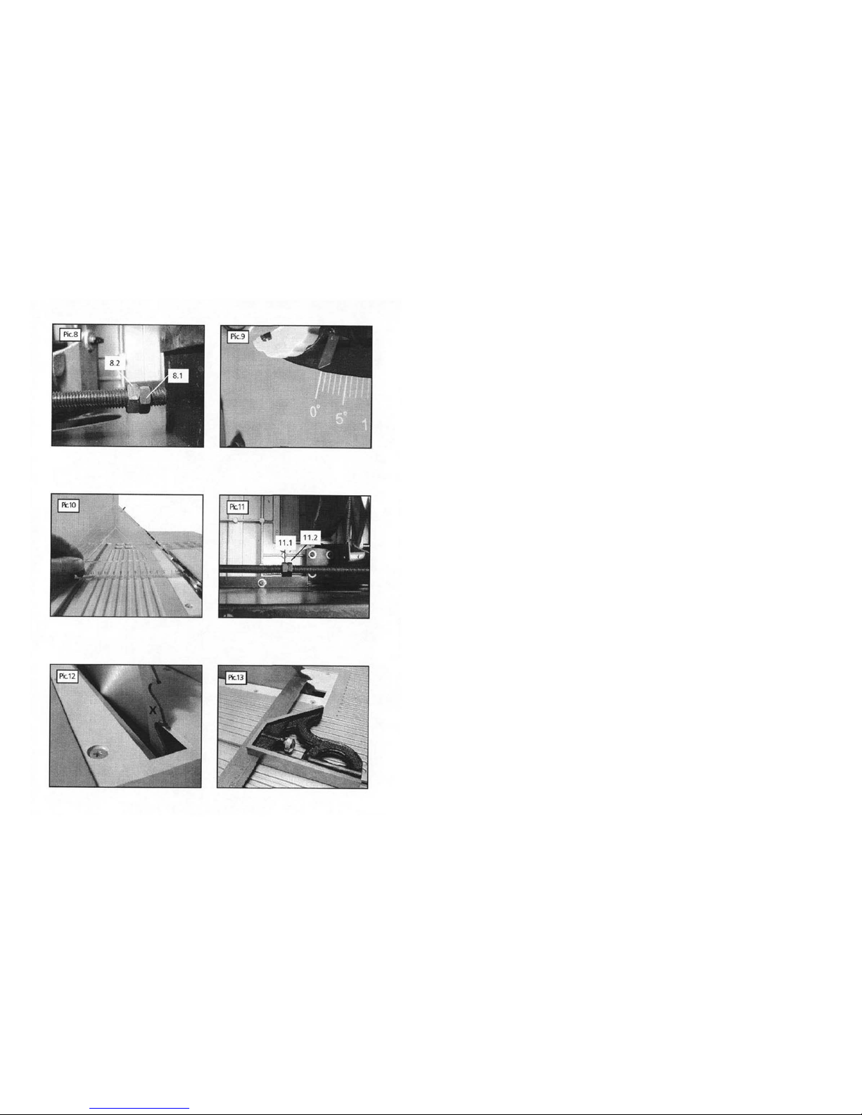
Setting the blade at 45° to the table. (Pics 7,10 and 11)
To check the angle, elevate the blade to its highest position and by using the tilt handle, tilt the
blade as far as it will go. Using a suitable set square, check the angle of the blade to the table is at
45
° (Pic l0). If adjustment is required, locate the set of adjustment and locking nuts on the tilt angle
operating screw furthest away from the motor (Pic 7) . Loosen the lock nut (Pic 11, 11.1) using two
wrenches. one for the lock nut and one for the adjustment nut (Pic 11, 11.2) and turn the adjustment nut until the blade is at 45° to the table. Then turn the lock nut (while holding the adjustment
nut in position) to fix the adjustment nut in place. Check the position of the angle indicator pointer
against the angle scale it should now align with the 45
° mark.
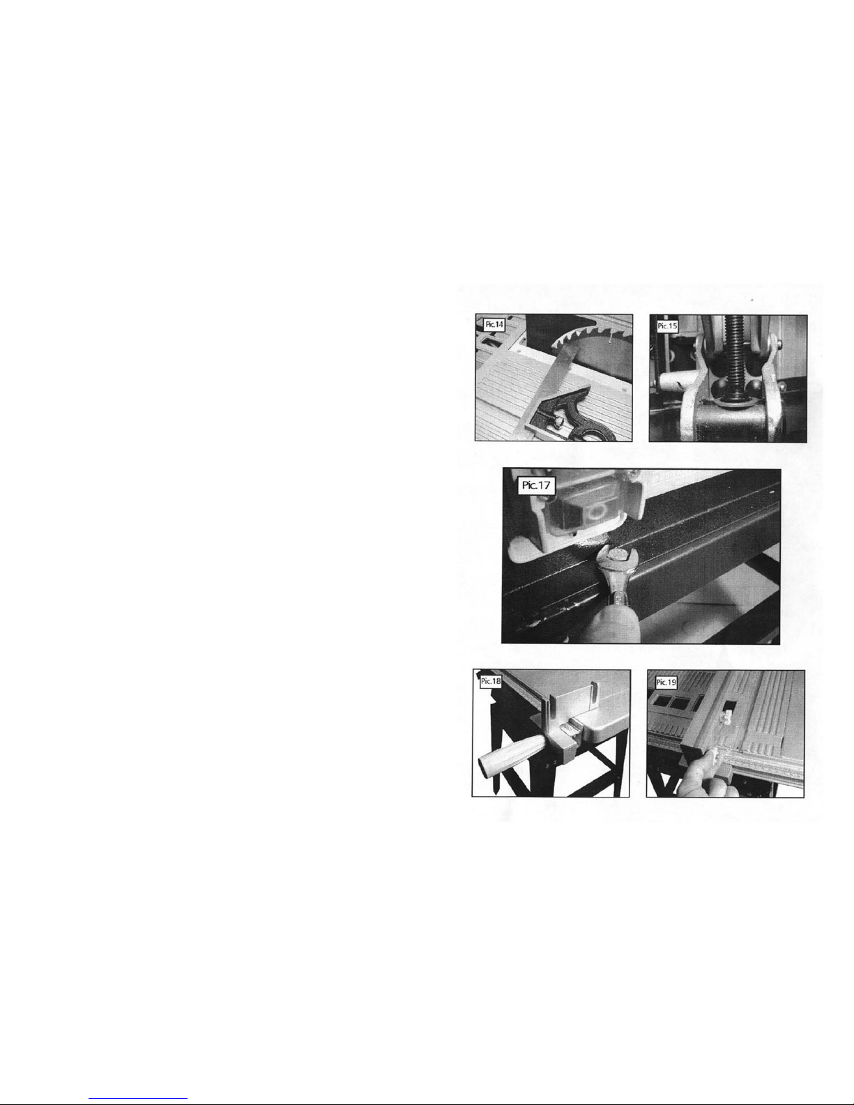
Checking the blade alignment. (Pics 12 to 15)
To check that the blade is set parallel to the two mitre gauge guide grooves machined in the table
(one on either side of the blade). Elevate the blade to its highest point and mark an “X” on one of
the teeth which is set (Bent) to the left and to the front of the blade slot in the table insert (Pic.l2).
Position the head
of
the combination square in the groove and adjust the blade of the square so that
it just contacts the tip of the marked tooth (Pic 13). Slide the combination square towards the rear of
the table and rotate the blade so that the marked tooth is to the rear of the slot in the table insert.
Check that the marked tooth again just contacts the blade of the combination square, to see if the
marked tooth again contacts the blade of the square (Pic l4).
If the marked tooth just contacts the combination square blade, when the marked tooth is positioned
at the front and rear of the blade slot in the table insert the saw blade is parallel to the mitre gauge
groove.
If the blade is not parallel tilt the blade to 45
° carefully turn the table saw over and remove the bot-
tom cover plate. Loosen the four bolts (Pic l5) and adjust the motor unit until the blade is set parallel
to the mitre gauge groove and then retighten the screws.
Mounting the table saw to the base. (Pic 17)
With an assistant lift the table saw onto the base. Care is required as the machine is not secured at
this stage and is liable to slip off the base possibly causing injury. Put the four washers onto the four
hexagonal bolts. While one person securely holds the table saw in place, locate the bolt though the
table saw base, passing through the hole in the base. Take the washer and hexagonal nut, secure
finger tight. Repeat this operation on all four comers. Using suitable ring spanners (not supplied)
tighten All four nuts.
Mounting the Rip Fence. (Pic 18 to 20)
Locate the rip fence mounting block (4) onto the slide profile located along the front edge of the
table saw, ensuring that the damping plate is located inside the groove in the slide profile (Pic 18).
Position the mounting block to the right of the blade and secure using the locking knob (Pic 18). Using the two coach bolts and knobs secure the rip fence onto the mounting block (Pic 19). The rip
fence can now be adjusted from left to right and from the front to back (Pic 20).
Fitting the mitre gauge. (Pic 21)
The mitre gauge simply locates in the location grooves one on either side of the blade (Pic 21). and
can be used for cutting at various angles.
13
Check Damaged Parts
Before using the power tool it should be carefully checked to determine that it will operate correctly
and perform its intended function. Check for the correct alignment of moving parts ensuring they do
not bind. Check for broken or missing parts and have them replaced or repaired at an authorised
service centre. If the power tool requires mounting make sure it is securely attached to a suitable
work bench. Check any other condition that may affect the operation of the power tool. A guard or
any other part of the power tool that is damaged should be correctly repaired or replaced by an
authorised service centre unless otherwise indicated in this instruction manual. Any switch that does
not operate correctly must be replaced by an authorised service centre. Do not use the power tool if
the ON/OFF switch does not turn the power tool ON and OFF.
Protect Furnishings
If using the power tool inside your house protect furnishings and floors with a suitable dust sheet.
Fire Precautions
When using certain power tools inside your house or workshop general fire precautions should be
observed. As a precaution it is recommended that an expert is consulted on obtaining and using a
suitable fire extinguisher.
Specific Safety Instructions -WARNING!
Some wood and wood type products, especially MDF (Medium Density Fibreboard), can produce dust
that can be hazardous to your health. We recommend the use of an approved face mask with replaceable filters when using this machine in addition to using the dust extraction facility.
Ensure that power tools are disconnected from the mains supply when not in use, before servicing,
lubricating or making adjustments and when changing accessories such as blades.
Do Not use blades made from High Speed Steel.
Do Not stop the blade by forcing the machine or by using sideways pressure. Do Not fit a grinding
or cutting disc to this machine. Always use the correct type of blade for the operation to be carried
out.
Do Not use blades that are bent or have missing teeth, This is highly dangerous and could result in a
serious accident causing injury to the operator, bystanders and damage to the machine.
Only use blades that are recommended by the supplier and that are in good condition.
Do Not use blades that are larger than specified.
Only use blades that are rated for the machine, The rotational speed shown on the blade should always be HIGHER than the rotational speed of the machine.
Ensure that the directional arrow marked on the blade corresponds with the rotational direction of
the motor, the teeth of the blade should always point downward as viewed from the front of the
saw.
Do Not lock the blade guard in the up position, Ensure that movable guards operate freely without
jamming.
Keep Guards in place and in good working order.
With the machine disconnected from the mains supply check the operation of the guard to ensure
that it operates correctly.
Always ensure that the blade is correctly, and securely fitted with the accessories supplied. Whenever replacing blades ensure that the recessed surface of the blade collar fits snugly against the surface of the blade. Ensure that the blade securing bolt is securely tightened using the wrenches provided. Do not over tighten. Use only blades that are recommended by the manufacturer.
Do not start the machine with the blade in contact with the work piece.
Page 14
14
Check the work piece for any protruding nails, screw heads or anything that could damage the blade.
Do not attempt to modify the machine or its accessories in any way.
Do not force the machine let the machine do the work this will reduce the wear on the machine and
blade and increase its efficiency and operating life.
Approved ear defenders should be worn when using this saw.
Do not cut timber greater than 7Smm, Metal, Stone, Rubber, Plastic or Bones Etc.
Do not fit any other tool or combination of blades.
Do not modify the machine or its guards/controls in any way.
Do not use with any covers/guards removed.
Always use the blade guard, riving knife and anti-kickback paws for every operation, including
through sawing. Through sawing operations are those in which the blade cuts completely through
the work piece when ripping or crosscutting.
Always hold the work firmly against the mitre gauge or fence.
Always use a push stick for ripping narrow stock. Refer to ripping applications in instruction manual.
Always use either the fence or the mitre gauge to position and guide the work.
Never stand or have any part of your body in line with the path of the saw blade.
Keep your hands out of the line of the saw blade.
Never reach behind or over the cutting tool for any reason, If off cuts of wood become jammed in
the machine, switch off and disconnect from supply before removal.
Feed the work piece into the blade against the direction of rotation only.
Never use the rip fence as a cutoff gauge when cross-cutting.
NEVER attempt to free a stalled saw blade without first turning the saw OFF.
Provide adequate support to the rear and sides of the saw table for wide or long work pieces.
Avoid kickback (work thrown back toward you) by keeping the blade sharp, keeping rip fence parallel
to the saw blade, keeping spreader and anti-kickback pawls (if fitted) and guard in place.
Do not release work before it is pushed all the way past the saw blade.
Do not rip work that is twisted or warped or does not have a straight edge to guide along the fence.
Avoid awkward operations and hand positions where a sudden slip could cause your hand to move
into the blade.
Never use solvents to clean plastic parts Solvents could possibly dissolve or otherwise damage the
material. Only
a
soft damp cloth should be used to clean plastic parts.
Use in a well ventilated area.
Remove sawdust frequently, Clean out sawdust from the interior of the sa w to prevent a potential
fire hazard. Saw dust is potentially hazardous to health. Always use a suitable dust collection system
and wear an approved face mask.
15
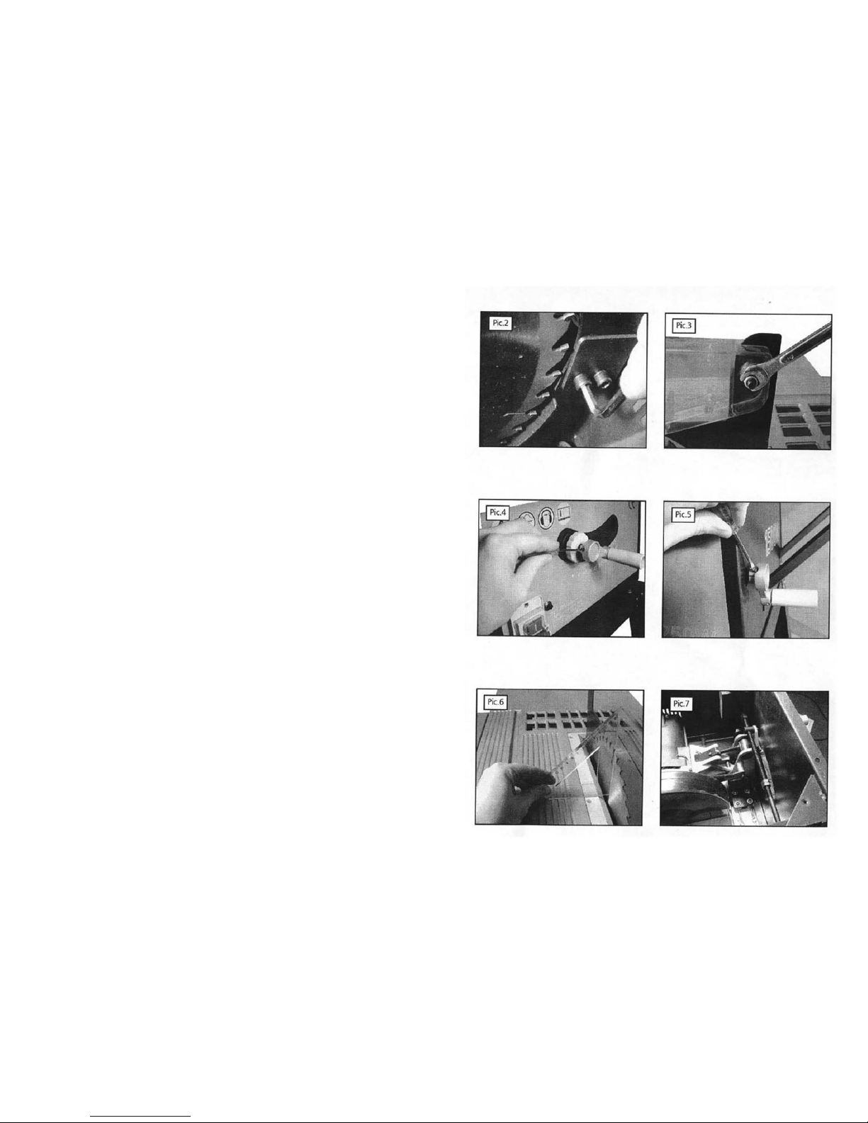
Fitting the Riving knife. (Pic 2)
To fit the riving knife, remove the table insert (16). With the table insert removed the two riving knife securing socket screws can be seen, Using a suitable sized hex key slacken the two socket screws, locate the riving knife and secure with the two socket screws. See (pic on page 9) for the correct setting of the riving
knife.
Fitting the blade guard. (Pic 3)
The blade guard (8) is attached to the riving knife. Remove the nylon nut and washer from the guard securing coach bolt and remove the bolt from the blade guard.
locate the blade guard over the riving knife, re-insert the guard securing coach bolt and refit the nylok nut
and washer. Check the operation of the blade guard, ensuring that it is correctly fitted and operates freely.
Mounting the elevating handle. (Pic 4)
The elevating screw is located at the front of the machine and has the locking knob (14) already fitted, locate
the elevating handle onto the end of the screw and secure by tightening the securing screw in the handle.
Mounting the tilting handle. (Pic 5)
The tilting screw is located at the side of the machine (13). locate the tilting handle onto the end of the screw
and secure by tightening the securing screw in the handle.
Adjusting the Blade. (Pics 6 & 7)
The blade has been set at the factory to be at an angle of 90° to the table. To check the angle elevate the
blade to its highest position and using an engineers square or a set square positioned against the table and
the blade, check that the angle is at 90° (Pic.6). If adjustment is required carefully turn the table saw over
and remove the bottom cover plate. Identify the tilt angle operating screw (Pic.7). The operating screw has
two sets of adjustment and locking nuts fitted. The set of nuts at the motor end of the screw are for setting
the blade at 90° to the table (0°) on the angle scale. The set at the other end of the screw, are for setting
the blade at 45 °to the table (45°) on the angle scale.
Setting the blade at 90° to the table. (Pic 7 to 9).
Loosen the lock nut (Pic 8,8.1l) using two wrenches, one for the lock nut and one for the adjustment nut (Pic
8,8.2) on the motor end of the operating screw (Pic 7) turn the adjustment nut until the blade is at 90° to
the table. Then turn the lock nut (while holding the adjustment nut in position) to fix the adjustment nut in
place. Check the position of the angle indicator pointer against the angle scale and adjust to 0° by loosening
the cross head screw and setting the pointer on 0° on the angle scale (Pic 9).
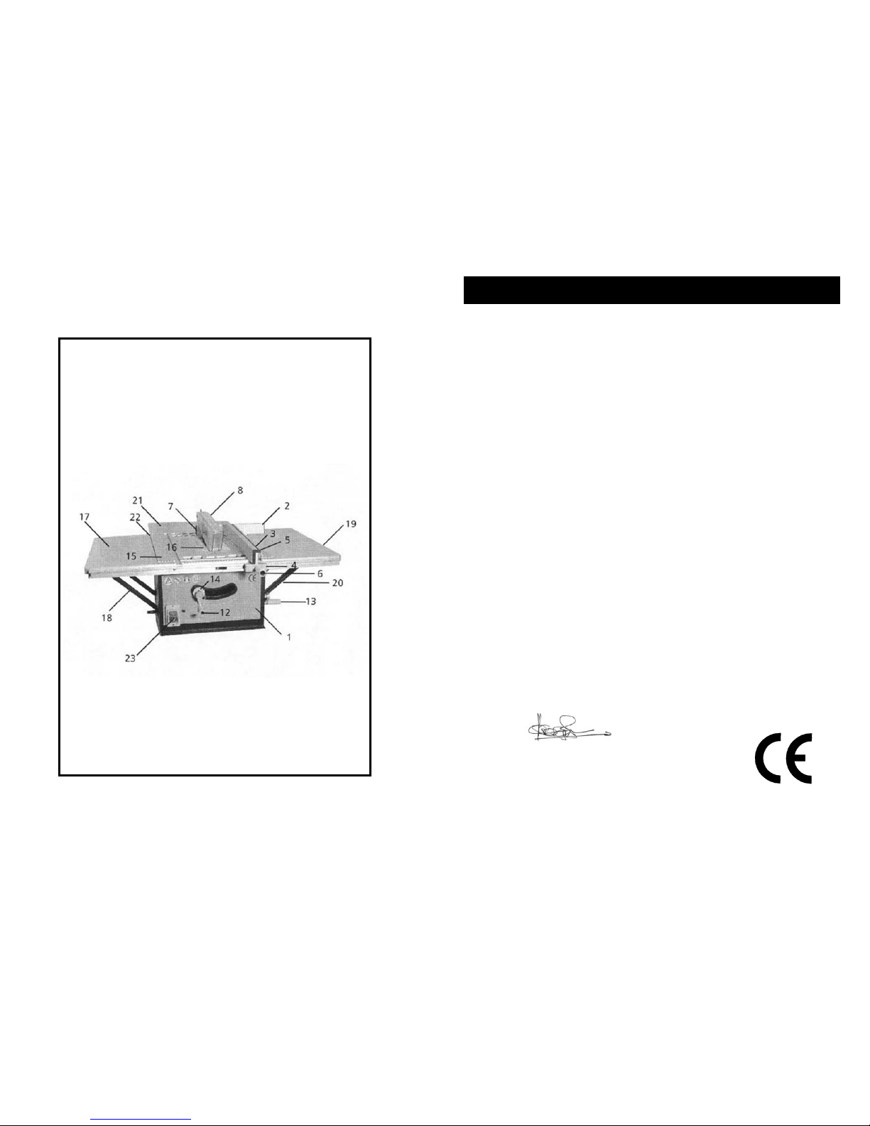
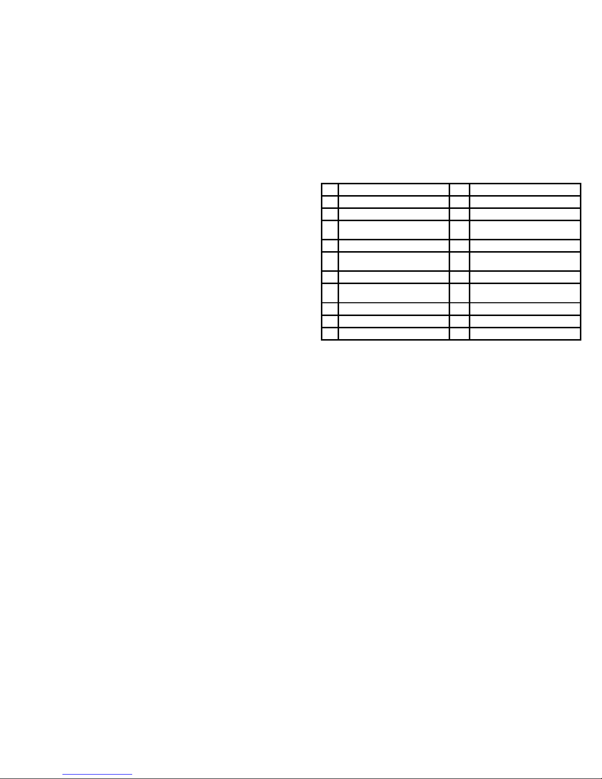
1 Table Saw 15 Table
2 Mitre gauge 16 Table insert
3 Rip fence 17 Table extension (left)
4 Rip fence mounting block 18 Table extension support struts
(left ) x 2
5 Rip fence securing knobs x 2 19 Table extension (Right)
6 Rip fence adjusting knob 20 Table extension support struts
(Right) x 2
7 Riving knife 21 Table extension (Rear)
8 Blade guard 22 Table extension support struts
(Rear) x 2
12 Table elevation handle 23
No Volt release (NVR) ON/OFF switch
13 Blade tilting handle 24 Fastenings
14 locking knob
 Loading...