

Sioux Tools 5062 User Manual

Model
5062
Form
Date
#
Z486
2-98/A
114"
Heavy
Duty
IMPORTANT
Read
these instructions carefully before installing, operating,,servicing or repairing this
tool. Keep these instructions in a safe accessible place.
II
SAFETY
Use
-
Safety Glasses
Use - Safety Gloves
Use
-
Safety
Use
-
Breathing
-
Ear Protectors
Use
-
Use accessories rated at least
-
Prolonged exposure to vibration may cause injury.
-
Read
all
be fully trained in
-
Do not exceed the maximum working air pressure.
-
Use personal protection equipment as recommended.
-
Use compressed air only at the recommended conditions.
-
If the tool appears to malfunction, remove from use
immediately and arrange for service and repair. If it is not
practical to remove tool from service, then shut off the air
supply to the tool and write or have written a warning
note and attach It to the tool.
-
If
tool is to be used with a balancer or other suspension
device, ensure that the tool is firmly attached to the
suspension/support device.
-
When operating the tool, always keep the body and
particularly the hands away from the working attachment
fixed to the tool.
-
The tool is not electrically insulated. Never use the tool if
there is any chance of coming into contact with live
electricity.
-
Always when using the tool, adopt a firm footing and/or
position and grip the tool sufficiently only to overcome
any reaction forces that may result from the tool doing
work. Do not overgrip.
-
Use only correct spare parts for maintenance and repair.
Do not improvise or make temporary repairs. Major
servicing and repairs should only be carried out by
persons trained to do so.
-
Do not lock, tape, wire, etc. the 'OnIOff valve in
On'position. The throttle triggertlever, etc. must always
be free to return to the
-
Always shut off the air supply to the tool and press the
'On/Offl valve to exhaust the air from the feed hose
before fitting, removing or adjusting the working attachment fitted to the tool.
-
Before using the tool, make sure that a shut off device
has been fitted to the supply line and
the ~osition is known and easilv acces-
siblh so that the air supply tothe tool
can be shut off in an emergency.
-
Check hose and fittings regularly for
wear.
-
Take care against entanglement of the
moving parts of the tool with clothing,
hair, ties, cleaning rags, rings,
jewelry, watches, bracelets, etc. This
could cause the body or parts of the
body to be drawn towards and in con-
tact
with
and could be very dangerous.
-
It Is expected that users will adopt safe
working practices and observe all
local, regional or country legal
MESSAGES
Personal Safety Equipment
YES
YES
Boots
Masks
instructions before using this tool.
its
use and aware of these
the moving parts of the tool
YES
YES
Safety
'Off'
rules
27,000
position when released.
A
WARNING
Always Read Instructions Before
0
"sing Power Tools
@
Always Wear Safety Goggles
@
Wear Hearing Protection
Avoid Prolonged Exposure
A
T o Vibration
when
RPM.
All
operators must
safety
rules.
7
Compressor Trap Water
Sufflcienl
with
To Maintain Recommended
Working
Each
Recommended
using
Capacity
Pressure
Tool Outlet
Air Supply
Page
No
-
-
-
-
-
-
-
-
-
-
At
Die
Grinder
Operator Instructions
Includes:
Safetv
ores seen
Work
Putting Into
Operating
a
5062
requirements when installing, using or maintaining the tool.
Take care that the exhaust air does not point towards any
other person or material or substance that could be
contaminated by oil droplets. When first lubricating a tool
or if the tool exhaust has a high oil content, do not allow
the exhaust air to come near very hot surfaces or flames.
Never lay the
stopped moving.
When the tool is not in use, shut off the air supply and
press throttle triggerllever to drain the supply line. If the
tool is not to be used for a period of time, first lubricate,
disconnect from air supply and store in a dry average room
temperature environment.
If the tool is passed from one user to a new or inexperienced user, make sure these instructions are available to
be passed with the tool.
Do
where fitted, i.e., wheel guards, safety trigger, speed
governors, etc.
Wherever possible, secure workpiece with clamps, a vise,
etc. to make it rigid so it does not move during the work
operation. Keep good balance at all times. Do not stretch
or overreach.
Try to match the tool to the work operation. Do not use a
tool that is too light or heavy tor the work operation. If in
doubt, seek advice.
In general terms, this tool is not suitable for underwater
use or use
manufacturer.
Try to make sure that the work area is clear to enable the
work task to be performed safely. If practical and
possible, try to clear unnecessary obstructions before
starting work.
Always use air hose and couplings with minimum working pressure ratings at least
working pressure rating of the tool.
Die
Grinder
tool
down until the working attachment has
not remove any manufacturer fitted safety devices
in
explosive environments - seek advice from
Take Air From Top
Rules
Use
Stations
Service
Dismantling and
1
112
times the maximum
Low Spot To
Assembly.
-
-
11
Drain Daily
Filter Lubricator
System
1
L
--
Figure
11
-I
1
Foreseen
This die grinder is primarily designed for use with
files and carbide
This tool should not be fitted with cut off wheels, saw blades, drill bits, etc. If there Is any doubt about the correct use of this product
contact your supplier for advice.
Also make sure that the shank size of the attachment to be driven matches with the collet size fined in the grinder and that the maximum
allowed running speed of the attachment exceeds that marked on the grinder.
There are special rulesgoverning the use of bonded abrasive mounted point grinding wheels
Use
Of
The
Tool
-
5062
bonded
buns
provided their speed rating matches the speed of the grinder.
abrasive mounted point grinding wheels. It may also be used with steel rotary
-
for details see section "Operating."
Work
Stations
The tool should only be used as a handheld, hand operated tool. It is always recommended that the tool is used when standing on a solid
floor. It can be used in other positions, but before any such use, the operator must be in a secure position having a firm grip and footing
and be aware of the extra safety precautions that must be observed when using grinding machines.
Putting Into Service
Air
Supply
Use a clean lubricated air supply that will give a measured air pressure at the tool of 90 PSiG (6.2 bar) when the tool is running with the
trigger~lever fully depressed. Use recommended hose size and length. It is recommended that the tool Is connected to the air supply as
shown In figure 1. Do not connect the tool to the air line system without Incorporating an easy to reach and operate air shut off valve.The
air supply should be lubricated. It is strongly recommended that an air filter, regulator, lubricator
this will supply clean, lubricated air at the correct pressure to the tool. Details of such equipment can be obtained from your supplier.
such equipment Is not used, then the tool should be lubricated by shutting off the air supply to the tool, depressurizing the line by pressing
the trigger on the tool. Disconnect the air line and pour into the hose adaptor a teaspoonful (5ml) of a suitable pneumatic motor lubricating
oil preferably incorporating a rust inhibitor. Reconnect tool to air supply and run tool slowly for a few seconds to allow air to circulate the
oil. If tool is used frequently, lubricate on daily basis and if tool starts to slow or lose power.
It is recommended that the air pressure at the tool while the tool is running is 90 PSU6.2 bar.
(FRL)
Is used as shown in Figure 1 as
Operating
Select a suitable mounted point that
that the diameter of the shank exactly matches the diameter of the collet mounted In the grinder.There are two standard sizes of collet
available for use with this grinder, i.e.,
1.
-
114" Dia.(0.250 ins)
2.
-
6mm Dia. (0.236 ins)
Always match correctly the shank size to the collet size. If uncertain, have parts measured by a competent person.
Push the shank
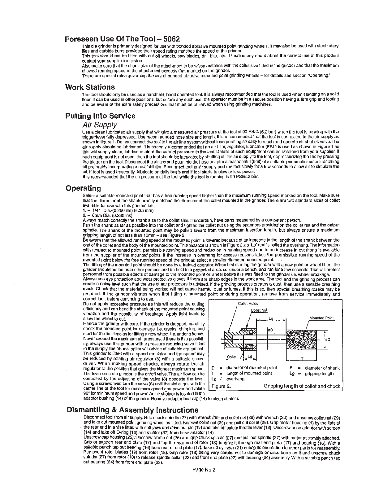
spindle. The shank of the mounted point may be pulled toward from the maximum insertion length, but always ensure a maximum
gripping length of not less than 10mm - see Figure 2.
Be aware that the allowed running speed of the mounted point is lowered because of an Increase In the iengthof the shank between the
end of the collet and the body of the mounted point.This distance is shown inFigure 2.asULo'and is called the overhang. The information
with respect to mounted polnt, permissible running speed and reduction in running speed due to an increase in overhang is available
from the supplier of the mounted points. It the Increase in overhang for access reasons takes the permissible running speed of the
mounted point below the free running speed of the grinder, select a smaller diameter mounted point.
The fitting of the mounted point should be done by a trained operator. When first starting the grinder with a new point or wheel fitted, the
grinder should not be near other persons and be held in a protected area. 1.e. under a bench, and run fora few seconds.This will protect
personnel from possible effects of damage to the mounted polnt or wheel before it is was fitted to the grinder i.e. wheel breakage.
Always use
create
mask. Check that the material being worked will not cause harmful dust or fumes. If this is so, then special breathing masks may be
required. If the grinder vibrates when first fitting a mounted point or during operation, remove from service immediately and
correct fault before continuing to use.
Do not apply excessive pressure as this will reduce the cutting
efficiency and can bend the shank of the mounted point causing
vibration and the possibility of breakage. Apply light loads to
allow the wheel to cut.
Handle the grinder with care. If the grinder is dropped, carefully
check the mounted polnt for damage, 1.0. cracks, chipping,
start for the first time as for fitting a new wheel, i.e. under a bench.
Never exceed the maximum air pressure. If there is this possibiiity, always use this grinder with
in the supply line.Your supplier will advise of suitable equipment.
This grinder Is lilted with
be reduced by rotating alr regulator (8) with a suitable screwdriver. When making speed checks, always rotate the air
regulator to the position that gives the highest maximum speed.
The lever on a die grinder is the ontoff valve,Thg air flow
controlled by the adiustino of the valve
Using a screwdriver, turn the valve (8) untilthe slot aligns with the
center
90'
for minimum speed and power. An air strainer is located in the
adaptor bushing (14) of the grinder. Remove adaptor bushing
as
eye
protection and wear protective gloves
a
noise level such that the use of ear protectors is advised. If the grinding process creates a dust, then use a suitable breathing
line
of the tool tor maxlmum speed gnd power and roiate
(6.35
far
as possible into the coliet and tighten the collet nut using the spanners provided on the collet nut and the output
a
has
a free running speed higher than the maximum running speed marked on the tool. Make sure
mm)
If
there are sharp edges in the work area. The tool and the grinding process can
and
a
pressure reducing
speed regulator and the speed may
(81
valve
ODDOS~~~
can
the lever.
fitted
be
(14)
D
=
diarderof ~'~~ounted point
T
=
length of mounted point Lg = gripping length
Lo = overhand
1
Figure
2'
to clean strainer.
Collet
Holder
Gripping length
S
=
of
If
diameter of shank
collet
and
chuck
Dismantling & Assembly
Disconnect tool from airsupply. Grip chuck spindle (27) with wrench
and take out mounted point grinding wheel as fitted. Remove collet nut
the rear end In a vise fitted with soft jaws and drive out pin (13) and take off safety throttle lever (12). Unscrew hose adaptorwith screen
(14)
and
take
Unscrew cap housing (26). Unscrew clamp nut
Grip or support rear end plate (17) and tap the rear end of rotor (18) to drive it through rear end plate (17) and bearing (16). With a
suitable punch lap out bearing
Remove 4 rotor blades
spindle (27) from mtor (18) to release spindle collar (23) and fmnf end plate
out bearing (24) from front end plate (22).
off O-ring (15) and muffler (37) from hose adaptor
(19)
Instructions
(30)
and collet nut (29) with wrench
(29)
and pull out collet (28). Grip motor housing
Page
(14).
very
careful not to damage or raise burrs on it and unscrew chuck
No
2
(25)
and grip chuck spindle (27) and pull out spindle (27) with motor assembly attached.
(16)
from rear of end plate (17).Take off cylinder (21) noting
from rotor
(18).
Grip mtor (18) being
(30)
and unscrew collet nut (29)
US
orientation to other parts for reassembly.
(22)
with bearing (24) assembly. With a suitable punch tap
(1)
by the flats at
 Loading...