

Page 1
INSTRUCTIONS AND PARTS LIST
FOR 1446ES AIR SHEAR
(SERIAL “B”)
AIR SUPPLY
The efficiency and life of this tool depends on the proper
supply of clean, dry, lubricated air at about 90 lbs. P.S.I.,
although higher or lower pressures may be used. The use
of an air line filter, pressure regulator and lubricator is
recommended.
Before connecting the tool, blow the air line to remove
water and dirt which may have accumulated. This is
especially important for a new line or when the line has not
been used for some time.
HOSE AND HOSE CONNECTION
The air supply hose is 3/8" I.D. If extension hose is necessary, use 1/2" hose, with couplings not less than 3/8" I.D.
LUBRICATION
An oil supply to the air motor is important. SIOUX air line
lubricators are recommended. Adjust to deliver 2 drops of
SIOUX Air Motor Oil No. 288 per minute. When air line
lubricator is not used squirt several drops of oil into the air
inlet before using. Shear head must be lubricated after
every 40 hrs. of operation, with SIOUX Grease No. 289A.
SAFETY
1. Keep work area clean.
2. Do not force tool.
3. Secure work where possible- use clamps or vise.
4. Keep tools sharp and in good shape.
5. Disconnect tools when not in use.
6. The use of accessories not provided or specified may
be hazardous.
7. Use goggles or safety glasses.
WARNING
Designed to cut only up to 16 gauge steel, plastic and
associated materials up to 3/32" thick. Failure to grease
could void warranty. Sioux Tools cannot assume responsibility for damage to or malfunction of a shear head used in
combination with any drill other than those regularly supplied by Sioux Tools.
SHEAR HEAD MAINTENANCE INSTRUCTIONS
ADJUSTMENT
To adjust the curl of waste material, the left side knife
54500 has elongated holes. Adjustment may be necessary
after changing blades or material being cut. Loosen cap
screws 07102 and tap side knife 54500 either forward or
backward so that curl of waste does not hit shear housing
12598 of work material while cutting.
DISASSEMBLY
To remove 53609 shear head from power unit and dismantle:
1. Loosen both rear cap screws 07102 three complete
turns.
2. Remove shear head assembly 53609 from motor by
Form Z545A
Date 2004January22/A
Page 1 of 4
pulling head firmly forward. Slight twisting action may be
required.
3. Remove three cap screws 07102 completely from shear
housing 12598. Be careful not to lose rear spacer bushing 54502 when removing rear cap screw.
4. Remove center blade 54499 from shear housing 12598
by tapping blade gently rearward. Be careful not to lose
spacer bushing 54502 from hole in center blade.
5. Side Knives 54500 and 54501 will now drop out of shear
housing.
ASSEMBLY
To assemble 53609 shear head and adapt to power unit:
1. Place the left side knife 54500 into position in the shear
housing.
2. Insert center cap screw 07102 through housing and blade
just far enough to slip spacer bushing 54502 over cap
screw.
3. Place right side knife 54501 into position and push center cap screw through right side knife. Start cap screw
into insert just enough to hold blades in place.
DO NOT TIGHTEN.
4. Insert spacer bushing 54502 into hole in center blade
54499 and lubricate with a good grade of bearing grease.
5. Install center blade 54499 into shear housing 12598 by
tapping blade gently forward using a drift to line up hole
in center blade with forward holes in housing.
6. Insert and tighten forward cap screw 07102 making sure
spacer bushing 54502 in center blade stays in position.
Apply good grade of bearing grease to clevis in center
blade. WHEN SHEAR HEAD IS PROPERLY AS-
SEMBLED THE CENTER BLADE WILL PIVOT FREELY
IN HEAD.
7. Insert rear cap screw 07102 into shear housing 12598
but do not completely tighten.
To install shear head assembly 53609 onto power unit:
1. Make sure rear cap screw and center cap screw 07102
are loosened three complete turns.
2. Place shear head onto unit and tighten cap screws 07102
snugly to lock head assembly in place. It may be necessary to gently tap the shear head assembly into place if
it does not readily slip onto the power unit.
Printed In U.S.A.
1
Page 2
2
Page 3

INSTRUCTIONS AND PARTS LIST FOR 1446ES AIR SHEAR
(SERIAL “B”)
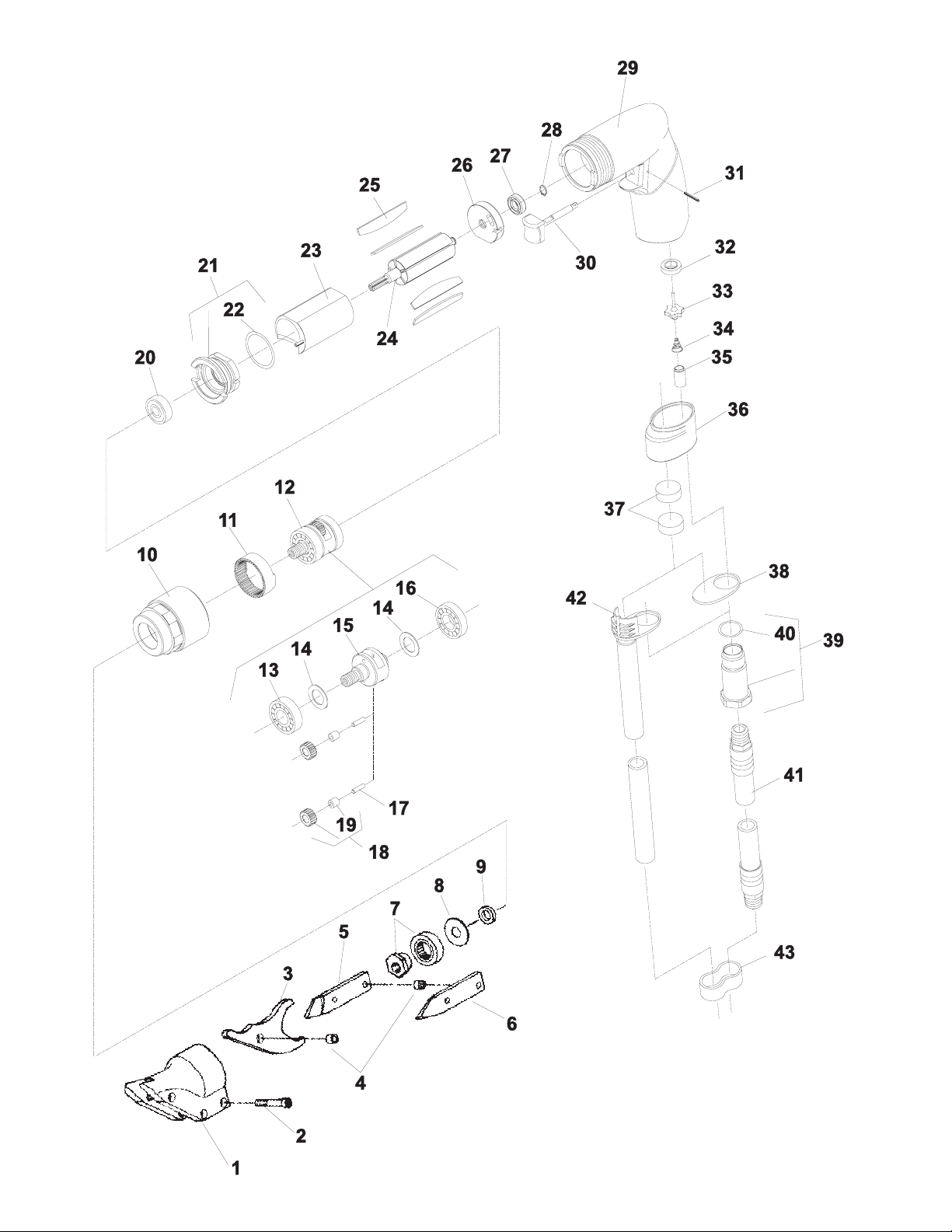
Fig. Part
No. No. Description
1. 12598 Housing-Shear
2. 07102 Screw-Socket Head Cap (3)*
3. 54499 Blade-Center
4. 54502 Bushing-Spacer (2)*
5. 54501 Knife-Side (Right)
6. 54500 Knife-Side (Left)
7. 53614 Ass’y-Eccentric
8. 35308 Washer
9. 44122 Spacer (For 1/4" Chucks)
10. 68798 Case-Gear
11. 67858 Gear-Ring
12. 67893 Ass’y-Planetary Reduction (Includes Fig. 13-19)
13. 10228 Bearing-Ball
14. 25439 Washer (2)*
15. 67869 Carrier-Gear
16. 10203 Bearing-Ball
17. 67857 Pin (2)*
18. 67944 Ass’y-Gear & Bearing (2)*
19. 10080 Bearing-Needle (2)*
20. 10220 Bearing-Ball
21. 13550 End Plate-Front (Includes Fig. 22)
22. 14342 Ring-”O”
23. 64057 Cylinder
24. 67855 Rotor-6 Tooth
25. 63192 Ass’y-Rotor Vane (Set of 5)
26. 67803 End Plate-Rear
27. 10253 Bearing-Ball (Seal side out)
28. 21491 Ring-Retainer
29. 67797 Housing (Includes Figs. 30, 31)
30. 67805 Trigger
31. 30610 Roll Pin
32. 67798 Seat-Valve
33. 67804 Valve
34. 68791 Spring
35. 68792 Trigger Spring Spacer
36. 67800B Muffler
37. 67807 Silencer-Pad (3)*
38. 67801A Cap-Muffler
39. 67819 Adapter-Inlet (Includes Fig. 40)
40. 14378 Ring-”O”
41. 1376 Ass’y-Leader Hose
42. 67128 Hose-Exhaust
43. 40153 Clip-Hose (3)* Remote Exhaust
Complete Assembly
67126 Ass’y-Housing (Includes Fig. 29-30, 32-40)
67827 Ass’y-Motor (6 Tooth)(Includes Fig. 20-28)
*Order Quantity As Needed
FURNISH CATALOG, SERIAL, AND MODEL NUMBER
WHEN ORDERING PARTS
3
Page 4
Some dust created by power sanding, sawing, grinding, drilling, and other construc-
tion activities contains chemicals known to cause cancer, birth defects or other
reproductive harm.
El polvo generado al lijar, aserrar, afilar, taladrar y realizar otras tareas de
construcción contiene sustancias químicas que podrían causar cáncer,
malformaciones congénitas y otras alteraciones del aparato reproductor.
Printed In U.S.A.
4
 Loading...