

Page 1

www.sintroncorp.com
Address: 2880 Zanker Rd, Suite 207, San Jose CA 95134 USA TEL: 408-800-1413 / FAX: 510-952-8282 / [email protected]
VMT-825
User’s Manual
Edition: V 2.20
Model: VMT-825
Renew time:2011-07-20
Page 2

www.sintroncorp.com
Address: 2880 Zanker Rd, Suite 207, San Jose CA 95134 USA TEL: 408-800-1413 / FAX: 510-952-8282 / [email protected]
Copyright
The documentation and the software included with this product are copyrighted
2011 by Sintron Technology Corp. All rights are reserved.
Sintron reserves the right to make improvements in the products described in this
manual at any time without notice. No part of this manual may be reproduced,
copied, translated or transmitted in any form or by any means without the prior
written permission of Sintron Information provided in this manual is intended to be
accurate and reliable.
However, Sintron assumes no responsibility for its use, nor for any infringements
of the rights of third parties, which may result from its use.
Page 3

www.sintroncorp.com
Address: 2880 Zanker Rd, Suite 207, San Jose CA 95134 USA TEL: 408-800-1413 / FAX: 510-952-8282 / [email protected]
FCC Class B
Note: This equipment has been tested and found to comply with the limits for a
Class B digital device, pursuant to part 15 of the FCC Rules. These limits are
designed to provide reasonable protection against harmful interference in a
residential installation. This equipment generates uses and can radiate radio
frequency energy and, if not installed and used in accordance with the instructions,
may cause harmful interference to radio communications. However, there is no
guarantee that interference will not occur in a particular installation. If this
equipment does cause harmful interference to radio or television reception, which
can be determined by turning the equipment off and on, the user is encouraged to
try to correct the interference by one or more of the following measures:
. Reorient or relocate the receiving antenna.
. Increase the separation between the equipment and receiver.
. Connect the equipment into an outlet on a circuit different from that to which the
receiver is connected. Consult the dealer or an experienced radio/TV technician for
help.
Page 4

www.sintroncorp.com
Address: 2880 Zanker Rd, Suite 207, San Jose CA 95134 USA TEL: 408-800-1413 / FAX: 510-952-8282 / [email protected]
Technical Support and Assistance
1. Visit the Sintron web site at www.sintroncorp.com where you can find the
latest information about the product.
2. Contact your distributor, sales representative, or Sintron’s customer service
center for technical support if you need additional assistance. Please have the
following information ready before you call:
. Product name and serial number
. Description of your peripheral attachments
. Description of your software (operating system, version, application software,
etc)
. A complete description of the problem
. The exact wording of any error messages
Page 5

www.sintroncorp.com
Address: 2880 Zanker Rd, Suite 207, San Jose CA 95134 USA TEL: 408-800-1413 / FAX: 510-952-8282 / [email protected]
Safety Instructions
1. Read these safety instructions carefully.
2. Keep this User Manual for later reference.
3. Disconnect this equipment from any AC outlet before cleaning. Use a damp
cloth. Do not use liquid or spray detergents for cleaning.
4. For plug-in equipment, the power outlet socket must be located near the
equipment and must be easily accessible.
5. Keep this equipment away from humidity.
6. Put this equipment on a reliable surface during installation. Dropping it or letting
it fall may cause damage.
7. The openings on the enclosure are for air convection. Protect the equipment
from overheating. DO NOT COVER THE OPENINGS.
8. Make sure the voltage of the power source is correct before connecting the
equipment to the power outlet.
9. Position the power cord so that people cannot step on it. Do not place anything
over the power cord.
10. All cautions and warnings on the equipment should be noted.
11. If the equipment is not used for a long time, disconnect it from the power
source to avoid damage by transient overvoltage.
12. Never pour any liquid into an opening. This may cause fire or electrical shock.
13. Never open the equipment. For safety reasons, the equipment should be opened
only by qualified service personnel.
The sound pressure level at the operator’s position according to IEC 704-1:1982 is
no more than 70 dB (A).
DISCLAIMER: This set of instructions is given according to IEC 704-1. Sintron
disclaims all responsibility for the accuracy of any statements contained herein.
Page 6

www.sintroncorp.com
Address: 2880 Zanker Rd, Suite 207, San Jose CA 95134 USA TEL: 408-800-1413 / FAX: 510-952-8282 / [email protected]
Contents
Chapter 1 General Information ............................................................................. 9
1.1 Introduction ............................................................................................................................................. 9
1.2 General Specifications ............................................................................................................................. 9
1.3 LCD Specifications ................................................................................................................................. 11
1.4 Dimensions ............................................................................................................................................. 12
Chapter 2 System Setup ........................................................................................ 13
2.1 A Quick Tour of the Vehicle Mounted Computer .............................................................................. 13
2.2 Installation Procedures ......................................................................................................................... 16
2.2.1 Connecting the Power Cord ....................................................................................................... 16
2.2.2 Connecting the Keyboard or Mouse ......................................................................................... 16
2.2.3 Switching On the Power ............................................................................................................. 16
2.3 Running the BIOS Setup Program ....................................................................................................... 17
2.4 Installing System Software .................................................................................................................... 17
2.5 Installing the Drivers ............................................................................................................................. 18
Chapter 3 Hardware and Peripheral Installation .............................................. 19
3.1 Overview of Hardware Installation and Upgrading ........................................................................... 19
3.2 Installing the Storage Device ................................................................................................................ 19
3.2.1 Installing the 2.5" hard disk drive (HDD) ................................................................................ 19
3.2.2 Installing the Compact Flash Card (CFC) ............................................................................... 21
3.3 Placing the Rubber Seal ........................................................................................................................ 22
3.4 Installing the Optional Accessories ...................................................................................................... 22
3.4.1 Installing the .Universal Arm. ................................................................................................... 23
3.4.2 Installing RAM-MOUNT .kits. .................................................................................................. 23
3.4.3 Installing the MiniPCI WLAN module ..................................................................................... 24
3.4.4 Installing GPS and GSM/GPRS modules ................................................................................. 25
Chapter 4 Jumper Settings and Connectors ....................................................... 28
4.1 Setting Jumpers ..................................................................................................................................... 28
4.1.1 Jumpers and switches ................................................................................................................. 28
4.1.2 Locating jumpers and switches.................................................................................................. 29
4.1.3 Connectors on the motherboard ................................................................................................ 30
4.1.4 Locating connectors on the motherboard ................................................................................. 31
4.1.5 Jumpers and switches on power board ..................................................................................... 32
4.1.6 Locating jumpers, connectors and LEDs on power board ...................................................... 33
4.2 CPU Installation..................................................................................................................................... 34
4.3 Jumper Settings on Mother-Board ...................................................................................................... 34
4.3.1 LCD panel power setting (JP1) .................................................................................................. 34
Page 7

www.sintroncorp.com
Address: 2880 Zanker Rd, Suite 207, San Jose CA 95134 USA TEL: 408-800-1413 / FAX: 510-952-8282 / [email protected]
4.3.2 Panel Type Setting (JP5) ............................................................................................................ 34
4.3.3 CMOS clear for external RTC (JP2) ........................................................................................ 35
4.4 COM-port Interface .............................................................................................................................. 36
4.4.1 COM port Pin 9 power output setting (JP3) ............................................................................ 37
4.4.2 COM port Pin 9 power output value setting (JP4) .................................................................. 37
4.5 Jumper Setting on Power-Board .......................................................................................................... 38
4.5.1 Low battery monitor and shut down (CN2) ............................................................................. 38
4.5.2 Power off delay setting connector (CN7) .................................................................................. 38
4.5.3 Ignition input switch jumper (CN8) .......................................................................................... 39
Chapter 5 Intel Chipset ......................................................................................... 40
5.1 Introduction ........................................................................................................................................... 40
5.1.1 Installation for Windows 98 ....................................................................................................... 40
5.1.2 Installation for Windows 2000 / XP .......................................................................................... 40
5.2 Further Information .............................................................................................................................. 41
Chapter 6 Graphic Chipset .................................................................................. 42
6.1 Introduction ........................................................................................................................................... 42
6.1.1 Installation for Windows 2000 / XP .......................................................................................... 42
6.2 Further Information .............................................................................................................................. 42
Chapter 7 Audio .................................................................................................... 43
7.1 Introduction ........................................................................................................................................... 43
7.2 Installation of Audio Driver .................................................................................................................. 43
Chapter 8 USB 2.0 ................................................................................................. 44
8.1 Introduction ........................................................................................................................................... 44
8.2 Installation of USB Driver .................................................................................................................... 44
Chapter 9 Touchscreen ......................................................................................... 45
9.1 Introduction ........................................................................................................................................... 45
9.1.1 General information ................................................................................................................... 45
9.1.2 General specifications ................................................................................................................. 45
9.2 Installation of Touchscreen Driver ...................................................................................................... 46
9.2.1 Windows 98-Me-2000-2003 driver ............................................................................................ 46
9.2.2 Windows XP driver .................................................................................................................... 47
9.3 Further Information .............................................................................................................................. 47
Appendix A Pin Assignments .................................................................................. 48
A.1 Inverter power connector (CN2) ......................................................................................................... 48
A.2 Internal speaker connector (CN21) ..................................................................................................... 48
A.3 IDE hard disk drive connector (CN5) ................................................................................................. 49
A.4 LVDS connector (CN1) ........................................................................................................................ 50
A.5 COM 1, 2 ................................................................................................................................................ 51
Page 8

www.sintroncorp.com
Address: 2880 Zanker Rd, Suite 207, San Jose CA 95134 USA TEL: 408-800-1413 / FAX: 510-952-8282 / [email protected]
A.6 COM 3, 4 ................................................................................................................................................ 52
A.7 COM 3, 4 internal connector (CN18, 16) ............................................................................................ 53
A.8 Internal USB port ................................................................................................................................. 54
A.9 Reserved Parallel port connector (CN11) ........................................................................................... 55
A.10 Power Inlet........................................................................................................................................... 56
Appendix B Key Features Setting in BIOS ............................................................ 57
B.1 Panel Type Setting in BIOS .................................................................................................................. 57
B.2 Power Fail Function Setting in BIOS .................................................................................................. 59
Page 9

www.sintroncorp.com
Address: 2880 Zanker Rd, Suite 207, San Jose CA 95134 USA TEL: 408-800-1413 / FAX: 510-952-8282 / [email protected]
Chapter 1 General Information
1.1 Introduction
VMT-825 is fanless and is supplied with either Intel ULV Celeron® M or LV CPU
for higher reliability and performance. The ruggedized aluminum enclosure is built
without ventilation holes and makes VMT-825 waterproof and dust proof.
A power source with wide input range suits vehicles such as forklifts and trucks,
which typically operate with 12 V, 24 V, or 48 V DC power. When equipped
with an adapter, it can operate with AC power.
VMT-825 provides 10/100Base-T Ethernet, and expansion options for wireless
transmissions such as 802.11b/g, GPS, GSM and GPRS, etc.
Embedded OS support (WinCE.NET, WinXP Embedded), using OS images can
greatly shorten system development and trouble-shooting.
1.2 General Specifications
General
• Dimensions (W x H x D): 310 x 255 x 90 mm ;
• Weight: 4.8 kg
• Power supply:
Minimum Input voltage: 6 Vdc. (Supports cold crank Ignition)
Maximum Input voltage: 58 Vdc.
Minimum Startup voltage: 9 Vdc.
Low battery shut-down protection threshold (option): 11 Vdc.
(When the battery voltage level drops below 11V in the vehicle for more
than 30 seconds, the system will start to shut down in order to prevent
battery being drained and will automatically re-activate only when the
voltage is greater than 11V.)
Power Off delay (option):30 seconds.
(When system power is con-trolled by ignition key, then whenever the key
is turned off, the computer system will power-off completely after 30
Page 10

www.sintroncorp.com
Address: 2880 Zanker Rd, Suite 207, San Jose CA 95134 USA TEL: 408-800-1413 / FAX: 510-952-8282 / [email protected]
seconds while the OS terminates.)
* For more detail of optional function please refer to Chapter 4, Section 4.5 of this manual.
• Disk drive housing: Space for one 2.5" HDD or Compact Flash Card
• Front panel and back cover: IP65 Sealed; NEMA4 compliant
• Enclosure: Ruggedized aluminum without ventilation holes
Standard PC functions
• CPU: Intel ULV Celeron M 600MHz with 512 KB L2 cache /LV Pentium M
1.1GHz with 1MB L2 cache
• BIOS: Award 4 MB Flash BIOS, ACPI 2.0 Compliant
• System chipset: Intel 855GME and ICH4-M
• Front side bus: 400 MHz
• System memory: Two 184-pin DIMM sockets, accepting up to 2 GB
DDR 333 SDRAM
• IDE interface: Supports one connector. One channel supports two IDE devices.
Each IDE supports PIO modes 0 ~ 4, DMA mode 0 ~ 2, and
Ultra DMA 33/66/ 100 simultaneously
• Keyboard/mouse connector: Supports 1 standard PS/2 Keyboard and a PS/2
Mouse
• Serial ports: Four serial ports with two RS-232/422/485 ports (COM1, COM 2;
adjust by BIOS), and two RS-232 port (COM3, COM 4). All
ports are compatible with 16C550. UARTs and +5V/+12V power
supply are selectable
• Universal serial bus (USB) port: Supports up to two EHCI USB2.0
• Mini PCI bus expansion slot: Accepts one type III A/B mini PCI bus card
• Solid state disk: Supports one 50-pin socket for Compact Flash type I/II (True
IDE mode)
• Watchdog timer: 256-level interval from 1 to 255 seconds. Jumper less
selection and software can be enabled / disabled.
• Battery: 3.0 V @ 195 mA lithium battery
• Power management: Supports power saving modes including Normal/
Standby/Suspend modes. APM 1.2 compliant
Page 11

www.sintroncorp.com
Address: 2880 Zanker Rd, Suite 207, San Jose CA 95134 USA TEL: 408-800-1413 / FAX: 510-952-8282 / [email protected]
Environment
• Operating Temperature:
• VMT-825: 0 ~ 40° C (32 ~ 104° F) for HDD;
-30 ~ 60° C (-22 ~ 140° F) for CFC *
* It is also suitable for industrial grade, wide-temperature range HDDs
• Relative Humidity: 10 ~ 95% @ 40° C (non-condensing)
• Shock: 30 G peak acceleration (11 msec duration)
• Safety: UL, CUL, CE; CCC, CB
• Vibration: 5 ~ 500 Hz 1 G RMS Random vibration (operating with HDD); 5 ~
500 Hz 3G RMS random vibration (operating with CF card)
1.3 LCD Specifications
Display type: 12.1" TFT LCD
Max. resolution: 1024 x 768
Colors: 262K
Dot size (mm): 0.264*0.264
Luminance: 400 cd/m2
Viewing Angle (H/V): 160/160
LCD MTBF: 50000 hours
Backlight lifetime: 50000 hours
Note: The color LCD display installed in the Vehicle Mounted Computer is
high-quality and reliable. However, it may contain a few defective pixels
which do not always illuminate. With current technology, it is impossible
to completely eliminate defective pixels. Sintron is actively working to
improve this technology.
Page 12

www.sintroncorp.com
Address: 2880 Zanker Rd, Suite 207, San Jose CA 95134 USA TEL: 408-800-1413 / FAX: 510-952-8282 / [email protected]
1.4 Dimensions
All dimensions are in millimeters.
Page 13
www.sintroncorp.com
Address: 2880 Zanker Rd, Suite 207, San Jose CA 95134 USA TEL: 408-800-1413 / FAX: 510-952-8282 / [email protected]
Chapter 2 System Setup
2.1 A Quick Tour of the Vehicle Mounted Computer
Before starting to set up the Vehicle Mounted Computer, take a moment to become
familiar with the locations and purposes of the controls, drives, connectors and
ports, which are illustrated in the figures below.
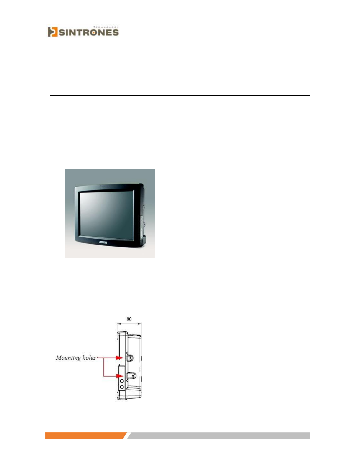
When you place the Vehicle Mounted Computer upright on the desktop,
its front panel appears as shown in Figure 2.1
Figure 2.1
Mounting holes are located on the right side of the Vehicle Mounted Computer, as
shown in Figure 2.2
Figure 2.2
Page 14
www.sintroncorp.com
Address: 2880 Zanker Rd, Suite 207, San Jose CA 95134 USA TEL: 408-800-1413 / FAX: 510-952-8282 / [email protected]
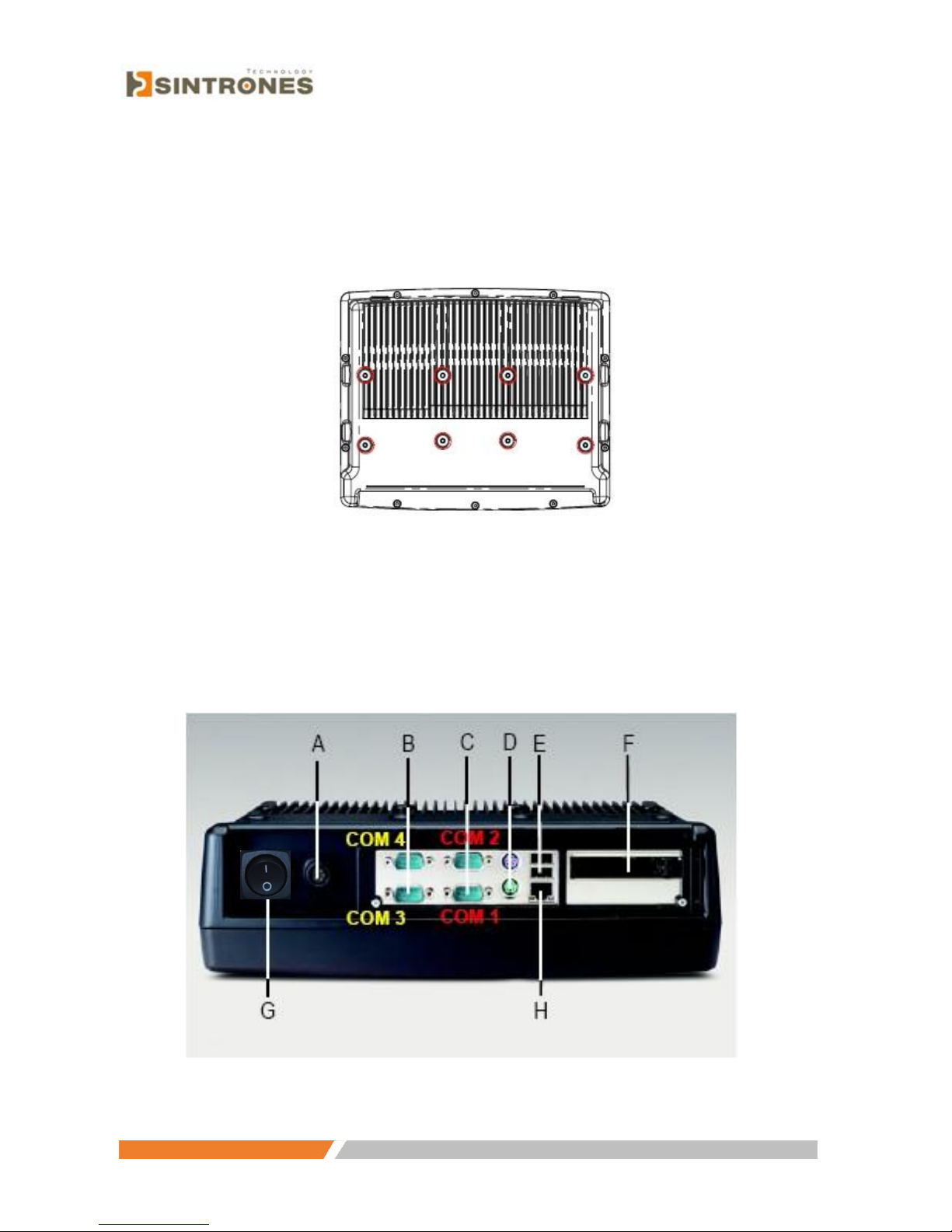
Turn the Vehicle Mounted Computer around to look at its rear cover. There are
VESA standard holes and others for mounting. There are no ventilation holes; see
Figure 2.3
Figure 2.3
The I/O section is located on the bottom of the Vehicle Mounted Computer, as
shown in Figure 2.4
Figure 2.4
Page 15

www.sintroncorp.com
Address: 2880 Zanker Rd, Suite 207, San Jose CA 95134 USA TEL: 408-800-1413 / FAX: 510-952-8282 / [email protected]
A: DC Power Inlet (IP66) E: 2 x USB 2.0
B: 2 Serial Ports (RS-232) F: PCMCIA Type II x 2 / Type III x 1
C: 2 Serial Ports (RS-232/422/485) G: Power Switch (IP65)
D: PS/2 Keyboard and Mouse Port H: 10/100 Base-T Ethernet
The Vehicle Mounted Computer provides brightness keys on the front panel of
VMT-825, beside the front bezel. Press "+" or "-" to increase or decrease
brightness; see Figure 2.5
Increase brightness
Decrease brightness
Figure 2.5
Page 16
www.sintroncorp.com
Address: 2880 Zanker Rd, Suite 207, San Jose CA 95134 USA TEL: 408-800-1413 / FAX: 510-952-8282 / [email protected]
2.2 Installation Procedures
2.2.1 Connecting the Power Cord
Connect the 5-pin power cord into the DC inlet of the Vehicle Mounted Computer.
On the other end of the cable, 6 pins are available to make connections to positive
and negative power voltages, as well as the ground and ignition signals. The pin
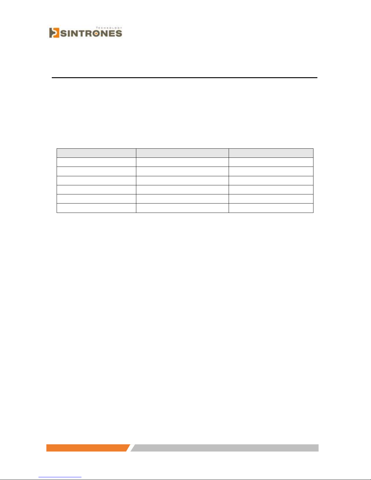
definition is illustrated in Table 2.1.
Pin
Definition
Color
1 + Brown
2 - Blue
3 + Green
4 - White
5
Ignition
Yellow
6
GND
Black
2.2.2 Connecting the Keyboard or Mouse
Before starting the computer, connect the necessary mouse or keyboard to the PS/2
mouse, keyboard port or serial ports.
2.2.3 Switching On the Power
The power switch is located on the bottom of the computer
Page 17

www.sintroncorp.com
Address: 2880 Zanker Rd, Suite 207, San Jose CA 95134 USA TEL: 408-800-1413 / FAX: 510-952-8282 / [email protected]
2.3 Running the BIOS Setup Program
The Vehicle Mounted Computer is likely to have been properly set up and
configured by your dealer prior to delivery. You may still find it necessary to use
the computer’s BIOS (Basic Input-Output System) setup program to change
system configuration information, such as the current date and time, or the type of
hard drive. The setup program is stored in read-only memory (ROM). It can be
accessed either when turning on, or when resetting the computer, by pressing the
"Del" key on the keyboard immediately after powering on.
The settings specified with the setup program are recorded in a special area of the
memory called CMOS RAM. This memory is backed up by a battery, and it will
not be erased when turning off or resetting the system. Whenever the power is
turned on, the system reads the settings stored in CMOS RAM and compares them
to the equipment check conducted during the power on self-test (POST). If an error
occurs, an error message will be displayed on the screen, and a prompt to run the
setup program appears.
2.4 Installing System Software
Recent releases of operating systems from major vendors include setup programs
which load automatically and guide the user through hard disk preparations and
installation of the operating system. The guidelines below will help determine the
steps necessary to install the operating system on the computer hard drive.
If required, insert the operating system’s installation or setup diskette into the
diskette drive until the release button pops out.
The BIOS of the computer supports system boot-ups directly from the CD-ROM
drive. It is also possible to insert the system installation CDROM into the
CD-ROM drive.
Page 18

www.sintroncorp.com
Address: 2880 Zanker Rd, Suite 207, San Jose CA 95134 USA TEL: 408-800-1413 / FAX: 510-952-8282 / [email protected]
Power on your computer, or reset the system by pressing the "Ctrl"+"Alt"+"Del"
keys simultaneously. The computer will automatically load the operating system
from the diskette or CD-ROM.
If presented with the opening screen of a setup or installation program, follow the
instructions on screen. The setup program will guide the user through preparation
of the hard drive and installation of the operating system.
If presented with an operating system command prompt, such as A:\>, then it is
necessary to partition and format the hard drive, and manually copy the operating
system files to it. Refer to the operating system user’s manual for instructions on
partitioning and formatting a hard drive.
2.5 Installing the Drivers
After installing system software, it is possible to set up multimedia programs found
in the utility directory on the CD-ROM. Some drivers and utilities in the CD-ROM
disc have their own text files which help users install the drivers and understand
their functions.
These files are a very useful supplement to the information in this manual.
For more details about driver installation, refer to Chapter 4 to 9 of
this manual.
Page 19

www.sintroncorp.com
Address: 2880 Zanker Rd, Suite 207, San Jose CA 95134 USA TEL: 408-800-1413 / FAX: 510-952-8282 / [email protected]
Chapter 3 Hardware and Peripheral Installation
3.1 Overview of Hardware Installation and Upgrading
The Vehicle Mounted Computer consists of a PC-based computer that is housed in
a ruggedized aluminum enclosure. Any maintenance or hardware upgrades can be
completed after removing both panels
3.2 Installing the Storage Device
The Vehicle Mounted Computer can apply either a 2.5" Hard Disk Drive (HDD),
or a Compact Flash Card (CFC) as storage devices, depending on system
requirements. Below, installation instructions for both kinds of devices are shown.
3.2.1 Installing the 2.5" hard disk drive (HDD)
It is possible to attach one enhanced Integrated Device Electronics (IDE) hard
disk drive to the computer’s internal controller, which uses a PCI local-bus
interface. The advanced IDE controller supports faster data transfers and allows
the IDE hard drive to exceed 528 MB. Follow the instructions below for
installation:
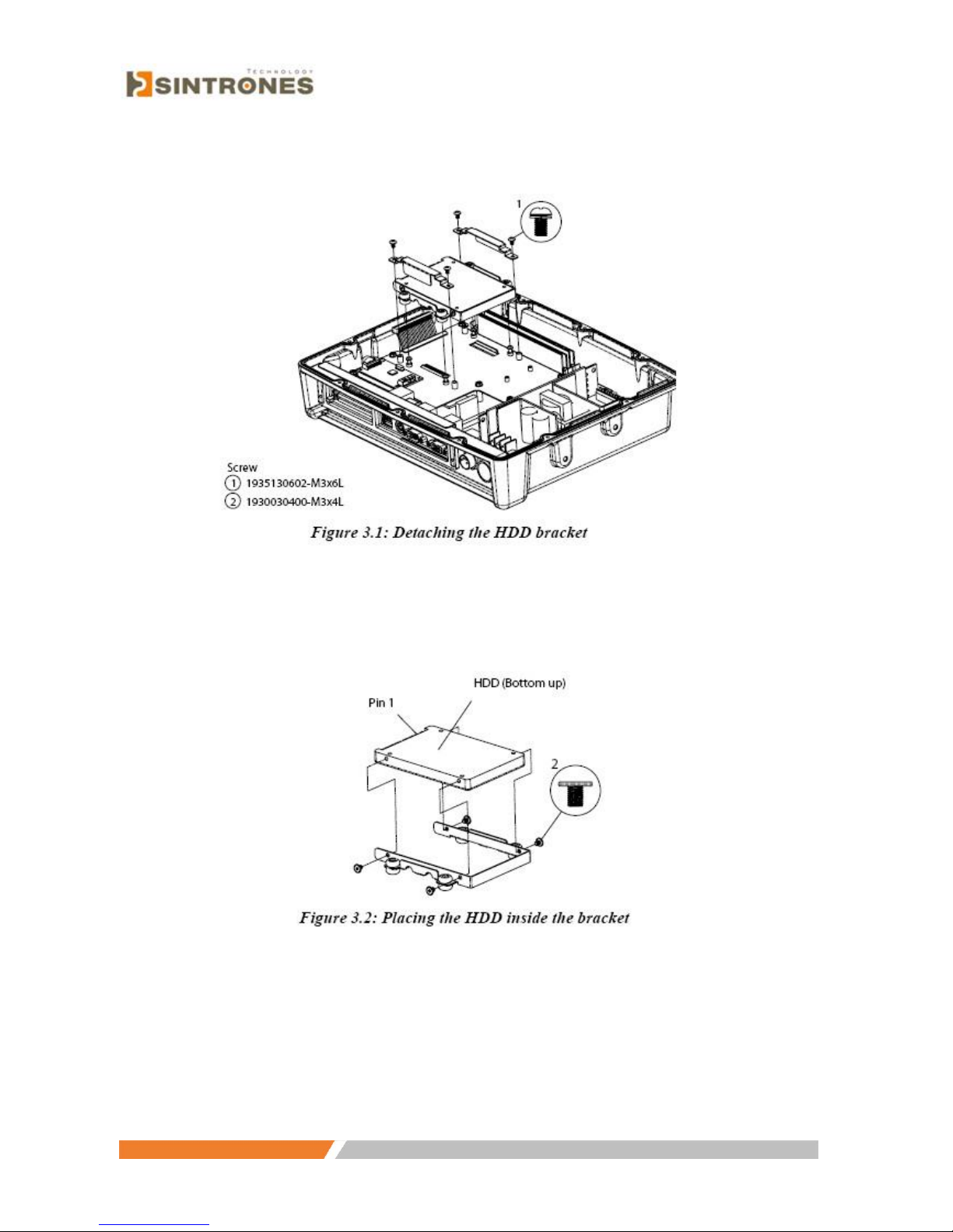
1. Detach the HDD bracket by unscrewing the four screws (#1) on the top of the
HDD bracket.
Page 20
www.sintroncorp.com
Address: 2880 Zanker Rd, Suite 207, San Jose CA 95134 USA TEL: 408-800-1413 / FAX: 510-952-8282 / [email protected]
2. Place the HDD inside the HDD bracket and tighten the four screws (#2) from
both sides of the HDD bracket
3. The HDD cable (1 x 44-pin to 1 x 44-pin) is located next to the HDD bracket.
Connect the HDD cable to the HDD. Make sure that the red wire corresponds to
Pin 1 on the connector, which is labeled on the board. Plug the other end of the
cable into the HDD, with Pin 1 on the cable corresponding to Pin 1 on the HDD.
Page 21
www.sintroncorp.com
Address: 2880 Zanker Rd, Suite 207, San Jose CA 95134 USA TEL: 408-800-1413 / FAX: 510-952-8282 / [email protected]
3.2.2 Installing the Compact Flash Card (CFC)
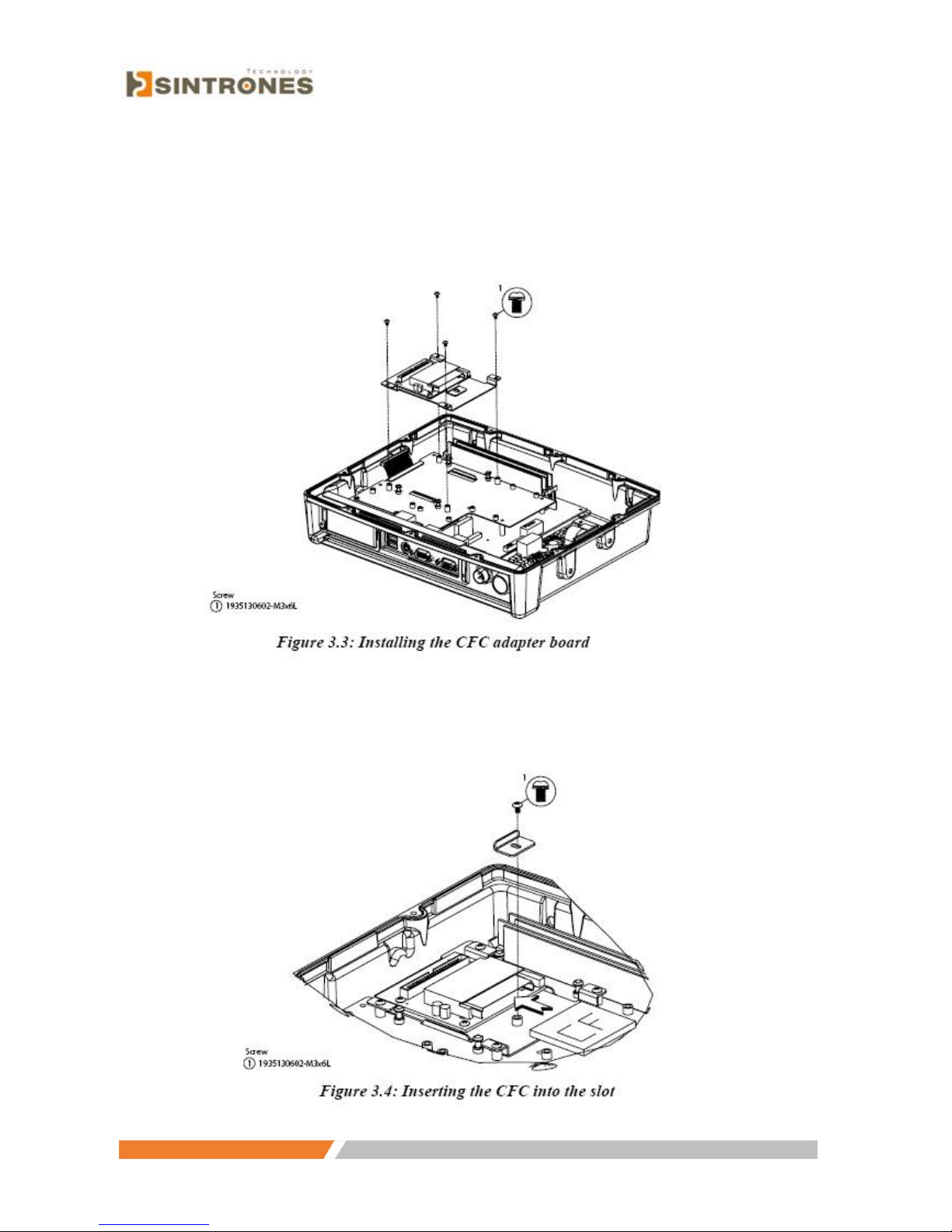
1. Install the CFC adapter board by screwing the four screws (#1) on the top of
the main frame.
2. Insert CFC into the slot on the adapter board and fix the CFC blocker by
tightening the screw (#1) on the adapter board
Page 22
www.sintroncorp.com
Address: 2880 Zanker Rd, Suite 207, San Jose CA 95134 USA TEL: 408-800-1413 / FAX: 510-952-8282 / [email protected]
3. The IDE cable (1 x 44-pin to 1 x 44-pin) is located next to the CFC adapter
board. Connect the IDE cable to the CFC. Make sure that the red wire
corresponds to Pin 1 on the connector, which is labeled on the board. Plug the
other end of the cable into the CFC, with Pin 1 on the cable corresponding to Pin
1 on the CFC.
3.3 Placing the Rubber Seal
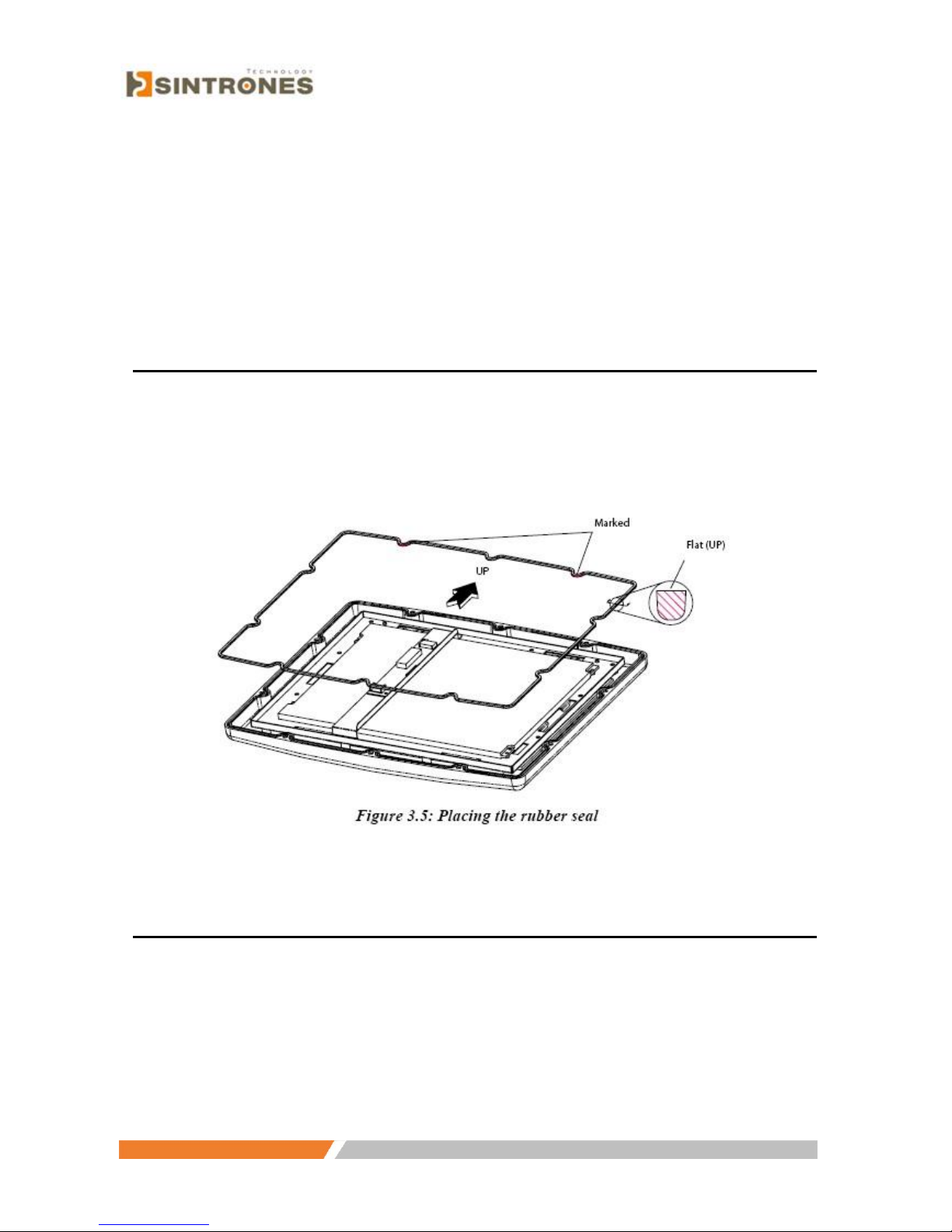
To ensure that the VMT-825 stays dry, the supplied rubber seal must be placed
correctly between the front bezel and the back cover. Please note the direction of
the seal: the flat, marked side should face up
3.4 Installing the Optional Accessories
Optional accessories are available for purchase for the VMT-825. They include
mounting kits and functional modules. The following instructions detail
accessories installation.
Page 23
www.sintroncorp.com
Address: 2880 Zanker Rd, Suite 207, San Jose CA 95134 USA TEL: 408-800-1413 / FAX: 510-952-8282 / [email protected]
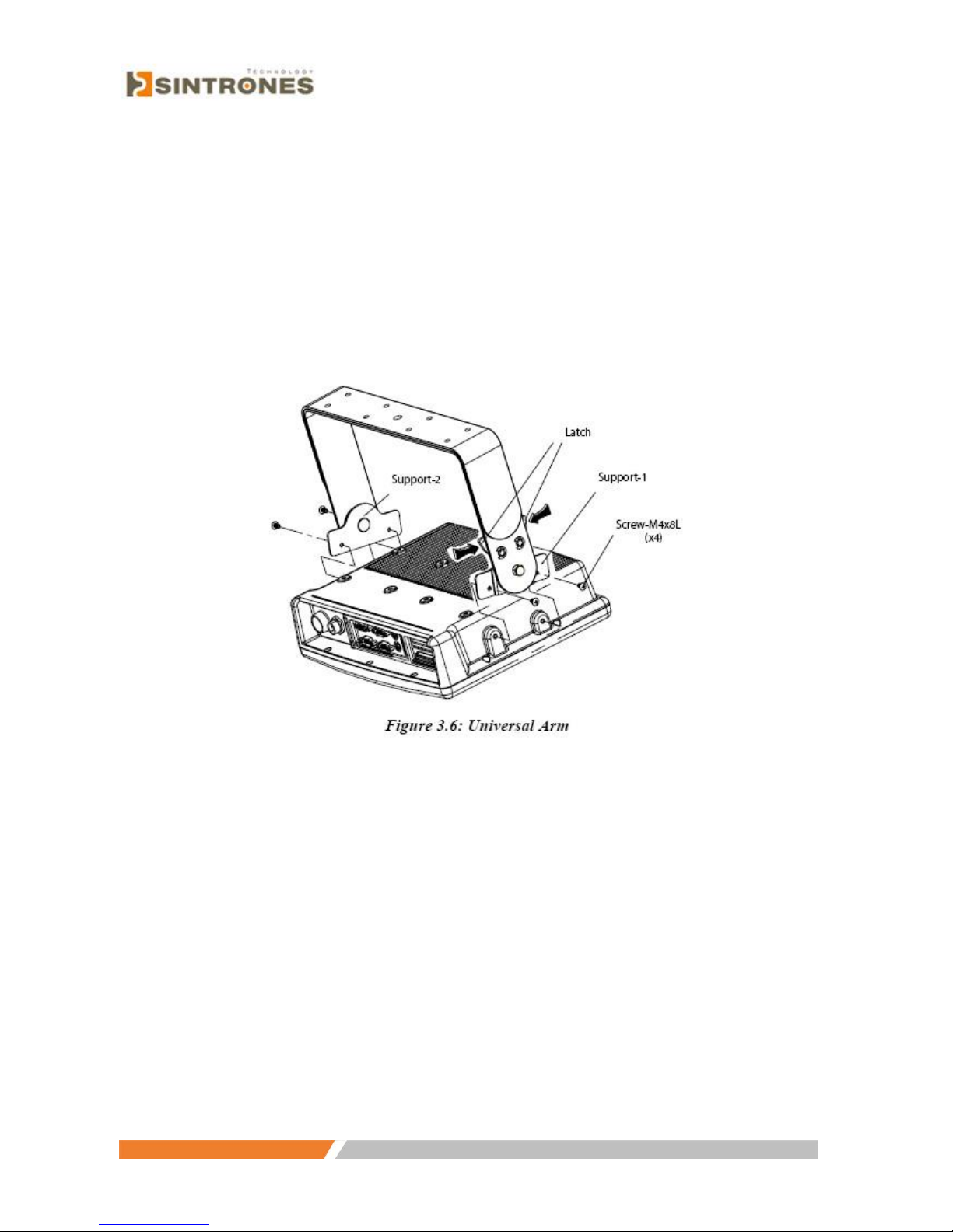
3.4.1 installing the .Universal Arm.
1. Press the latches at the same time and then rotate Support-1 until both screw
holes are visible.
2. Rotate Support-2 until the angle is the same as Support-1.
3. Use four M4 x 8L screws and attach the U-Arm with the VMT-825. The 4
stainless screws are supplied with the universal arm, inside the box.
4. Use the latches to adjust the angle of VMT-825 through 360° in 14.4° steps.
3.4.2 Installing RAM-MOUNT .kits.
Three different types of RAM-MOUNT kits are available to fit various
applications; RAM-MOUNT-01 and RAM-MOUNT-02 support units weighing
up to 4.5kg (approximate 10 lbs). RAM-MOUNT-03 mount supports units
weighing up to 6.75kg (approximate 15 lbs). However, each kit uses the same
mounting bracket plate for both the VMT-825.
Four M4 x 15L screws are required to affix the RAM-MOUNT bracket
plate to the rear cover of VMT-825 through the centrally
located VESA holes. It is also possible to install other parts of the RAMmount
kits, as pictured further below.
Page 24

www.sintroncorp.com
Address: 2880 Zanker Rd, Suite 207, San Jose CA 95134 USA TEL: 408-800-1413 / FAX: 510-952-8282 / [email protected]
3.4.3 Installing the MiniPCI WLAN module
1. Insert the WLAN module into the MiniPCI slot on the motherboard, (circle 1).
2. Attach the antenna cable to the main connector located on the WLAN module,
(circle 2). If adopting the dual antenna, attach the other antenna cable to the
AUX connector located on the WLAN module.
3. Attach the cable from the WLAN module to the internal antenna receptacle,
located on the top left side of the rear cover, (circle 3).
4. Screw the antenna into the external receptable, located on top of the outside
rear cover.
Page 25

www.sintroncorp.com
Address: 2880 Zanker Rd, Suite 207, San Jose CA 95134 USA TEL: 408-800-1413 / FAX: 510-952-8282 / [email protected]
Note: The default setting for MiniPCI LAN uses the antenna receptacle on the
left-hand side; if, for some reason, it is being used by another connection, an
extra cable of a different length is available on request for connection to the
extra receptacle on the right-hand side of the cover
3.4.4 Installing GPS and GSM/GPRS modules
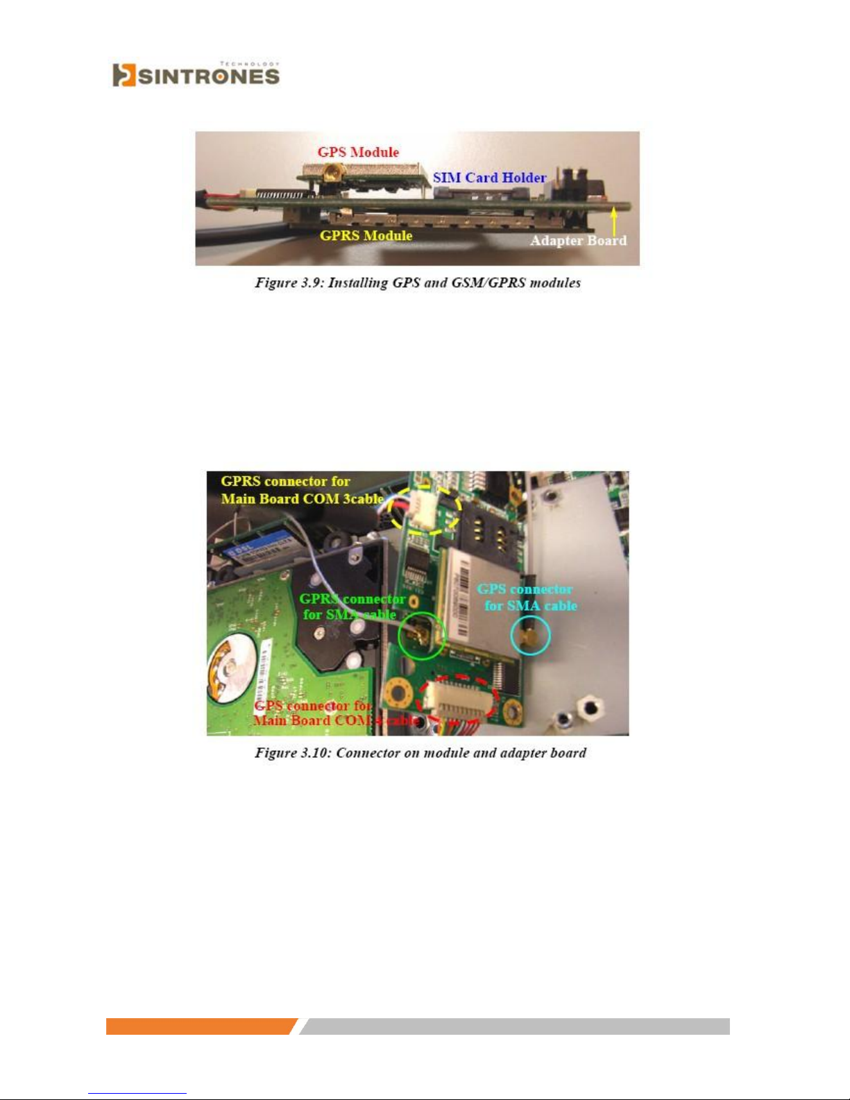
One module adapter board is designed to mount both the GPS and GSM/
GPRS modules, as pictured below. Follow the instructions:
A. Installing the GPS module:
1. Check that the GPS module is mounted onto the upper side of adapter board.
Page 26
www.sintroncorp.com
Address: 2880 Zanker Rd, Suite 207, San Jose CA 95134 USA TEL: 408-800-1413 / FAX: 510-952-8282 / [email protected]
2. Attach and tighten the antenna wire between the GPS module connector and
the antenna hole on rear cover. Then, connect the serial cable on the adapter
board to the COM3 port on the motherboard. See Figure 3.10 and 3.11 below.
3. Screw the antenna into the external antenna receptacle on the rear cover
B. Installing the GSM/GPRS module:
1. Check that the GSM/GPRS module is mounted onto the back side of the
adapter board.
2. Place the SIM card into the SIM card holder.
3. Tighten the wire between the GSM/GPRS module connector and the antenna
hole on the rear cover. Connect the cable on the adapter board with the COM4
port on motherboard. (See Figure 3.10 above for close location of the
Page 27

www.sintroncorp.com
Address: 2880 Zanker Rd, Suite 207, San Jose CA 95134 USA TEL: 408-800-1413 / FAX: 510-952-8282 / [email protected]
connectors.)
4. Screw the antenna into the antenna receptacle on the outside of the rear cover.
After installation is complete, the finished system resembles Figure 3.11:
Page 28
www.sintroncorp.com
Address: 2880 Zanker Rd, Suite 207, San Jose CA 95134 USA TEL: 408-800-1413 / FAX: 510-952-8282 / [email protected]
Chapter 4 Jumper Settings and Connectors
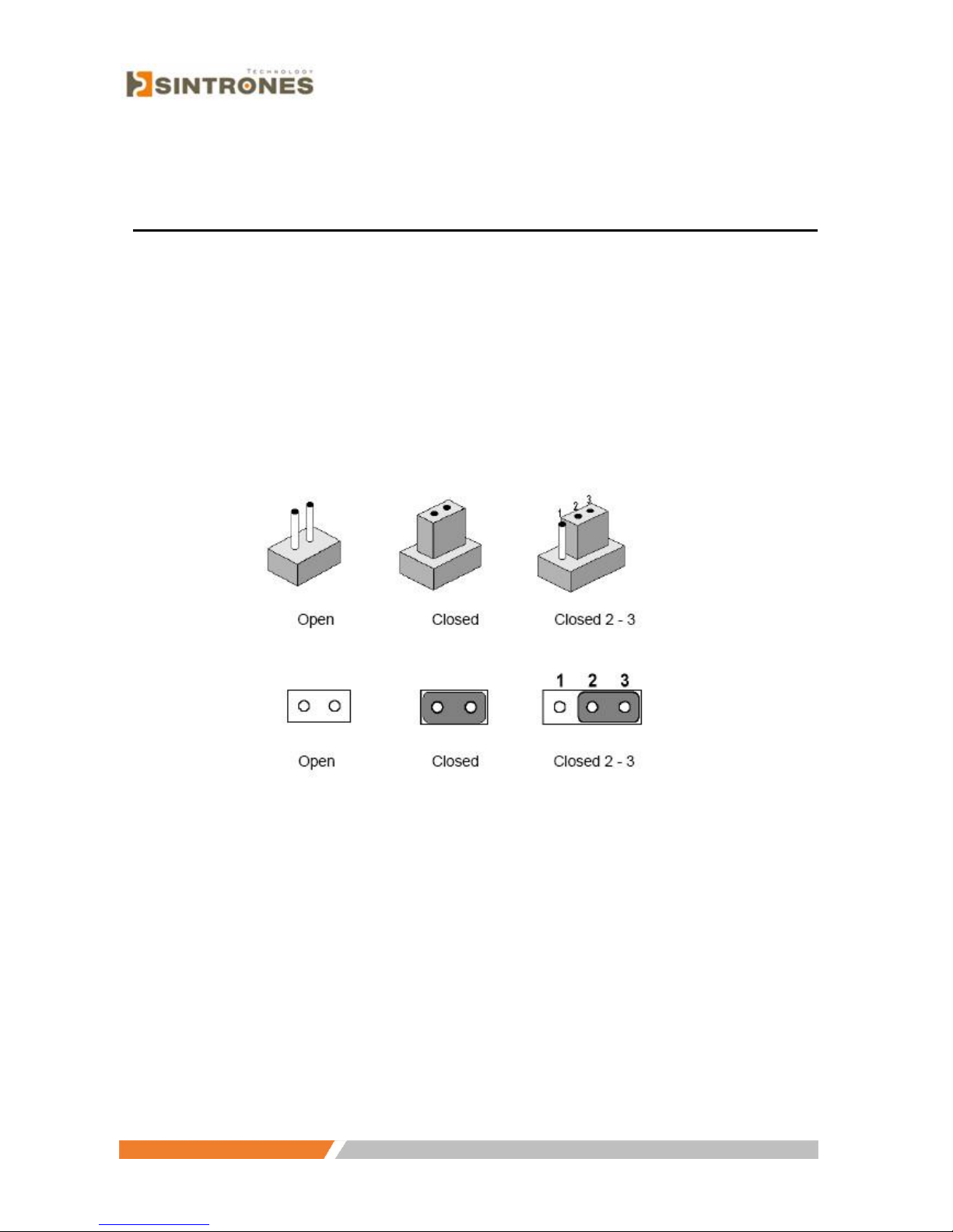
4.1 Setting Jumpers
The Vehicle Mounted Computer can be configured to match the needs of each
application by setting the jumpers. A jumper is the simplest kind of electrical
switch. It consists of two metal pins and a small metal clip (often protected by a
plastic cover), which slides over the pins to close the circuit and connect them.
To .close. a jumper, connect the pins with the clip. To .open. a jumper, remove the
clip. Sometimes a jumper has three pins, labeled 1, 2, and 3. In this case, it is
possible to connect either pins 1 and 2 or pins 2 and 3 to each other.
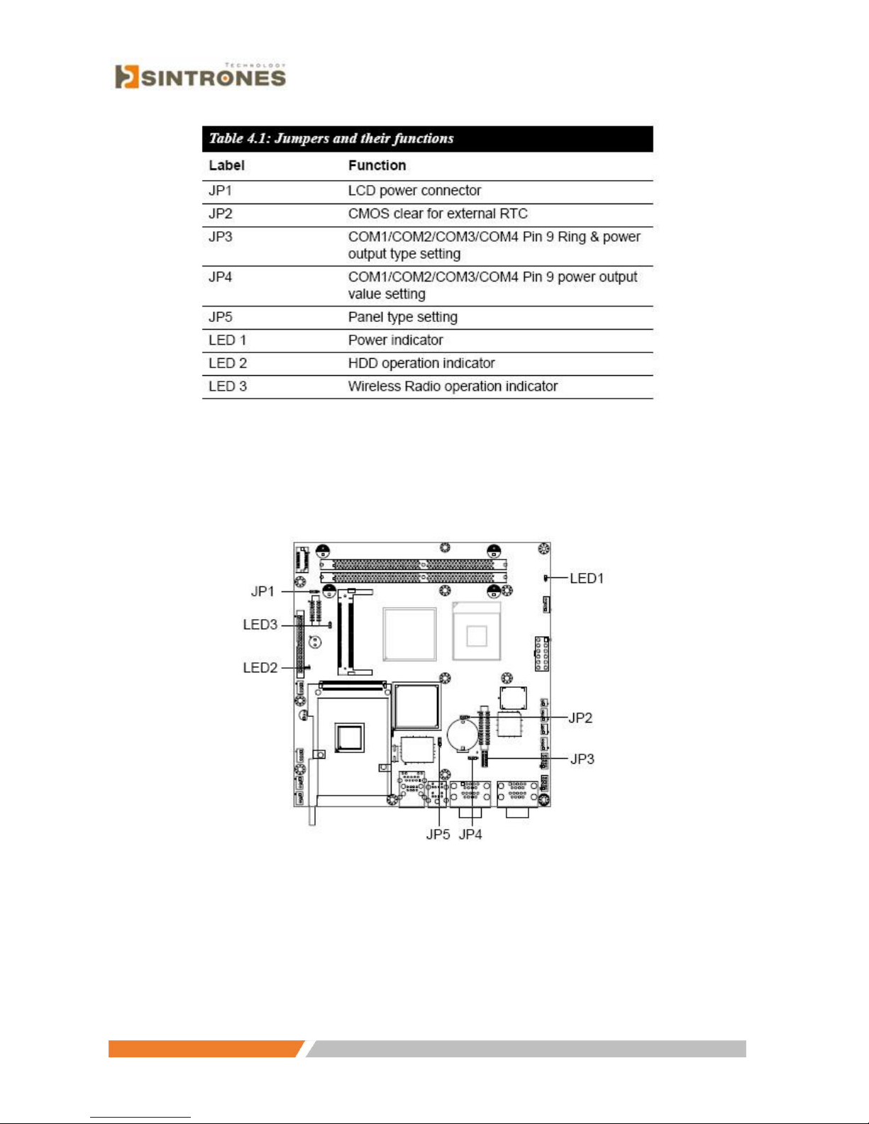
4.1.1 Jumpers and switches
The motherboard of the Vehicle Mounted Computer has a number of jumpers
that help configure the system. It also has LED indicator lamps that display the
system operation status. The table below lists the function of each jumper and
LED.
Page 29
www.sintroncorp.com
Address: 2880 Zanker Rd, Suite 207, San Jose CA 95134 USA TEL: 408-800-1413 / FAX: 510-952-8282 / [email protected]
4.1.2 Locating jumpers and switches
Page 30
www.sintroncorp.com
Address: 2880 Zanker Rd, Suite 207, San Jose CA 95134 USA TEL: 408-800-1413 / FAX: 510-952-8282 / [email protected]
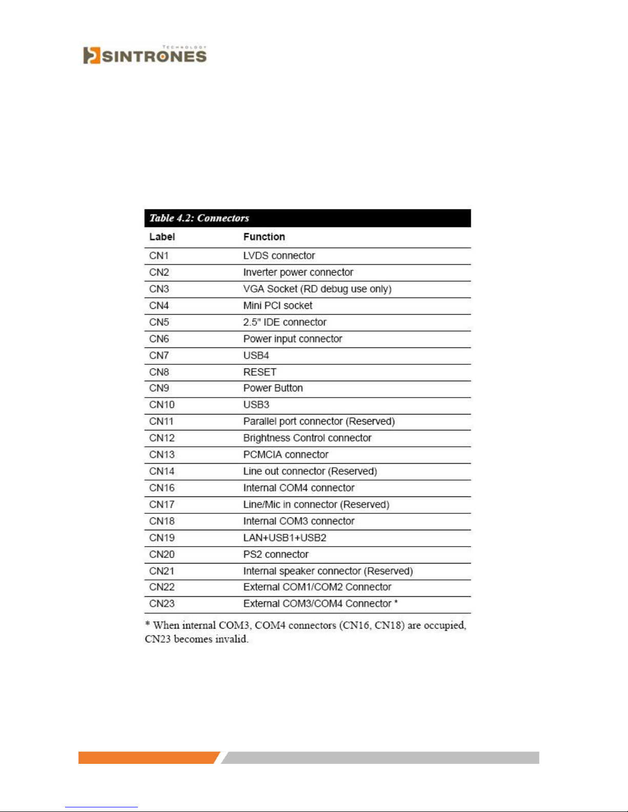
4.1.3 Connectors on the motherboard
On-board connectors link the Vehicle Mounted Computer to external devices
such as hard disk drives. The table below lists the function of each connector.
Page 31

www.sintroncorp.com
Address: 2880 Zanker Rd, Suite 207, San Jose CA 95134 USA TEL: 408-800-1413 / FAX: 510-952-8282 / [email protected]
4.1.4 Locating connectors on the motherboard
Page 32

www.sintroncorp.com
Address: 2880 Zanker Rd, Suite 207, San Jose CA 95134 USA TEL: 408-800-1413 / FAX: 510-952-8282 / [email protected]
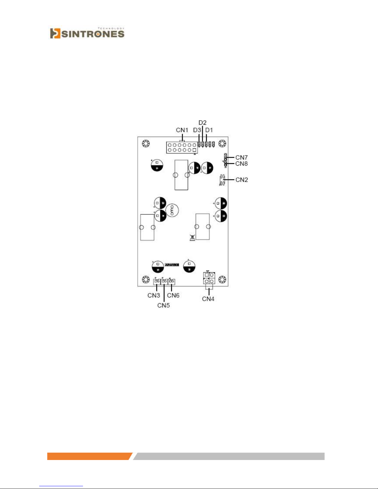
4.1.5 Jumpers and switches on power board
The power board of the Vehicle Mounted Computer has a number of
jumpers that help configure the system. It also has LED indicator lamps
that display the system operation status. The table below lists the function
of each connector and LED
Page 33
www.sintroncorp.com
Address: 2880 Zanker Rd, Suite 207, San Jose CA 95134 USA TEL: 408-800-1413 / FAX: 510-952-8282 / [email protected]
4.1.6 Locating jumpers, connectors and LEDs on power board
Page 34

www.sintroncorp.com
Address: 2880 Zanker Rd, Suite 207, San Jose CA 95134 USA TEL: 408-800-1413 / FAX: 510-952-8282 / [email protected]
4.2 CPU Installation
The CPU is embedded on the motherboard, so there are no settings for frequency
ratio or voltage.
4.3 Jumper Settings on Mother-Board
4.3.1 LCD panel power setting (JP1)
The Vehicle Mounted Computer’s AGP interface supports 5 V and 3.3 V LCD
displays. The default setting is 3.3 V (closed pins 1 and 2), but JP1 can be used
to change this to 5 V by closing pins 2 and 3.
4.3.2 Panel Type Setting (JP5)
When the .panel type. value is set to . HW default. in BIOS, the JP5 can be
used to set the panel type to support either 800 x 600 or 1024 x 768 LCD
resolution. The default jumper setting for 800 x 600 in the VMT-825 closes
pins 1 and 2;
Page 35

www.sintroncorp.com
Address: 2880 Zanker Rd, Suite 207, San Jose CA 95134 USA TEL: 408-800-1413 / FAX: 510-952-8282 / [email protected]
4.3.3 CMOS clear for external RTC (JP2)
Warning! To avoid damaging the computer, always turn off the power
supply before closing pins 2 and 3 to .Clear CMOS.. Reset the
jumper to .Normal operation. before turning on the power supply.
Page 36
www.sintroncorp.com
Address: 2880 Zanker Rd, Suite 207, San Jose CA 95134 USA TEL: 408-800-1413 / FAX: 510-952-8282 / [email protected]
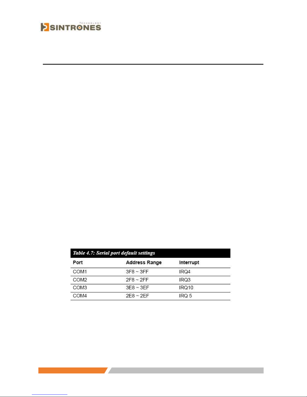
4.4 COM-port Interface
The computer provides four serial ports: COM1, COM 2: RS-232/422/485
(selectable via BIOS setting) and COM3, COM 4: RS-232.
The IRQ and the address ranges for COM1, COM2, COM3 and COM4 are fixed.
However, if it becomes necessary to disable the port or change these parameters
later, it is possible to do so through the system BIOS setup. The table overleaf
shows the default settings for the computer’s serial ports.
COM1 and COM2 are linked as one set. It is possible to exchange the address
range and interrupt IRQ of COM1 for the address range and interrupt IRQ of
COM2. After exchanging:
COM1’s address range is 2F8 ~ 2FF and its IRQ is IRQ3.
COM2’s address range is 3F8 ~ 3FF and its IRQ is IRQ4.
COM3 and COM4 are linked as another set. It is possible to exchange the address
range and interrupt IRQ of COM3 for the address range and interrupt IRQ of
COM4. After exchanging:
COM3’s address range is 3E8 ~ 3EF and its IRQ is IRQ10.
COM4’s address range is 2E8 ~ 2EF and its IRQ is IRQ5
Page 37
www.sintroncorp.com
Address: 2880 Zanker Rd, Suite 207, San Jose CA 95134 USA TEL: 408-800-1413 / FAX: 510-952-8282 / [email protected]
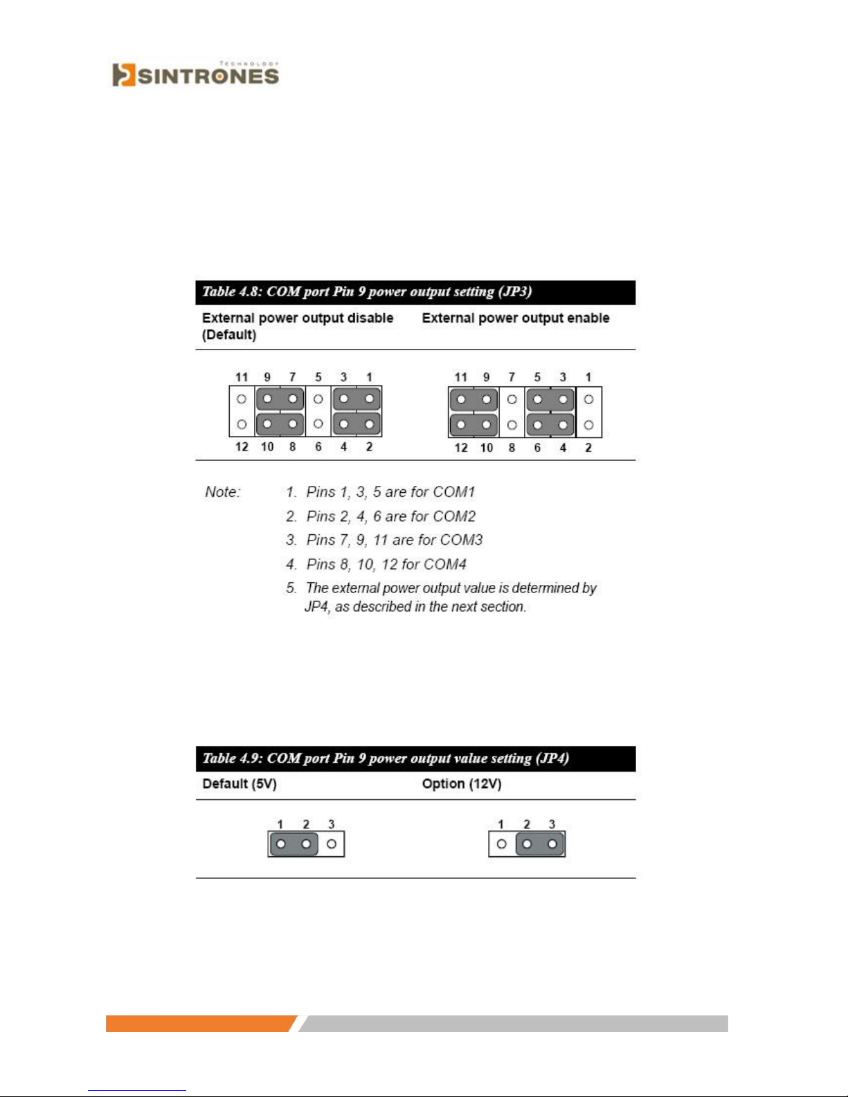
4.4.1 COM port Pin 9 power output setting (JP3)
Pin 9 on COM port can act as power output, and the settings available are
shown as below:
4.4.2 COM port Pin 9 power output value setting (JP4)
Page 38
www.sintroncorp.com
Address: 2880 Zanker Rd, Suite 207, San Jose CA 95134 USA TEL: 408-800-1413 / FAX: 510-952-8282 / [email protected]
4.5 Jumper Setting on Power-Board
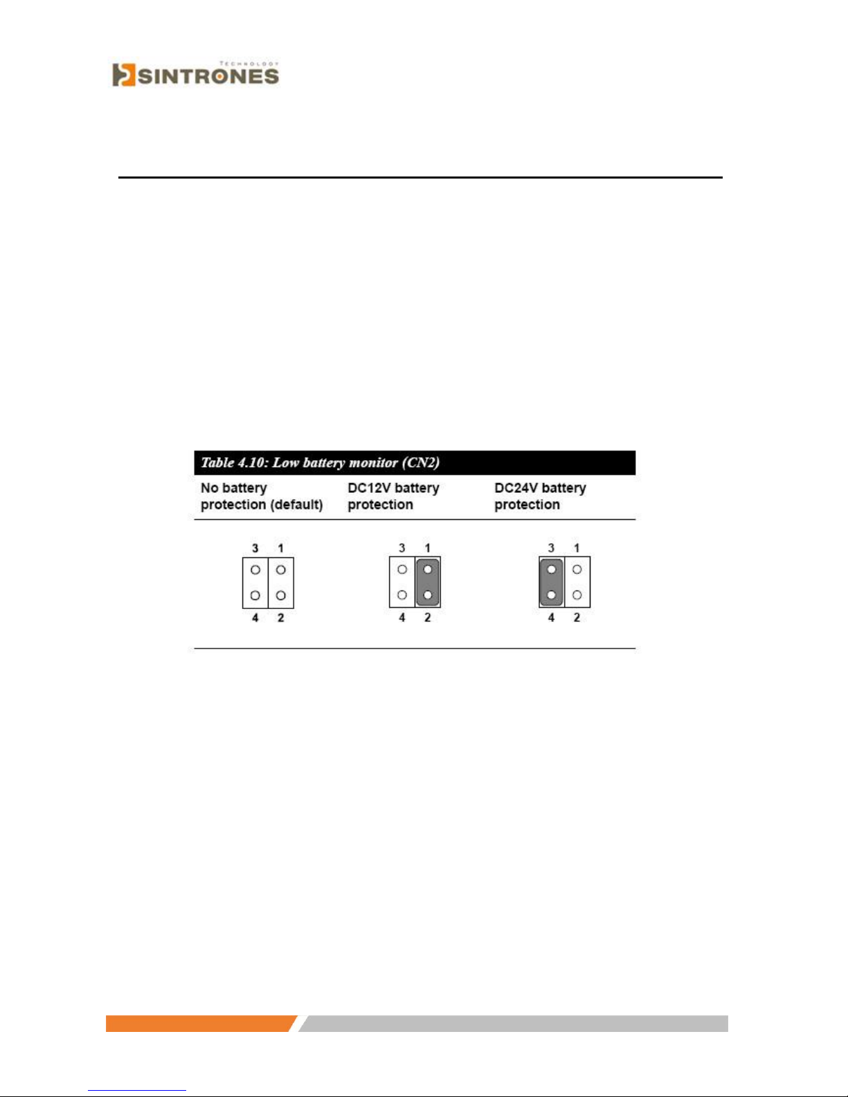
4.5.1 Low battery monitor and shut down (CN2)
The low battery monitor is an optional shut down function designed to prevent
the DC vehicle battery power from running out. When the battery voltage drops
below a certain level (11V for DC12V battery, and 22V for DC24V battery) the
OS will be terminated after 30 seconds and the system power will shut down
after one minute.
The default setting reserves all pins open to disable the shut down function.
However, DC24V battery protection can be activated by closing
pins 3 - 4, or changed to DC12V battery protection by closing pins 1 - 2.
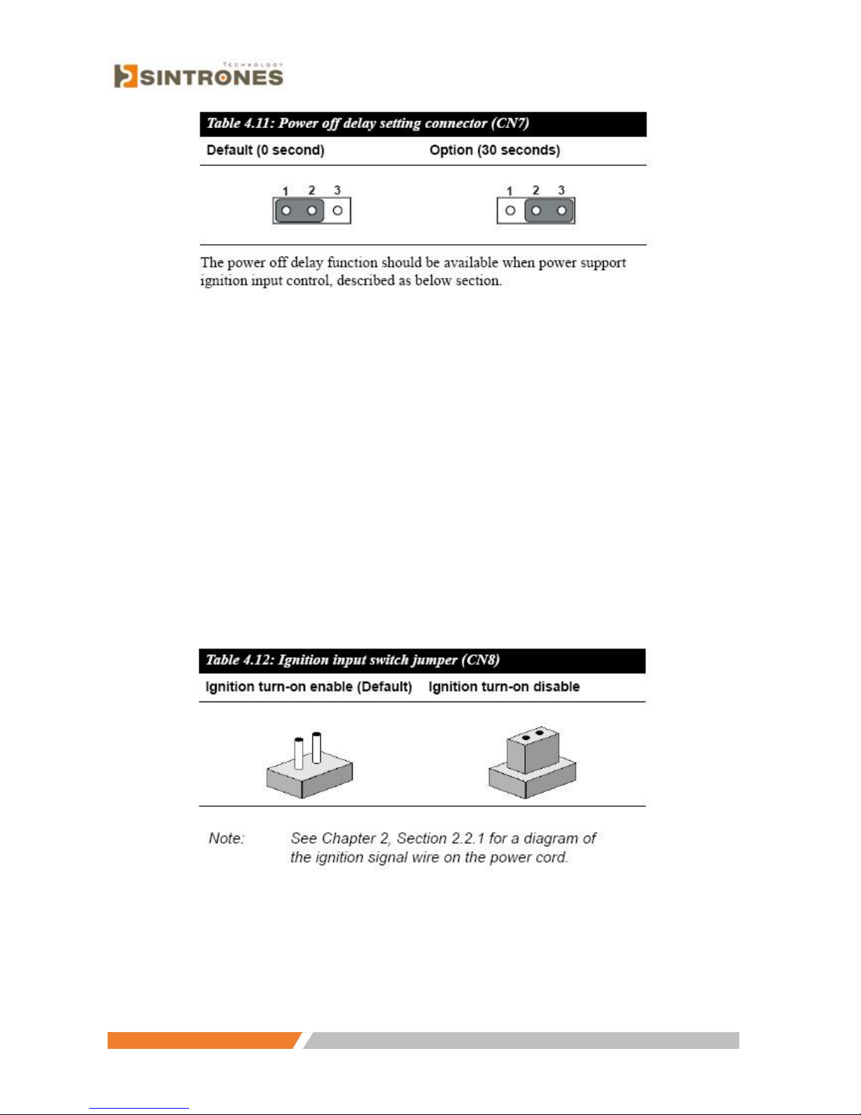
4.5.2 Power off delay setting connector (CN7)
This connector determines the delay time when the power turns off and
provides two kinds of settings; shut down at 0 seconds, or 30 seconds after the
power turns off. To change the delay time, Sintron accepts OEM design
requests. The standard setting is shown below:
Page 39
www.sintroncorp.com
Address: 2880 Zanker Rd, Suite 207, San Jose CA 95134 USA TEL: 408-800-1413 / FAX: 510-952-8282 / [email protected]
4.5.3 Ignition input switch jumper (CN8)
This jumper determines if the Vehicle Mounted Computer can be activated
by linkage to a vehicle ignition switch.
The default setting reserves the jumper open. To enable the power-on function
via the vehicle ignition switch, it is necessary to change the power fail function
setting from BIOS (See Appendix B.2) and connect the signal pin of the power
cord supplied with the TREK (See Section 2.2.1) to the car engine circuit. This
function can be disabled by either
closing the jumper or connecting the signal pin of the power cord with the
anode of car battery. The setting is shown below:
Page 40

www.sintroncorp.com
Address: 2880 Zanker Rd, Suite 207, San Jose CA 95134 USA TEL: 408-800-1413 / FAX: 510-952-8282 / [email protected]
Chapter 5 Intel Chipset
5.1 Introduction
The VMT-825 combines Intel® 855GME GMCH North Bridge with Intel®
82801DB I/O Controller Hub 4 (ICH-4) south bridge.
The Intel® 855GME chipset is an innovative integrated graphics chipset developed
with DDR333 memory. It is optimized to support the Intel Pentium ® M /
Celeron® M processor, adding intelligence to help manage and prioritize multiple
threads received from the microprocessor. The Intel 855GME chipset also includes
extremely stable and innovative Intel Extreme Graphics technology, running at 266
MHz core speed.
The Intel 82801DB I/O Controller Hub 4 (ICH4) is a highly integrated
multifunctional I/O Controller Hub that provides an interface to the PCI Bus and
integrates many of the functions needed in today’s PC platforms.
5.1.1 Installation for Windows 98
1. Execute D:\CHIPSET\Win9x\infinst_enu.exe
2. Press .Next. to proceed, then follow the on-screen instructions.
3. Choose .Yes, I want to restart my computer,. and press .Finish..
The system reboots automatically
5.1.2 Installation for Windows 2000 / XP
1. Execute D:\CHIPSET\Win2K_XP\infinst_autol.exe
2. Press .Next. to proceed, and .Software License Agreement. Dialog box
appears. Click .Yes..
3. Press .Next. to proceed.
4. Choose .Yes, I want to restart my computer,. and press .Finish..The system
reboots automatically.
Page 41

www.sintroncorp.com
Address: 2880 Zanker Rd, Suite 207, San Jose CA 95134 USA TEL: 408-800-1413 / FAX: 510-952-8282 / [email protected]
5.2 Further Information
For further information about the Intel chipset installation in VMT-825, including
driver updates, troubleshooting guides and FAQ lists, visit the following web sites:
Intel website: www.Intel.com
Sintron websites: www.sintroncorp.com
Page 42

www.sintroncorp.com
Address: 2880 Zanker Rd, Suite 207, San Jose CA 95134 USA TEL: 408-800-1413 / FAX: 510-952-8282 / [email protected]
Chapter 6 Graphic Chipset
6.1 Introduction
The VMT-825 has an on-board integrated VGA chipset. The specifications and
features are described as follows.
6.1.1 Installation for Windows 2000 / XP
1. Execute D:\ Graphic\ win2k_xp141950.exe
2. Press .Next. to proceed, then follow the on-screen instructions.
3. When .Software License Agreement. dialog box appears. Click.Yes..
4. Choose .Yes, I want to restart my computer,. and press .Finish.. The system
reboots automatically.
6.2 Further Information
For further information about the Intel chipset installation in VMT-825, including
driver updates, troubleshooting guides and FAQ lists, visit the following web sites:
Intel website: www.intel.com
Sintron website: www.sintroncorp.com
Page 43

www.sintroncorp.com
Address: 2880 Zanker Rd, Suite 207, San Jose CA 95134 USA TEL: 408-800-1413 / FAX: 510-952-8282 / [email protected]
Chapter 7 Audio
7.1 Introduction
The ALC650 is an 18-bit, full duplex AC’97 2.2 compatible stereo audio CODEC
designed for PC multimedia systems, including host/soft audio and AMR/CNR
based designs. The ALC650 AC’97 CODEC supports multiple CODEC extensions
with independent variable sampling rates and built-in 3D effects.
7.2 Installation of Audio Driver
Before installing the audio driver, please take note of the procedures detailed
below. It is essential to know which operating system being applied to the
VMT-825, and then refer to the corresponding installation procedures.
1. Execute D:\ Audio\ALC650\WDM_A386.exe
2. Follow the on-screen instructions.
3. Choose .Yes, I want to restart my computer,. and press .Finish..
The system will reboot automatically.
Page 44

www.sintroncorp.com
Address: 2880 Zanker Rd, Suite 207, San Jose CA 95134 USA TEL: 408-800-1413 / FAX: 510-952-8282 / [email protected]
Chapter 8 USB 2.0
8.1 Introduction
Before installing the USB driver, please take note of the procedures detailed below.
It is important to know which operating system being applied to the VMT-825, and
then refer to the corresponding installation procedure. This USB driver only needs
to be installed under Window 98 / 2000 and is not necessary for WinXP.
8.2 Installation of USB Driver
1. Execute D:\ USB\ usb2k51.exe
2. Decide the path you want to install and press .Next. to proceed.
3. Follow the on-screen instructions.
4. Choose .Yes, I want to restart my computer,. and press .Finish..
The system reboots automatically
Page 45

www.sintroncorp.com
Address: 2880 Zanker Rd, Suite 207, San Jose CA 95134 USA TEL: 408-800-1413 / FAX: 510-952-8282 / [email protected]
Chapter 9 Touch Screen
9.1 Introduction
9.1.1 General information
The touch screen for the VMT-825 series is a resistive touch screen.
The resistive touch screen incorporates advanced second-generation resistive,
impact-resistant technology, which creates 80% light transmission. There is
also an antiglare surface for greatly enhanced visual resolutions. It also has a
new and improved scratch-resistant feature.
For more detailed information, please visit the following websites:
www.dynapro.com
www.amtouch.com.tw
Sintron reserves the right to alter the touch screen at any time without notice.
9.1.2 General specifications
Please refer to Chapter 1, Section 1.2 of this manual.
Page 46

www.sintroncorp.com
Address: 2880 Zanker Rd, Suite 207, San Jose CA 95134 USA TEL: 408-800-1413 / FAX: 510-952-8282 / [email protected]
9.2 Installation of Touch Sscreen Driver
The touch screen driver for Windows contains a native, 32-bit driver and a 32-bit
control panel program for the VMT-825 system. To facilitate installation of the
touch screen driver, you should read the instructions in this section carefully before
you attempt installation.
9.2.1 Windows 98-Me-2000-2003 driver
To install the software to the computer, the VMT-825 must have both a
Windows 98/Me/2000/2003 system running and PenMount control board
already installed. If an older version of the PenMount Windows
98/Me/2000/2003 driver is installed in the VMT-825, remove it first.
Follow the steps below to install the PenMount Windows 98/Me/2000/
2003 driver:
1. Click .Cancel. when the .Unknown Device. dialog box appears after
starting the system.
2. Execute .D:\ TouchScreen\Penmount USB\Driver\PenMount USB
Windows 98-Me-2000-2003 Driver\setup.exe. to install the Pen-Mount
Windows 98/Me/2000/2003 driver.
3. When PenMount logo, copying .PenMount USB- installation wizard .
and .welcome" message appears. Click .Next..
4. The .Software License Agreement. dialog box appears. Click .Yes..
5. The .Information. dialog box appears. Click .Next..
6. The .Choose Destination Location. dialog box appears. Type a PenMount
Utilities installation folder, or accept the default. Click .Next..
7. The "Select Program Folder" dialog box appears. Type a PenMount
Utilities program folder, or accept the default. Click .Next..
8. The .Start Copying Files. dialog box appears. Click "Next" to start
copying files to the system.
9. The .Setup Complete. dialog box appears. Click .Finish..
10. The .Restarting Windows. dialog box appears. Click .Yes I want to
restart my computer now;. then click .OK. to restart your computer.
Page 47

www.sintroncorp.com
Address: 2880 Zanker Rd, Suite 207, San Jose CA 95134 USA TEL: 408-800-1413 / FAX: 510-952-8282 / [email protected]
9.2.2 Windows XP driver
To install the software to the computer, the VMT-825 must have a Windows
XP system running and PenMount control board already installed. If an older
version of the PenMount Windows 98/Me/2000/2003 driver is installed in the
VMT-825, remove it first.
Follow the steps below to install the PenMount Windows XP driver:
1. Execute .D:\TouchScreen\Penmount USB\Driver\PenMount USB Windows
XP WHQL Driver\setup.exe. to install the PenMount Windows XP driver
and press .Next. to proceed.
2. Press .Next. and follow the on-screen instructions; then press "install" to
start
3. The .Restarting Windows. dialog box appears. Click .Yes I want to restart
my computer now,. then click .OK. to restart your computer.
9.3 Further Information
Sintron: www.sintroncorp.com
Salt: www.salt.com.tw
AMT: www.amtouch.com.tw
Page 48
www.sintroncorp.com
Address: 2880 Zanker Rd, Suite 207, San Jose CA 95134 USA TEL: 408-800-1413 / FAX: 510-952-8282 / [email protected]
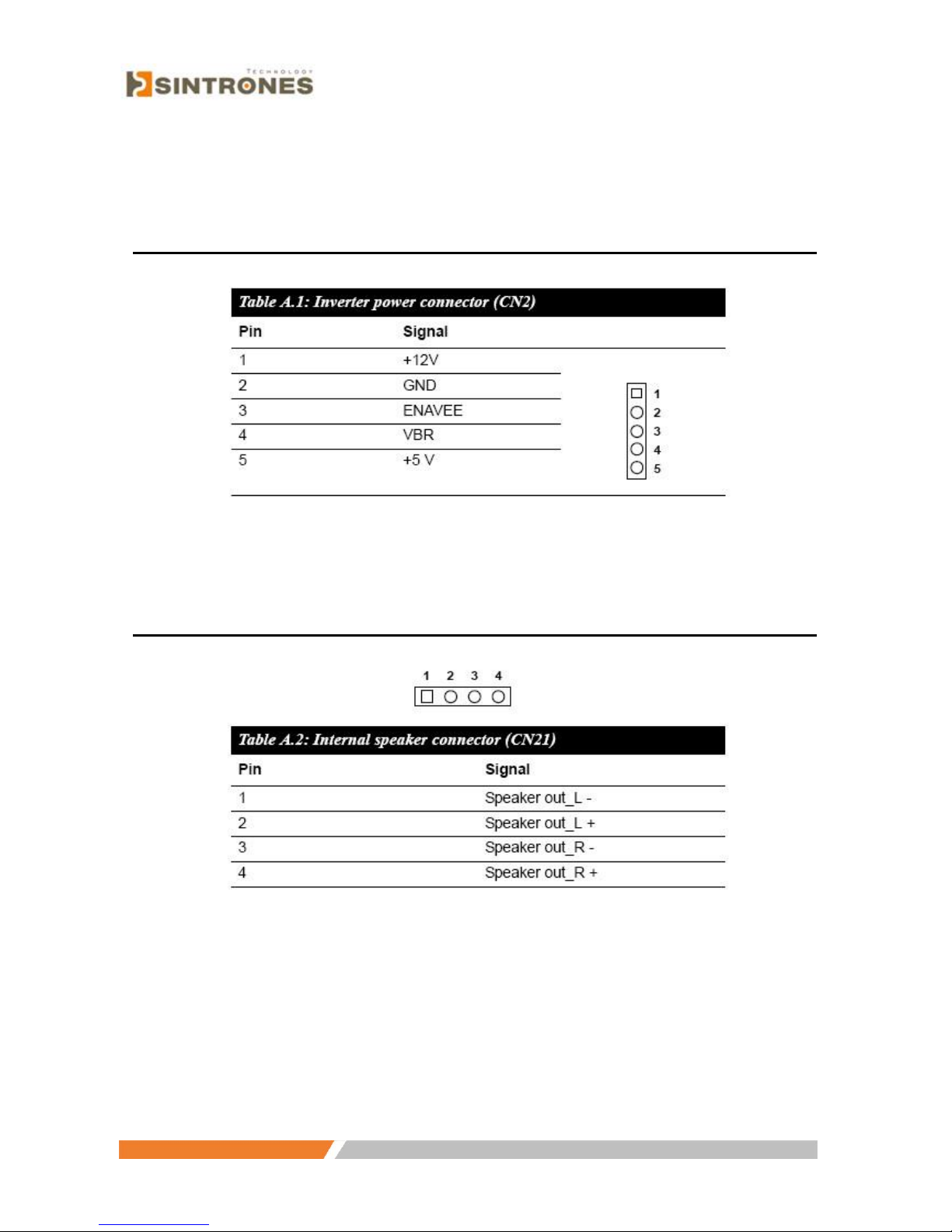
Appendix A Pin Assignments
A.1 Inverter power connector (CN2)
A.2 Internal speaker connector (CN21)
Page 49

www.sintroncorp.com
Address: 2880 Zanker Rd, Suite 207, San Jose CA 95134 USA TEL: 408-800-1413 / FAX: 510-952-8282 / [email protected]
A.3 IDE hard disk drive connector (CN5)
Page 50
www.sintroncorp.com
Address: 2880 Zanker Rd, Suite 207, San Jose CA 95134 USA TEL: 408-800-1413 / FAX: 510-952-8282 / [email protected]
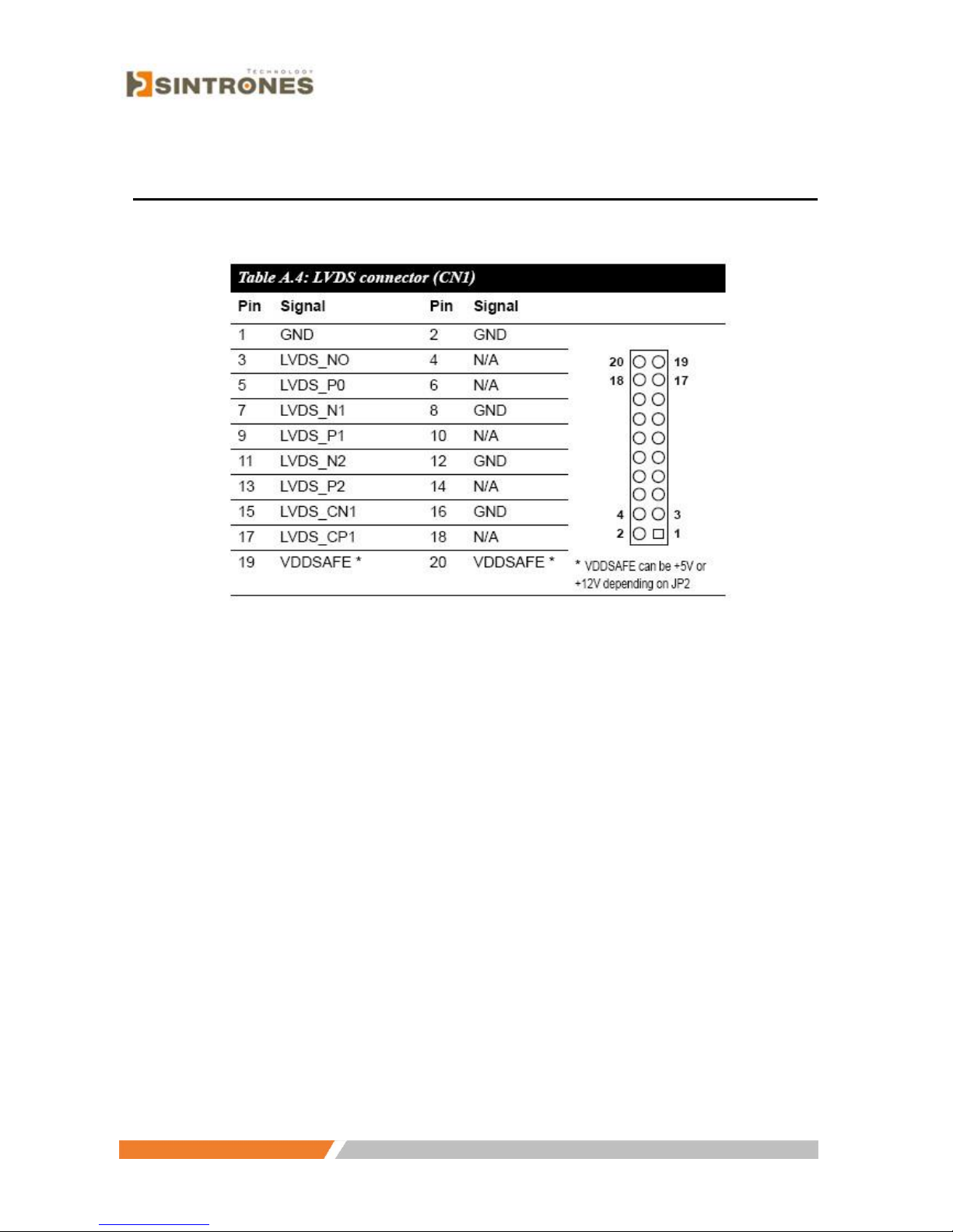
A.4 LVDS connector (CN1)
Page 51
www.sintroncorp.com
Address: 2880 Zanker Rd, Suite 207, San Jose CA 95134 USA TEL: 408-800-1413 / FAX: 510-952-8282 / [email protected]
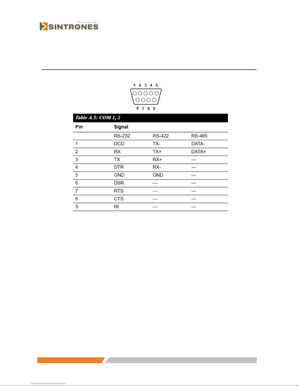
A.5 COM 1, 2
Page 52

www.sintroncorp.com
Address: 2880 Zanker Rd, Suite 207, San Jose CA 95134 USA TEL: 408-800-1413 / FAX: 510-952-8282 / [email protected]
A.6 COM 3, 4
Page 53

www.sintroncorp.com
Address: 2880 Zanker Rd, Suite 207, San Jose CA 95134 USA TEL: 408-800-1413 / FAX: 510-952-8282 / [email protected]
A.7 COM 3, 4 internal connector (CN18, 16)
Page 54
www.sintroncorp.com
Address: 2880 Zanker Rd, Suite 207, San Jose CA 95134 USA TEL: 408-800-1413 / FAX: 510-952-8282 / [email protected]
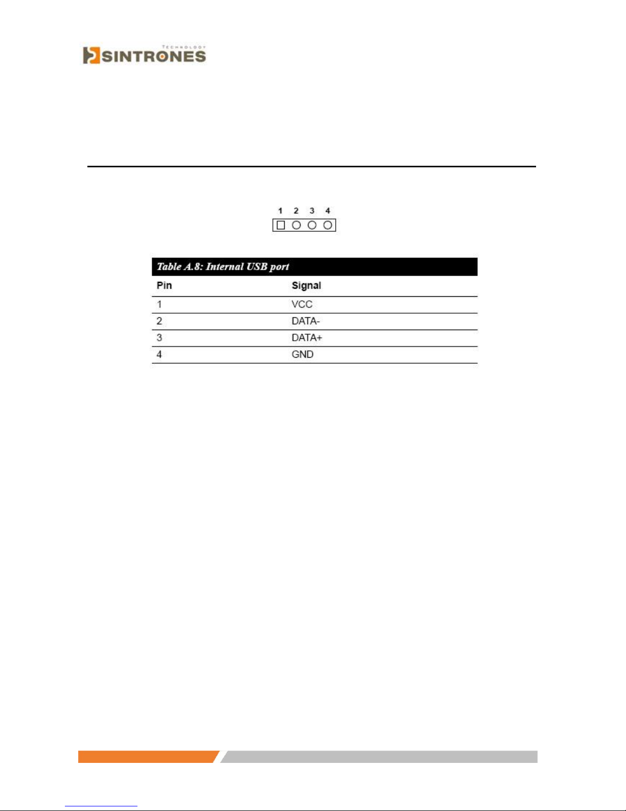
A.8 Internal USB port
Page 55

www.sintroncorp.com
Address: 2880 Zanker Rd, Suite 207, San Jose CA 95134 USA TEL: 408-800-1413 / FAX: 510-952-8282 / [email protected]
A.9 Reserved Parallel port connector (CN11)
Page 56

www.sintroncorp.com
Address: 2880 Zanker Rd, Suite 207, San Jose CA 95134 USA TEL: 408-800-1413 / FAX: 510-952-8282 / [email protected]
A.10 Power Inlet
Page 57
www.sintroncorp.com
Address: 2880 Zanker Rd, Suite 207, San Jose CA 95134 USA TEL: 408-800-1413 / FAX: 510-952-8282 / [email protected]
Appendix B Key Features Setting in BIOS
B.1 Panel Type Setting in BIOS
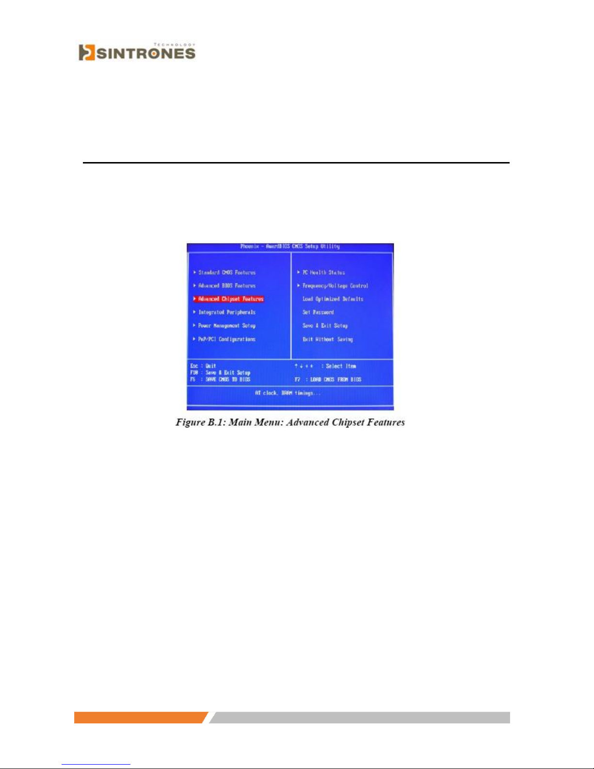
For setting the panel type in BIOS, follow these instructions:
1. Choose .Advanced Chipset Feature. in the main menu of BIOS.
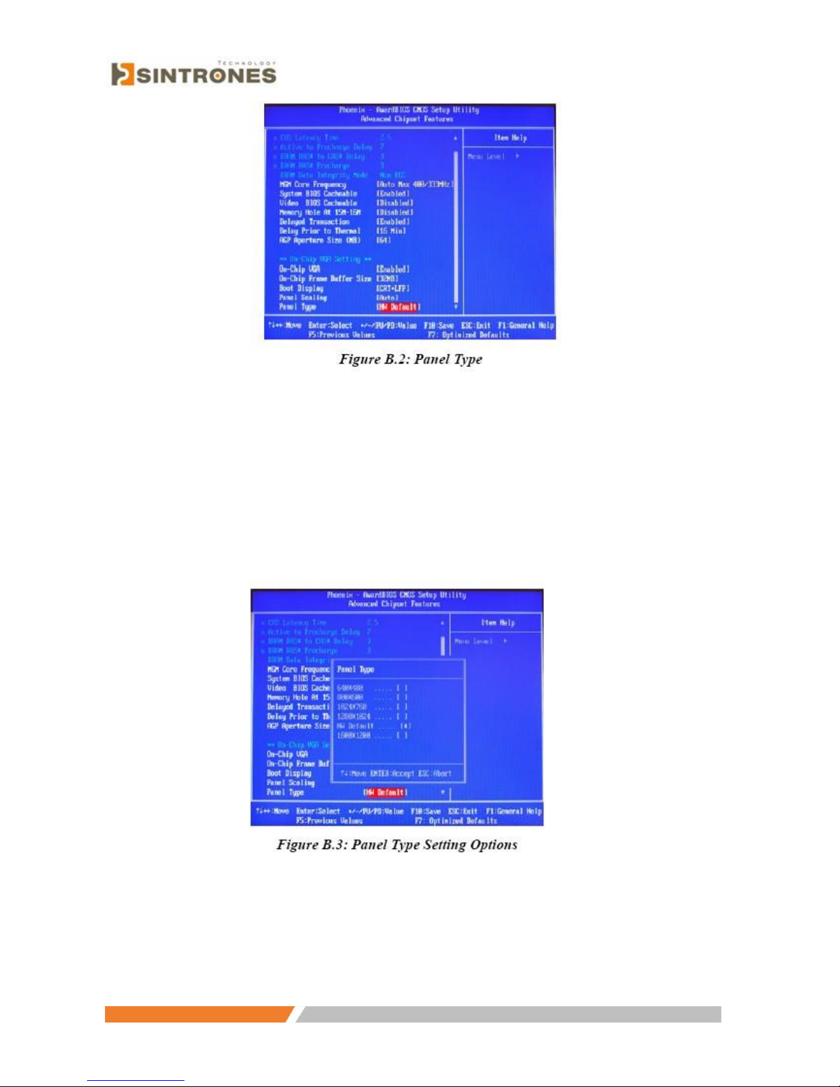
2. Choose .Panel Type;. the default is to set on .HW Default. and the panel
setting is determined by jumper. (Refer to 4.3.2)
Page 58
www.sintroncorp.com
Address: 2880 Zanker Rd, Suite 207, San Jose CA 95134 USA TEL: 408-800-1413 / FAX: 510-952-8282 / [email protected]
3. The Panel Type Setting in BIOS has 6 options available. Besides .HW
Default. you can choose the setting that corresponds to the specifications of
your panel. Selecting a specific value overrides the automatic HW Default
setting. Options are: 640 x 480, 800 x 600, 1024 x 768, 1280 x 1024, HW
Default, 1600 x 1200.
Page 59
www.sintroncorp.com
Address: 2880 Zanker Rd, Suite 207, San Jose CA 95134 USA TEL: 408-800-1413 / FAX: 510-952-8282 / [email protected]
B.2 Power Fail Function Setting in BIOS
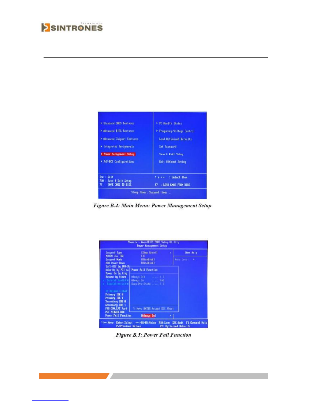
To set the .power fail. function in BIOS and to activate the .power on function via
ignition switch,. follow these instructions:
1. Choose“Power Management Setup”. in the main menu of BIOS.
2. Choose“Power Fail Function”. and then select“Always On”.
3. To disable the Power-On function by using the ignition switch, select .Always
Off,. so the Power-On/Off function can be controlled by the power button.
 Loading...